EP1031293B1 - Schuh- oder Einlegesohle und deren Herstellungsverfahren - Google Patents
Schuh- oder Einlegesohle und deren Herstellungsverfahren Download PDFInfo
- Publication number
- EP1031293B1 EP1031293B1 EP99309664A EP99309664A EP1031293B1 EP 1031293 B1 EP1031293 B1 EP 1031293B1 EP 99309664 A EP99309664 A EP 99309664A EP 99309664 A EP99309664 A EP 99309664A EP 1031293 B1 EP1031293 B1 EP 1031293B1
- Authority
- EP
- European Patent Office
- Prior art keywords
- bottom plate
- sole
- insole
- foot
- shoe
- Prior art date
- Legal status (The legal status is an assumption and is not a legal conclusion. Google has not performed a legal analysis and makes no representation as to the accuracy of the status listed.)
- Expired - Lifetime
Links
- 238000004519 manufacturing process Methods 0.000 title description 2
- 210000002683 foot Anatomy 0.000 claims abstract description 40
- 239000012530 fluid Substances 0.000 claims abstract description 39
- 230000002093 peripheral effect Effects 0.000 claims abstract description 32
- 210000003371 toe Anatomy 0.000 claims abstract description 15
- 210000001872 metatarsal bone Anatomy 0.000 claims abstract description 7
- XLYOFNOQVPJJNP-UHFFFAOYSA-N water Substances O XLYOFNOQVPJJNP-UHFFFAOYSA-N 0.000 claims abstract description 3
- 230000008020 evaporation Effects 0.000 claims description 6
- 238000001704 evaporation Methods 0.000 claims description 6
- 210000000454 fifth toe Anatomy 0.000 claims description 6
- 210000000453 second toe Anatomy 0.000 claims description 5
- 239000007798 antifreeze agent Substances 0.000 claims description 4
- 229920005992 thermoplastic resin Polymers 0.000 claims description 4
- 241000894006 Bacteria Species 0.000 claims description 3
- 230000035699 permeability Effects 0.000 claims description 3
- 210000001255 hallux Anatomy 0.000 claims description 2
- 239000000463 material Substances 0.000 claims description 2
- 230000035939 shock Effects 0.000 abstract description 7
- 238000003466 welding Methods 0.000 abstract description 7
- 239000004576 sand Substances 0.000 description 4
- DNIAPMSPPWPWGF-UHFFFAOYSA-N Propylene glycol Chemical compound CC(O)CO DNIAPMSPPWPWGF-UHFFFAOYSA-N 0.000 description 3
- 230000033001 locomotion Effects 0.000 description 3
- 210000004243 sweat Anatomy 0.000 description 3
- 238000009792 diffusion process Methods 0.000 description 2
- 239000000428 dust Substances 0.000 description 2
- 230000000694 effects Effects 0.000 description 2
- 239000002184 metal Substances 0.000 description 2
- 238000000465 moulding Methods 0.000 description 2
- 206010016322 Feeling abnormal Diseases 0.000 description 1
- 238000010521 absorption reaction Methods 0.000 description 1
- 239000000853 adhesive Substances 0.000 description 1
- 230000001070 adhesive effect Effects 0.000 description 1
- 238000005520 cutting process Methods 0.000 description 1
- 238000001746 injection moulding Methods 0.000 description 1
- 230000009545 invasion Effects 0.000 description 1
- 230000008018 melting Effects 0.000 description 1
- 238000002844 melting Methods 0.000 description 1
- 230000035790 physiological processes and functions Effects 0.000 description 1
- 238000003825 pressing Methods 0.000 description 1
- 230000001737 promoting effect Effects 0.000 description 1
- 239000000243 solution Substances 0.000 description 1
- 229920003002 synthetic resin Polymers 0.000 description 1
- 239000000057 synthetic resin Substances 0.000 description 1
- 229920001169 thermoplastic Polymers 0.000 description 1
- 239000004416 thermosoftening plastic Substances 0.000 description 1
- 210000001835 viscera Anatomy 0.000 description 1
Images



Classifications
-
- A—HUMAN NECESSITIES
- A43—FOOTWEAR
- A43B—CHARACTERISTIC FEATURES OF FOOTWEAR; PARTS OF FOOTWEAR
- A43B7/00—Footwear with health or hygienic arrangements
- A43B7/14—Footwear with health or hygienic arrangements with foot-supporting parts
- A43B7/1405—Footwear with health or hygienic arrangements with foot-supporting parts with pads or holes on one or more locations, or having an anatomical or curved form
- A43B7/1415—Footwear with health or hygienic arrangements with foot-supporting parts with pads or holes on one or more locations, or having an anatomical or curved form characterised by the location under the foot
- A43B7/144—Footwear with health or hygienic arrangements with foot-supporting parts with pads or holes on one or more locations, or having an anatomical or curved form characterised by the location under the foot situated under the heel, i.e. the calcaneus bone
-
- A—HUMAN NECESSITIES
- A43—FOOTWEAR
- A43B—CHARACTERISTIC FEATURES OF FOOTWEAR; PARTS OF FOOTWEAR
- A43B17/00—Insoles for insertion, e.g. footbeds or inlays, for attachment to the shoe after the upper has been joined
- A43B17/02—Insoles for insertion, e.g. footbeds or inlays, for attachment to the shoe after the upper has been joined wedge-like or resilient
- A43B17/026—Insoles for insertion, e.g. footbeds or inlays, for attachment to the shoe after the upper has been joined wedge-like or resilient filled with a non-compressible fluid, e.g. gel, water
-
- A—HUMAN NECESSITIES
- A43—FOOTWEAR
- A43B—CHARACTERISTIC FEATURES OF FOOTWEAR; PARTS OF FOOTWEAR
- A43B7/00—Footwear with health or hygienic arrangements
- A43B7/14—Footwear with health or hygienic arrangements with foot-supporting parts
- A43B7/1405—Footwear with health or hygienic arrangements with foot-supporting parts with pads or holes on one or more locations, or having an anatomical or curved form
- A43B7/1415—Footwear with health or hygienic arrangements with foot-supporting parts with pads or holes on one or more locations, or having an anatomical or curved form characterised by the location under the foot
- A43B7/1445—Footwear with health or hygienic arrangements with foot-supporting parts with pads or holes on one or more locations, or having an anatomical or curved form characterised by the location under the foot situated under the midfoot, i.e. the second, third or fourth metatarsal
-
- A—HUMAN NECESSITIES
- A43—FOOTWEAR
- A43B—CHARACTERISTIC FEATURES OF FOOTWEAR; PARTS OF FOOTWEAR
- A43B7/00—Footwear with health or hygienic arrangements
- A43B7/14—Footwear with health or hygienic arrangements with foot-supporting parts
- A43B7/1405—Footwear with health or hygienic arrangements with foot-supporting parts with pads or holes on one or more locations, or having an anatomical or curved form
- A43B7/1455—Footwear with health or hygienic arrangements with foot-supporting parts with pads or holes on one or more locations, or having an anatomical or curved form with special properties
- A43B7/146—Footwear with health or hygienic arrangements with foot-supporting parts with pads or holes on one or more locations, or having an anatomical or curved form with special properties provided with acupressure points or means for foot massage
Definitions
- the present invention relates to an insole or sole for a shoe which seeks an effect of shock absorption during walking and also a massage effect owing to excitement of the sole of the foot while providing for a stable and comfortable sense of wear.
- the applicant has earlier proposed a sole or insole for a shoe, which absorbs shock during walking while massaging the sole of the foot by excitement thereof.
- the proposed sole or insole for a shoe comprises a bottom plate, a plurality of blades formed integrally thereon, a cover with an outer periphery thereof bonded to an outer periphery of the bottom plate and fluid sealed in between the bottom plate and the cover.
- a recess portion having a shape corresponding to the sole of a foot is formed in an upper surface of the bottom plate.
- the blades are integrally formed on a bottom surface of the recess portion of the bottom plate. The blades are slanted and extend in directions perpendicular to a longitudinal direction of the bottom plate.
- the cover is formed with a recess portion having a shape corresponding to the sole of a foot and an outer peripheral portion having a predetermined width surrounding the recess portion.
- the outer peripheral portion of the cover is welded to the outer peripheral portion of the bottom plate (cf. Japanese Patent No. 2549602, US Patent 5189816 or US Patent No. 5365678).
- the applicant has also proposed another sole or insole for a shoe, in which grooves are formed in a middle portion of each of a plurality of blades so that fluid can be moved through these grooves. Outer end portions of a plurality of blades are connected to an inner end of a bottom plate through respective webs, each of which is lower than the blade to allow the fluid to pass therethrough (cf. Japanese Patent No. 1959712).
- the conventional insole or sole for a shoe massages the sole of a foot by excitement thereof during walking.
- a heel portion of the sole of the foot is landed, first, and, then, a tarsal portion of the sole, which includes an area of the sole from the heel to a substantial center portion of the sole, is landed.
- a metatarsal portion of the sole which includes an area from the tarsal sole portion to the roots of the toes, is landed and, finally, the toes kick the land.
- the recess portions of both the bottom plate and the cover of the conventional insole or sole of shoes which are necessary for absorbing shock and massaging the sole of foot during walking, correspond in shape and size to the whole sole of a foot including the toes and a space defined by these recess portions is filled with the fluid. Therefore, the kicking force of the toes during walking is absorbed by the fluid, causing the walking to be difficult. This difficulty may be similar to a case of walking on sand.
- the whole area of the bottom plate and the whole area of the cover, except their recess portions, are completely welded to each other by means of a high frequency welder and the whole welded area includes a relatively wide portion in front of the toes of the foot and narrow portions on both sides of the recess portions. Therefore, if a high frequency of high power is used in order to obtain a predetermined welding strength in the relatively wide portion, the welding strength of the whole welded area becomes non-uniform, causing the whole insole or sole to be distorted and/or causing the fluid to leak.
- the conventional blades are rectangular, have grooves in the middle portions thereof and have the opposite end portions connected to an inner wall of the edge portions of the bottom plate through the webs. Therefore, in order to mold such blades, a metal mold having complicated configuration is required and the molding work itself is complicated. Further, in order to make the flow of fluid smooth, it is necessary to widen the space through which the fluid flows, by making the blades higher than the webs by a predetermined amount. Therefore, the blades become so high that the thickness of the bottom plate has to be increased. This limits the wearing comfort of shoes and the freedom of design thereof.
- An object of the present invention is to provide an insole or sole for a shoe, which absorbs shock during walking and massages the sole of the foot owing to excitement of the sole of the foot, while giving a stable and conformable sense of wear, has a plurality of easily formable blades and can prevent fluid from leaking by making a welding of a bottom plate and a cover reliable.
- Another object of the present invention is to provide an insole or sole for a shoe, which has a bottom plate formed with a recess corresponding in configuration to a combination of the tarsal and metatarsal portions of the foot, provides a stable and comfortable sense of walking unlike the unstable feeling of walking on sand and does not provide any pain even when a wearer walks for a long time since the effective point existing in roots of the toes is not excited at all or is substantially not excited.
- Another object of the present invention is to provide an insole or sole for a shoe, which has a plurality of blades formed on a bottom surface of a recess of a bottom plate and each having an arc ridge so that spaces are provided between opposite end portions of the arc blades and an inner wall of the recess portion of the bottom plate.
- a further object of the present invention is to provide an insole or sole for a shoe, which has a plurality of arc shaped blades formed on a bottom surface of a recess portion of a bottom plate, end portions of the blades located in an area corresponding to an area between a little toe and a second toe or located in an area corresponding to an area between the little toe and a big toe being swollen so that a leakage of fluid by pressure can be prevented more reliably.
- Another object of the present invention is to provide an insole or sole for a shoe, in which a bottom plate having a recess portion and a cover having a recess portion are joined together by welding peripheral portions of the bottom plate and the cover, which directly surround the respective recess portions and have a uniform width, together so that, even if a high power, high frequency is used in order to obtain a predetermined welding strength, there is no twisting phenomenon of the whole insole or sole of shoes and the leakage of fluid can be prevented more reliably.
- Another object of the present invention is to provide an insole or sole for a shoe, in which a non-welded portion of the bottom plate and the cover is spot-welded in order to prevent sand or dust from entering in between the non-welded bottom plate and the non-welded cover, in which an uneven pattern is formed in an upper surface of the cover in order to promote diffusion and evaporation of sweat and/or in which a sheet is attached to a lower surface of the bottom plate in order to reduce discomfort when fluid leaks during walking.
- the present invention resides in an insole or sole for a shoe, comprising:
- the size of the recess portion may be the same as that of the tarsal portion and the metatarsal portion of foot or smaller analogously. It is preferable that a front-end portion of the recess portion does not reach roots of toes.
- Each of the blades may have an arc ridge form with opposite end portions being sloped gently down and spaces may be provided between the opposite end portions of the blades and an inner wall of the recess portion of the bottom plate. It is preferable that one end portion of some of the blades, which are located in an area corresponding to an area between a little toe and a second toe of a foot may be swollen compared with the other end portions in order to reduce fluid pressure at those end portions of the blades.
- the bottom plate having the recess portion and the cover having the recess portion may be joined together by welding together along a peripheral line having a uniform width, the peripheral portions directly surrounding the respective recesses, a remaining portion surrounding the welded portion being left unwelded. It is preferable that the remaining portion which is not welded along said peripheral line is spot-welded at a plurality of points. Further, it is preferable to form an uneven pattern on the cover. Further, it is preferable to attach the sheet to the lower surface of the bottom plate.
- the fluid may have low permeability and low evaporation and may be resistant to bacteria. An antifreeze agent may be added to the fluid.
- An insole or sole of a shoe according to the present invention is constructed with a bottom plate 1, a plurality of blades 11 (111 ⁇ 114) integrally formed in the bottom plate, a cover 2 bonded to the bottom plate and fluid injected in between the bottom plate and the cover.
- the bottom plate 1 is integrally formed by an injection molding of thermoplastic resin.
- a recess portion 12 is formed in an upper surface of the bottom plate 1, leaving a thick outer peripheral portion 13.
- the recess portion 12 corresponds, in shape and size, to a combination of a tarsal portion of the foot covering a heel to substantially a center portion of the foot and a metatarsal portion covering an area from the tarsal portion to the roots of the toes. It should be noted that the recess portion 12 may be analogously smaller in size than the shown recess portion.
- a front-end portion of the recess portion 12 may reach the roots of the toes, it is preferable that the front-end portion of the recess portion 12 does not reach the roots of the toes.
- a plurality of blades 11 111,112,113,114 are integrally formed on a bottom plate of the recess portion 12. The blades 11 extend in directions perpendicular to a longitudinal direction of the bottom plate 1 and are slanted toward the heel as shown in Fig. 2.
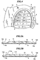
- Each blade 11 takes in the form of a thin arc ridge having a smooth ridgeline as shown in Fig. 5A. Since the opposite end portions of the ridge are separated from a concaved inner wall 12a of the recess portion 12 and the opposite end portions of the blades 11 do not reach the concaved inner wall 12a of the recess portion 12 as shown in Fig. 5A, large spaces V are provided between the end portions of the blades 11 and the inner wall 12a of the recess 12 so that the movement of fluid is facilitated through the spaces V.
- FIG. 11 those formed in a front-end portion of the recess 12 are depicted by reference numerals 111, 112, 113 and 114.
- the blades 111, 112, 113, and 114 have left side end portions 111a, 112a, 113a and 114a corresponding in position to the area between the little toes and the second toe as shown in Fig. 4.
- the left side end portions 111a, 112a, 113a and 114a are swollen compared with those of the other blades to form thick and sharp edge portions having a large curvature, compared with those of the blades 11, as shown in Fig. 5B.
- the space v between the inner wall 12a of the recess portion 12 and the left side end portion of the blade 113 is smaller than the space V provided by the blade 11, so that the fluid pressure caused by an external pressing force is reduced by the left side end portions 111a to 114a to thereby reduce the movement of fluid.
- the inner wall 12a of the recess portion 12 of the bottom plate 1 has a concave configuration having a thicker portion 13a so that the thickness of the bottom plate 1 becomes continuously larger toward the outer peripheral portion 13 of the bottom plate 1.
- An area of a front half of the outer peripheral portion 13 of the recess portion 12 of the bottom plate 1 is made larger than that of the opposite side portions of the outer peripheral portion 13, in order to regulate the size and/or shape of the outer peripheral portion concomitantly with the size and/or shape of the shoe, to which the insole or sole of the present invention is applied, by partially cutting away the front half portion of the outer peripheral portion 13 of the bottom plate 1 suitably.
- the blades 11 protrude from the surface of the outer peripheral portion 13 of the bottom plate 1. Therefore, in an assembled state of the insole or sole for a shoe, the blades 11 are resiliently bent by a recess portion 21 of the cover 2, so that the blades 11 can excite the sole of foot through the cover 2 to thereby massage the sole of foot.
- the cover 2 is formed of thermoplastic synthetic resin similar to the thermoplastic resin used to form the bottom plate 1.
- the cover 2 has an outer peripheral portion 22 surrounding the recess portion 21.
- the configurations of the recess portion 21 and the outer peripheral portion 22 are the same as the configurations of the recess portion 12 and the outer peripheral portion 13 of the bottom plate 1, respectively, and the thickness of the outer peripheral portion 22 of the cover 2 is the same as that of the outer peripheral portion 13 of the bottom plate 1.
- a thicker portion 22a is formed in an inner wall 21a of the recess portion 21 of the cover 2 so that the thickness of the cover 2 becomes continuously larger toward the outer peripheral portion 22.
- an uneven pattern for example, a concave or aventurine pattern is formed on the surface of the cover 2 in order to prevent sweat droplets from staying on the upper surface of the cover while promoting diffusion and evaporation of sweat.
- the outer peripheral portions 13 and 22 of the bottom plate 1 and the cover 2 which have the same thickness, are mated and welded together by high frequency welder, welded portions 3 and 4 having uniform widths and provided in inner peripheral portions of the outer peripheral portions 12 and 22.
- the portions of the outer peripheral portions 12 and 22 outside the weld portions are left non-welded. Since the widths of the weld portions 3 and 4 are uniform throughout thereof, the adhesive strength is uniform, so that it is possible to maintain the whole insole or sole for a shoe flat and to prevent fluid leakage. Further, the non-welded portions of the bottom plate and the cover are spot-welded at three points 5 as shown in Fig. 1. Therefore, invasion of sand or dust to the adhering surfaces, which are not completely welded, can be prevented.
- the fluid such as water
- the fluid may be a solution, which has low permeability, has a low evaporation, has high flowability and resistant to bacteria.
- the fluid may be frozen and the so-called puncture may occur, it is preferable to mix an antifreeze agent in the fluid.
- propylene glycol is mixed in the fluid as the antifreeze agent, it is possible to prevent a reduction of shock absorbing performance due to natural evaporation of the fluid.
- the curvature of the outside end portions 111a, 112a, 113a and 114a of the blades 111, 112, 113 and 114, which correspond to the area between the little toe and the second toe is made larger.
- the curvature of the other end portions of the blades 111 to 114, which are represented by the other end portion 113b of the blade 113 may be made larger, too, in order to reduce the fluid pressure on the both end portions.
Landscapes
- Health & Medical Sciences (AREA)
- Epidemiology (AREA)
- General Health & Medical Sciences (AREA)
- Public Health (AREA)
- Footwear And Its Accessory, Manufacturing Method And Apparatuses (AREA)
Claims (11)
- Einlegesohle oder Sohle für einen Schuh, umfassend:dadurch gekennzeichnet, dass der genannte Ausnehmungsteil eine Konfiguration aufweist, die einer Kombination aus einem Fußwurzelknochenteil eines Fußes, der einen Bereich von einer Hacke bis im wesentlichen zu einem Mittelteil des Fußes bedeckt, und einem Mittelfußknochenteil des Fußes entspricht, der einen Bereich von dem Mittelteil bis zu den Zehwurzeln des Fußes bedeckt.eine Bodenplatte (1) gebildet aus einem thermoplastischen Harzmaterial, wobei die genannte Bodenplatte mit einem Ausnehmungsteil (12) in einer oberen Oberfläche derselben ausgebildet ist;eine Mehrzahl von Flügeln (11), die integriert auf einer Bodenfläche des genannten Ausnehmungsteils (12) der genannten Bodenplatte (1) ausgebildet sind, wobei die Mehrzahl der genannten Flügel sich in Richtungen rechtwinklig zu einer Längsrichtung der genannten Bodenplatte erstrecken und in Richtung auf einen Hackenteil der genannten Bodenplatte abgeschrägt sind;eine Abdeckung (2), die an einen Umfangsteil (13) der genannten Bodenplatte geklebt ist, wobei der genannte Umfangsteil den genannten Ausnehmungsteil (12) umschließt; undFluid, das in einem durch den genannten Ausnehmungsteil der genannten Bodenplatte (1) und der genannten Abdeckung (2) begrenzten Raum versiegelt ist;
- Einlegesohle oder Sohle für einen Schuh nach Anspruch 1, bei der jeder der genannten Flügel (11) einen Bogensteg aufweist, und
Räume (V, v) zwischen einer Innenwand (12a) des genannten Ausnehmungsteils der genannten Bodenplatte und gegenüberliegenden Endteilen der genannten Flügel vorgesehen sind. - Schuheinlegesohle oder -Sohle nach Anspruch 1 oder Anspruch 2, bei der zum Senken des Fluiddrucks Endteile (111a) der genannten Flügel (11), die in einem Bereich des genannten Ausnehmungsteils positioniert sind, der einem Bereich des Fußes zwischen einem kleinen Zeh und einem zweiten Zeh des Fußes entspricht, verglichen mit den anderen Endteilen der genannten Flügel aufgequollen oder vergrößert werden.
- Schuheinlegesohle oder -Sohle nach einem der Ansprüche 1 bis 3, bei der zum Senken des Fluiddrucks gegenüberliegende Endteile der genannten Flügel (11), die in einem Bereich des genannten Ausnehmungsteils (12) positioniert sind, der einem Bereich des Fußes zwischen einem kleinen Zeh und einem großen Zeh entspricht, verglichen mit den anderen Endteilen der genannten Flügel aufgequollen oder vergrößert werden.
- Einlegesohle oder Sohle für einen Schuh nach einem der Ansprüche 1 bis 4, bei der die genannte Abdeckung an die genannte Bodenplatte entlang einer Umfanglinie geschweißt wird, die eine einheitliche Breite hat und direkt den genannten Ausnehmungsteil (12) der genannten Bodenplatte umschließt, und ein verbleibender Teil des genannten Umfangsteils der genannten Bodenplatte ungeschweißt belassen wird.
- Schuheinlegesohle oder -Sohle nach Anspruch 5, bei der der genannte verbleibende Teil, der nicht entlang der genannten Umfangslinie geschweißt wird, punktgeschweißt wird.
- Schuheinlegesohle oder -Sohle nach einem der vorhergehenden Ansprüche, bei der ein ungleichmäßiges Muster auf einer oberen Oberfläche der genannten Abdeckung (2) ausgebildet ist.
- Schuheinlegesohle oder -Sohle nach einem der vorhergehenden Ansprüche, die ferner eine Platte aufweist, welche an eine untere Oberfläche der genannten Bodenplatte geklebt ist.
- Schuheinlegesohle oder -Sohle nach einem der vorhergehenden Ansprüche, bei der das genannte Fluid niedrige Wasserpermeabilität aufweist und niedrige Verdampfung aufweist.
- Schuheinlegesohle oder -Sohle nach einem der vorhergehenden Ansprüche, bei der das genannte Fluid bakterienresistent ist.
- Schuheinlegesohle oder -Sohle nach einem der vorhergehenden Ansprüche, bei der ein Frostschutzmittel in das genannte Fluid gemischt ist.
Applications Claiming Priority (2)
| Application Number | Priority Date | Filing Date | Title |
|---|---|---|---|
| JP11044730A JP2000236908A (ja) | 1999-02-23 | 1999-02-23 | 靴の中底または靴底 |
| JP4473099 | 1999-02-23 |
Publications (2)
| Publication Number | Publication Date |
|---|---|
| EP1031293A1 EP1031293A1 (de) | 2000-08-30 |
| EP1031293B1 true EP1031293B1 (de) | 2004-06-02 |
Family
ID=12699572
Family Applications (1)
| Application Number | Title | Priority Date | Filing Date |
|---|---|---|---|
| EP99309664A Expired - Lifetime EP1031293B1 (de) | 1999-02-23 | 1999-12-01 | Schuh- oder Einlegesohle und deren Herstellungsverfahren |
Country Status (7)
| Country | Link |
|---|---|
| US (1) | US6367174B1 (de) |
| EP (1) | EP1031293B1 (de) |
| JP (1) | JP2000236908A (de) |
| AT (1) | ATE268129T1 (de) |
| DE (1) | DE69917741T2 (de) |
| ES (1) | ES2221321T3 (de) |
| TW (1) | TW411257B (de) |
Families Citing this family (11)
| Publication number | Priority date | Publication date | Assignee | Title |
|---|---|---|---|---|
| US20030150134A1 (en) * | 2002-02-11 | 2003-08-14 | Hardt John C | Anti-roll arch support insole |
| US7622014B2 (en) * | 2005-07-01 | 2009-11-24 | Reebok International Ltd. | Method for manufacturing inflatable footwear or bladders for use in inflatable articles |
| WO2008102391A1 (en) * | 2007-02-23 | 2008-08-28 | Scm Consulting S.A.S. | Inner sole |
| CN102131417B (zh) * | 2008-08-27 | 2012-07-04 | 株式会社卑弥呼 | 鞋底夹层及鞋子 |
| US8991072B2 (en) * | 2010-02-22 | 2015-03-31 | Nike, Inc. | Fluid-filled chamber incorporating a flexible plate |
| US8769846B1 (en) * | 2011-04-26 | 2014-07-08 | Vernon Williams | Boot having skin-exfoliating means therein |
| US9603414B2 (en) | 2013-03-15 | 2017-03-28 | Nike, Inc. | Fluid-filled chamber with a tensile element |
| MX2014006573A (es) * | 2013-05-22 | 2015-06-10 | Himiko Co Ltd | Elementos de suela de calzado. |
| US10888137B2 (en) * | 2017-03-17 | 2021-01-12 | Desarrollo Integral Del Molde, S.L. | Footwear sole |
| US11547179B2 (en) * | 2018-10-16 | 2023-01-10 | Adam Urbain | Tactile feedback shoe sole |
| PL3741245T3 (pl) * | 2019-05-23 | 2024-12-23 | Ltwhp, Llc | Podeszwa do obuwia sportowego, obuwia roboczego lub obuwia do rekreacji |
Family Cites Families (7)
| Publication number | Priority date | Publication date | Assignee | Title |
|---|---|---|---|---|
| US2549602A (en) | 1949-10-01 | 1951-04-17 | Indiana Steel Products Co | Applicator for ion traps |
| FR2591441B1 (fr) | 1985-12-13 | 1988-03-18 | Mauger Jean | Semelle ou premiere de chaussure avec circulation d'un fluide incorpore |
| US4744157A (en) * | 1986-10-03 | 1988-05-17 | Dubner Benjamin B | Custom molding of footgear |
| US5189816A (en) * | 1990-11-22 | 1993-03-02 | Kabushiki Kaisha Himiko | Mid-sole or sole of shoes |
| JP2549602B2 (ja) * | 1992-05-07 | 1996-10-30 | 株式会社卑弥呼 | 靴の中底または靴底 |
| ATE220299T1 (de) | 1993-04-15 | 2002-07-15 | Henning Raun Schoesler | Flüssigkeitsgefüllte einlegesohle |
| WO1997025551A2 (en) | 1996-01-05 | 1997-07-17 | William Alexander Courtney | Device incorporating elastic fluids and viscous damping |
-
1999
- 1999-02-23 JP JP11044730A patent/JP2000236908A/ja active Pending
- 1999-07-13 US US09/351,651 patent/US6367174B1/en not_active Expired - Lifetime
- 1999-07-20 TW TW088112492A patent/TW411257B/zh not_active IP Right Cessation
- 1999-12-01 EP EP99309664A patent/EP1031293B1/de not_active Expired - Lifetime
- 1999-12-01 AT AT99309664T patent/ATE268129T1/de not_active IP Right Cessation
- 1999-12-01 ES ES99309664T patent/ES2221321T3/es not_active Expired - Lifetime
- 1999-12-01 DE DE69917741T patent/DE69917741T2/de not_active Expired - Lifetime
Also Published As
| Publication number | Publication date |
|---|---|
| ES2221321T3 (es) | 2004-12-16 |
| DE69917741T2 (de) | 2005-05-25 |
| EP1031293A1 (de) | 2000-08-30 |
| DE69917741D1 (de) | 2004-07-08 |
| HK1032180A1 (en) | 2001-07-13 |
| US6367174B1 (en) | 2002-04-09 |
| TW411257B (en) | 2000-11-11 |
| ATE268129T1 (de) | 2004-06-15 |
| JP2000236908A (ja) | 2000-09-05 |
Similar Documents
| Publication | Publication Date | Title |
|---|---|---|
| EP0571103B1 (de) | Mittensohle oder Sohle für Schuhe | |
| US11432616B2 (en) | Method of customizing a sole structure of an article of footwear | |
| JP5102256B2 (ja) | 伸縮可能なアッパーと分節された履物底構造とを有する履物 | |
| CN102131417B (zh) | 鞋底夹层及鞋子 | |
| JP2635538B2 (ja) | 靴用外底 | |
| JP3135954B2 (ja) | 靴 底 | |
| US6367174B1 (en) | Insole or sole of shoes and manufacturing method thereof | |
| MXPA98000432A (en) | Planti | |
| KR19990028483A (ko) | 신발 안창 | |
| WO2009136685A1 (en) | A shoe inner soles | |
| EP3267822A1 (de) | Auxetische strukturen und schuh mit sohlen mit auxetischen strukturen | |
| WO2007132567A1 (ja) | 靴底用中敷 | |
| JPH042041B2 (de) | ||
| HK1032180B (en) | Insole or sole of shoes and manufacturing method thereof | |
| WO2014188546A1 (ja) | 履物の底部材 | |
| JP3615532B2 (ja) | 靴の中底又は靴底 | |
| KR200205881Y1 (ko) | 신발용 코르크중창 | |
| CA2095272C (en) | Mid-sole or sole of shoes | |
| JP2566628Y2 (ja) | 靴の靴底 | |
| KR200285187Y1 (ko) | 일회용 신발 깔창 | |
| JPH0662909A (ja) | 靴の中底または靴底 | |
| HK1155621B (en) | Shoe inner sole and footwear | |
| KR19990031104A (ko) | 신발 | |
| KR20020084673A (ko) | 파형 신발창 |
Legal Events
| Date | Code | Title | Description |
|---|---|---|---|
| PUAI | Public reference made under article 153(3) epc to a published international application that has entered the european phase |
Free format text: ORIGINAL CODE: 0009012 |
|
| AK | Designated contracting states |
Kind code of ref document: A1 Designated state(s): AT BE CH CY DE DK ES FI FR GB GR IE IT LI LU MC NL PT SE |
|
| AX | Request for extension of the european patent |
Free format text: AL;LT;LV;MK;RO;SI |
|
| 17P | Request for examination filed |
Effective date: 20010222 |
|
| AKX | Designation fees paid |
Free format text: AT BE CH CY DE DK ES FI FR GB GR IE IT LI LU MC NL PT SE |
|
| 17Q | First examination report despatched |
Effective date: 20030304 |
|
| GRAP | Despatch of communication of intention to grant a patent |
Free format text: ORIGINAL CODE: EPIDOSNIGR1 |
|
| GRAS | Grant fee paid |
Free format text: ORIGINAL CODE: EPIDOSNIGR3 |
|
| GRAA | (expected) grant |
Free format text: ORIGINAL CODE: 0009210 |
|
| RAP1 | Party data changed (applicant data changed or rights of an application transferred) |
Owner name: KABUSHIKI KAISHA HIMIKO |
|
| AK | Designated contracting states |
Kind code of ref document: B1 Designated state(s): AT BE CH CY DE DK ES FI FR GB GR IE IT LI LU MC NL PT SE |
|
| PG25 | Lapsed in a contracting state [announced via postgrant information from national office to epo] |
Ref country code: FI Free format text: LAPSE BECAUSE OF FAILURE TO SUBMIT A TRANSLATION OF THE DESCRIPTION OR TO PAY THE FEE WITHIN THE PRESCRIBED TIME-LIMIT Effective date: 20040602 Ref country code: CY Free format text: LAPSE BECAUSE OF FAILURE TO SUBMIT A TRANSLATION OF THE DESCRIPTION OR TO PAY THE FEE WITHIN THE PRESCRIBED TIME-LIMIT Effective date: 20040602 Ref country code: BE Free format text: LAPSE BECAUSE OF FAILURE TO SUBMIT A TRANSLATION OF THE DESCRIPTION OR TO PAY THE FEE WITHIN THE PRESCRIBED TIME-LIMIT Effective date: 20040602 Ref country code: AT Free format text: LAPSE BECAUSE OF FAILURE TO SUBMIT A TRANSLATION OF THE DESCRIPTION OR TO PAY THE FEE WITHIN THE PRESCRIBED TIME-LIMIT Effective date: 20040602 |
|
| REG | Reference to a national code |
Ref country code: GB Ref legal event code: FG4D |
|
| REG | Reference to a national code |
Ref country code: CH Ref legal event code: EP |
|
| REF | Corresponds to: |
Ref document number: 69917741 Country of ref document: DE Date of ref document: 20040708 Kind code of ref document: P |
|
| REG | Reference to a national code |
Ref country code: CH Ref legal event code: NV Representative=s name: ISLER & PEDRAZZINI AG |
|
| REG | Reference to a national code |
Ref country code: IE Ref legal event code: FG4D |
|
| PG25 | Lapsed in a contracting state [announced via postgrant information from national office to epo] |
Ref country code: SE Free format text: LAPSE BECAUSE OF FAILURE TO SUBMIT A TRANSLATION OF THE DESCRIPTION OR TO PAY THE FEE WITHIN THE PRESCRIBED TIME-LIMIT Effective date: 20040902 Ref country code: GR Free format text: LAPSE BECAUSE OF FAILURE TO SUBMIT A TRANSLATION OF THE DESCRIPTION OR TO PAY THE FEE WITHIN THE PRESCRIBED TIME-LIMIT Effective date: 20040902 Ref country code: DK Free format text: LAPSE BECAUSE OF FAILURE TO SUBMIT A TRANSLATION OF THE DESCRIPTION OR TO PAY THE FEE WITHIN THE PRESCRIBED TIME-LIMIT Effective date: 20040902 |
|
| REG | Reference to a national code |
Ref country code: HK Ref legal event code: GR Ref document number: 1032180 Country of ref document: HK |
|
| PG25 | Lapsed in a contracting state [announced via postgrant information from national office to epo] |
Ref country code: LU Free format text: LAPSE BECAUSE OF NON-PAYMENT OF DUE FEES Effective date: 20041201 Ref country code: IE Free format text: LAPSE BECAUSE OF NON-PAYMENT OF DUE FEES Effective date: 20041201 |
|
| REG | Reference to a national code |
Ref country code: ES Ref legal event code: FG2A Ref document number: 2221321 Country of ref document: ES Kind code of ref document: T3 |
|
| PG25 | Lapsed in a contracting state [announced via postgrant information from national office to epo] |
Ref country code: MC Free format text: LAPSE BECAUSE OF NON-PAYMENT OF DUE FEES Effective date: 20041231 |
|
| ET | Fr: translation filed | ||
| PLBE | No opposition filed within time limit |
Free format text: ORIGINAL CODE: 0009261 |
|
| STAA | Information on the status of an ep patent application or granted ep patent |
Free format text: STATUS: NO OPPOSITION FILED WITHIN TIME LIMIT |
|
| 26N | No opposition filed |
Effective date: 20050303 |
|
| REG | Reference to a national code |
Ref country code: IE Ref legal event code: MM4A |
|
| REG | Reference to a national code |
Ref country code: CH Ref legal event code: PCAR Free format text: ISLER & PEDRAZZINI AG;POSTFACH 1772;8027 ZUERICH (CH) |
|
| PG25 | Lapsed in a contracting state [announced via postgrant information from national office to epo] |
Ref country code: PT Free format text: LAPSE BECAUSE OF NON-PAYMENT OF DUE FEES Effective date: 20041102 |
|
| PGFP | Annual fee paid to national office [announced via postgrant information from national office to epo] |
Ref country code: NL Payment date: 20111220 Year of fee payment: 13 Ref country code: CH Payment date: 20111213 Year of fee payment: 13 |
|
| PGFP | Annual fee paid to national office [announced via postgrant information from national office to epo] |
Ref country code: ES Payment date: 20120116 Year of fee payment: 13 |
|
| REG | Reference to a national code |
Ref country code: NL Ref legal event code: V1 Effective date: 20130701 |
|
| REG | Reference to a national code |
Ref country code: CH Ref legal event code: PL |
|
| PG25 | Lapsed in a contracting state [announced via postgrant information from national office to epo] |
Ref country code: NL Free format text: LAPSE BECAUSE OF NON-PAYMENT OF DUE FEES Effective date: 20130701 Ref country code: CH Free format text: LAPSE BECAUSE OF NON-PAYMENT OF DUE FEES Effective date: 20121231 Ref country code: LI Free format text: LAPSE BECAUSE OF NON-PAYMENT OF DUE FEES Effective date: 20121231 |
|
| REG | Reference to a national code |
Ref country code: ES Ref legal event code: FD2A Effective date: 20140306 |
|
| PG25 | Lapsed in a contracting state [announced via postgrant information from national office to epo] |
Ref country code: ES Free format text: LAPSE BECAUSE OF NON-PAYMENT OF DUE FEES Effective date: 20121202 |
|
| REG | Reference to a national code |
Ref country code: FR Ref legal event code: PLFP Year of fee payment: 17 |
|
| REG | Reference to a national code |
Ref country code: FR Ref legal event code: PLFP Year of fee payment: 18 |
|
| REG | Reference to a national code |
Ref country code: FR Ref legal event code: PLFP Year of fee payment: 19 |
|
| PGFP | Annual fee paid to national office [announced via postgrant information from national office to epo] |
Ref country code: DE Payment date: 20170929 Year of fee payment: 19 Ref country code: FR Payment date: 20171219 Year of fee payment: 19 |
|
| PGFP | Annual fee paid to national office [announced via postgrant information from national office to epo] |
Ref country code: IT Payment date: 20171218 Year of fee payment: 19 Ref country code: GB Payment date: 20171221 Year of fee payment: 19 |
|
| REG | Reference to a national code |
Ref country code: DE Ref legal event code: R119 Ref document number: 69917741 Country of ref document: DE |
|
| GBPC | Gb: european patent ceased through non-payment of renewal fee |
Effective date: 20181201 |
|
| PG25 | Lapsed in a contracting state [announced via postgrant information from national office to epo] |
Ref country code: IT Free format text: LAPSE BECAUSE OF NON-PAYMENT OF DUE FEES Effective date: 20181201 Ref country code: FR Free format text: LAPSE BECAUSE OF NON-PAYMENT OF DUE FEES Effective date: 20181231 Ref country code: DE Free format text: LAPSE BECAUSE OF NON-PAYMENT OF DUE FEES Effective date: 20190702 |
|
| PG25 | Lapsed in a contracting state [announced via postgrant information from national office to epo] |
Ref country code: GB Free format text: LAPSE BECAUSE OF NON-PAYMENT OF DUE FEES Effective date: 20181201 |