EP1031296B1 - Dispositif de brossage - Google Patents
Dispositif de brossage Download PDFInfo
- Publication number
- EP1031296B1 EP1031296B1 EP00660035A EP00660035A EP1031296B1 EP 1031296 B1 EP1031296 B1 EP 1031296B1 EP 00660035 A EP00660035 A EP 00660035A EP 00660035 A EP00660035 A EP 00660035A EP 1031296 B1 EP1031296 B1 EP 1031296B1
- Authority
- EP
- European Patent Office
- Prior art keywords
- brush
- accordance
- driving axle
- axle
- hole
- Prior art date
- Legal status (The legal status is an assumption and is not a legal conclusion. Google has not performed a legal analysis and makes no representation as to the accuracy of the status listed.)
- Expired - Lifetime
Links
- 230000001680 brushing effect Effects 0.000 title 1
- 230000007246 mechanism Effects 0.000 claims abstract description 39
- 238000004140 cleaning Methods 0.000 claims abstract description 10
- 238000004378 air conditioning Methods 0.000 claims description 13
- 230000000903 blocking effect Effects 0.000 description 8
- 239000002184 metal Substances 0.000 description 5
- 229910052751 metal Inorganic materials 0.000 description 5
- XEEYBQQBJWHFJM-UHFFFAOYSA-N Iron Chemical compound [Fe] XEEYBQQBJWHFJM-UHFFFAOYSA-N 0.000 description 4
- 238000000034 method Methods 0.000 description 3
- 239000004033 plastic Substances 0.000 description 3
- 229910052742 iron Inorganic materials 0.000 description 2
- 238000005304 joining Methods 0.000 description 2
- 230000005923 long-lasting effect Effects 0.000 description 2
- 238000004519 manufacturing process Methods 0.000 description 2
- 238000005259 measurement Methods 0.000 description 2
- 239000002994 raw material Substances 0.000 description 2
- 241001264766 Callistemon Species 0.000 description 1
- 239000004677 Nylon Substances 0.000 description 1
- 238000005266 casting Methods 0.000 description 1
- 238000007796 conventional method Methods 0.000 description 1
- 239000003292 glue Substances 0.000 description 1
- JEIPFZHSYJVQDO-UHFFFAOYSA-N iron(III) oxide Inorganic materials O=[Fe]O[Fe]=O JEIPFZHSYJVQDO-UHFFFAOYSA-N 0.000 description 1
- 239000000463 material Substances 0.000 description 1
- 150000002739 metals Chemical class 0.000 description 1
- 239000000203 mixture Substances 0.000 description 1
- 238000012986 modification Methods 0.000 description 1
- 230000004048 modification Effects 0.000 description 1
- 229920001778 nylon Polymers 0.000 description 1
- 238000006748 scratching Methods 0.000 description 1
- 230000002393 scratching effect Effects 0.000 description 1
- 238000004904 shortening Methods 0.000 description 1
- 230000003068 static effect Effects 0.000 description 1
- 238000004804 winding Methods 0.000 description 1
Images

Classifications
-
- A—HUMAN NECESSITIES
- A46—BRUSHWARE
- A46B—BRUSHES
- A46B13/00—Brushes with driven brush bodies or carriers
- A46B13/001—Cylindrical or annular brush bodies
Definitions
- the present invention relates to a brush mechanism designed especially for cleaning the inside of air-conditioning ducts, said brush mechanism comprising a brush and flexible driving axle for rotating the brush, the casing of said flexible driving axle containing an axle which has been designed to rotate the brush.
- Cleaning mechanisms/brush mechanisms are used for cleaning air-conditioning ducts. They are pushed into and moved inside the air-conditioning duct in order to clean it.
- the center part of brushes used in cleaning mechanisms are made of wire formed in the shape of a helix, in between the spirals of which the bristles are secured.
- the structure of these brushes is similar to the structure of the common bottle brushes found in households. Both ends of the metal helix of the brush extend clearly beyond the brush.
- the brush is connected to a special long, inflexible hexagonal sleeve, each side of which is 17 mm across in width.
- the sleeve has a hole inside it, in one end of which the axle, which is inside of and which rotates the driving axle, is attached, and in the other end of which the brush is attached to the helix which is inside the sleeve hole.
- the iron wire axle in the center of the brush is easily bent in the curvatures of the ducts, whereupon dirt is left in the ducts and the iron wire can damage the rust protection in the piping.
- a further disadvantage is that the brush is on the front end of the driving axle, and thus forms a long and rigid part, which further hinders the movement of the brush through the ducts.
- the point where the end of the brush meets the end of the driving axle forms a weak point which is easily damaged.
- the entire end of the mechanism would have to be dismantled. The need for shortening the axle arises when elongation occurs while the axle is being used.
- Document US 5,735,016 discloses a brush mechanism according to the preamble of claim 1.
- a plurality of brushes is mounted to a hub, which is mounted to a rotatable shaft extending of a housing or a rotor mounted forward of a head.
- the object of the invention is to provide a brush mechanism, by which the disadvantages associated with the present brush devices will be eliminated.
- the object of the invention is to provide a brush mechanism, which moves smoothly around the curves in air-conditioning ducts, and which is durable, easy to service, and long-lasting.
- the brush at least partially overlaps the casing of the driving axle.
- the brush mechanism is mainly intended to be used for cleaning small air-conditioning ducts.
- the mechanism is comprised of a flexible driving axle, which is covered by a static casing, and inside of which is a rotating axle.
- the casing is necessary for the flexible driving axle, because it prevents a breakage point from forming.
- the axle is generally rotated from one end by a standard drill, whereupon the brush attached to the opposite end of the axle rotates.
- the driving axle is manually pushed through the air-conditioning duct while the brush is rotating.
- the length of the driving axle is not so great; the length may be, for example, 6 meters.
- the mechanism is manually pulled out of the air-conditioning duct.
- An advantage of the mechanism compared to those which are motorized is, that it only requires a driving axle, drill and brushes to clean, which makes carrying of the mechanism easy.
- the mechanism is to be used primarily in one-family homes, row houses, apartment buildings and office buildings.
- the brush moves smoothly around the curves in the air-conditioning ducts, and therefore easily.
- the brush is durable in structure, easy to care for, and long-lasting. Changing brushes can be done easily and quickly.
- the brush is evenly attached in the driving axle, because it at least partially overlaps the end of the driving axle, also decidedly improving the durability, because there is no weak joining point.
- the head of the brush does not scratch the surface of the duct. Due to the elongation, the rotation axle inside the driving axle can be shortened easily and quickly.
- the brush according to the invention has a releaser (projection) in its back corner, which causes the brush to jump if it gets stuck while it is being drawn out, thus the brush does not get stuck inside the duct.
- the brush according to the invention can also be adapted to fit present cleaning mechanisms, whereby a large number of brushes is not necessary, because the new brush works with all mechanisms. Based on the preceding information, it is clear, that use of the invention will yield great economical savings.
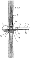
- the brush mechanism presented in Figures 1, 2, 3, and 4 has the following parts and points: a driving axle 1, which is comprised of the casing 1a, the axle 1b, the end with the brush 1c, the sleeve 1d, the bearing 1e, the outer sleeve 1f, and the clamp 1g. Additionally, there is the brush 2, which is comprised of the center part 2a, hole 2d, retainer 2c, stopper 2d, the smaller diameter 2e, and the bigger diameter 2f. Additionally, the figures illustrate the projection 3 and the blocking element 4.
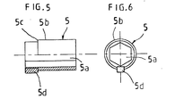
- FIGS 5 and 6 illustrate adapting piece 5, which is comprised of an inner hole 5a, outer surface 5b, retainer 5c and stopper 5d.
- the brush 2 used in a brush mechanism formed in accordance with the figures is placed at least partially overlapping the casing 1a of the driving axle 1, or the brush 2 is placed entirely overlapping the casing 1a of the driving axle 1.
- the brush 2 has a center part 2a which has a hole 2b in it. Additionally, the hole 2b contains a retainer 2c, which prevents the longitudinal movement of the brush's 2 driving axle 1 in at least one direction.
- the retainer 2c is formed out of a stop which is inside the hole 2b.
- the smaller diameter measurement 2e of the hole 2b is essentially smaller than the greater diameter measurement 2f of the hole 2b.
- a stopper 2d is inside of the hole 2b.
- the stopper 2d is a key slot.
- the center part 2a of the brush 2 of the brush mechanism can be advantageously produced of plastic, some mixture thereof, or corresponding material.
- the method of production and raw materials used are the same as those previously used in producing brushes.
- the hole 2b, retainer 2c and stopper 2d can be worked, for example, with conventional metal and plastic-working machinery, or most advantageously, they can be manufactured, for example, in connection with the press casting of the center part 2a.
- the center part 2a of the brush 2 has a projection 3, which is formed onto the center part 2a, from which it essentially extends outwards and is comprised of a peg which is attached to the center part 2a.
- the projection 3 can be advantageously made out of a cylindrical metal peg, one end of which has been made with an external thread, and the other end of which can be rounded.
- an internal thread is made in the outer shell of the center part 2a of the brush 2 near the end on the side with the driving axle 1, and advantageously so that when the projection 3 is screwed into place, it is at an angle to the driving axle 1.
- the angular position causes the projection 3 to catch in the downward joining corners of the air-conditioning ducts, which causes the brush 2 to jump free.
- the projection 3 can also be made of a nylon bar or a plastic cap can be put onto a metal peg, so that scratching of the air-conditioning ducts will not occur.
- the projection 3 can also be attached with a conventional type of glue.
- the outer sleeve 1f on the opposite end of the driving axle 1, has an external thread for the blocking element 4.
- the retainer 5c used to prevent the longitudinal movement of the adapting piece 5 of the brush 2 in at least one direction, is on the outer surface 5b of the adapting piece 5.
- This retainer 5c is a stop, which is formed from two different outside diameters, between which exists an intervening surface where the stop is formed.
- the stopper 5d which restricts the free rotation of the brush 2, is located on the outer surface 5b of the adapting piece 5.
- the outer sleeve 1f and the adapting piece 5 can be produced from conventional metals using conventional manufacturing techniques and machinery.
- the stopper 5d of the adapting piece 5 can be made, for example, using a wedge key which can be glued in place.
- a brush head formed in accordance with the invention is assembled in the following way.
- the casing 1a is underneath the sleeve 1d, which is placed on the end of the driving axle 1 and through which the end of the axle 1b passes.
- the bearing 1e is placed on the axle 1b, after which the outer sleeve 1f is placed against the bearing 1e.
- the outer sleeve 1f is attached to the axle 1b in such a way that it cannot rotate using the clamp 1g.
- the clamp 1g is an Allen screw.
- the brush 2 is placed onto the outer sleeve 1f, such that the retainer 2c (stop) of the brush 2 comes against the stop of the sleeve 1f.
- the end of the clamp 1g In placing the brush 2 on the sleeve 1f, the end of the clamp 1g must come against the stopper 2d of the brush 2, so that the brush 2 is not able to rotate freely.
- the blocking element 4 is turned onto the end of the outer sleeve 1f on the external thread, so that the brush 2 is locked in place.
- the bearing 1e reduces the parallel stress exerted on the driving axle 1 and facilitates the rotation of the brush 2.
- the blocking element 4 can be made using a conventional method, for example, out of plastic.
- the blocking element 4 is unscrewed manually, the brush is pulled away and replaced with a new brush. After this, the blocking element 4 is screwed back on manually. The blocking element 4 does not become unscrewed because the brush 2 and the outer sleeve 1f rotate together as one, so that the blocking element 4 is not subject to the force of rotation.
- a mechanism formed in accordance with the invention is used in the same way as other previous conventional air-conditioner duct cleaning brushes.
Landscapes
- Cleaning In General (AREA)
- Brushes (AREA)
- Mechanical Treatment Of Semiconductor (AREA)
- Electrical Discharge Machining, Electrochemical Machining, And Combined Machining (AREA)
- Finish Polishing, Edge Sharpening, And Grinding By Specific Grinding Devices (AREA)
Claims (10)
- Un mécanisme de brosse conçu spécialement pour le nettoyage de l'intérieur des conduits de climatisation, comprenant une brosse (2) et un arbre de transmission (1) pour la rotation de la brosse (2), le boítier dudit arbre de transmission (1) contenant un arbre qui a été conçu pour faire tourner la brosse (2), caractérisé en ce que la brosse (2) dépasse au moins partiellement le boítier de l'arbre de transmission (1).
- Un mécanisme de brosse constitué conformément à la revendication 1, caractérisé en ce que la brosse (2) dépasse entièrement l'arbre de transmission (1).
- Un mécanisme de brosse suivant la revendication 1, caractérisé en ce que la brosse (2) comprend une partie centrale (2a), à l'intérieur de laquelle il y a une ouverture (2b) contenant une butée (2c) qui empêche le mouvement longitudinal de l'arbre de transmission (1) de la brosse (2) dans au moins une direction.
- Un mécanisme de brosse constitué conformément à la revendication 3, caractérisé en ce que la butée (2c) est formée d'un arrêt qui se trouve à l'intérieur de l'ouverture (2b).
- Un mécanisme de brosse constitué conformément à la revendication 4, caractérisé en ce que le plus petit diamètre (2e) de l'ouverture (2b) est essentiellement plus petit que le diamètre plus grand (2f) de l'ouverture (2b).
- Un mécanisme de brosse constitué conformément à la revendication 3, caractérisé en ce que l'arrêt (2d), qui avantageusement est une entrée de serrure, est à l'intérieur de l'ouverture (2b).
- Un mécanisme de brosse constitué conformément à la revendication 3, caractérisé en ce qu'il y a une projection (3) dans la partie centrale (2a) de la brosse (2).
- Un mécanisme de brosse constitué conformément à la revendication 7, caractérisé en ce qu'une saillie (3) est formée sur la partie centrale 2a, de laquelle elle s'étend essentiellement vers l'extérieur et qui est constituée d'une cheville qui est fixée sur la partie centrale 2a.
- Un mécanisme de brosse constitué conformément à l'une des revendications de 1 à 8, caractérisé en ce qu'il comprend un adaptateur (5) sur la surface extérieure (5b) duquel est située une butée (5c) destinée à empêcher le mouvement longitudinal de la pièce d'adaptation (5) de la brosse au moins dans une direction.
- Un mécanisme de brosse constitué conformément à la revendication 9, caractérisé en ce qu'il y a un frein (5d) sur la surface extérieure (5b) de l'adaptateur (5) pour empêcher la rotation sans restriction de la brosse (2).
Applications Claiming Priority (2)
| Application Number | Priority Date | Filing Date | Title |
|---|---|---|---|
| FI990416A FI108839B (fi) | 1999-02-17 | 1999-02-26 | Harjan kiinnitysmenetelmä, harja, käyttöakseli ja sovitusosa |
| FI990416 | 1999-02-26 |
Publications (3)
| Publication Number | Publication Date |
|---|---|
| EP1031296A2 EP1031296A2 (fr) | 2000-08-30 |
| EP1031296A3 EP1031296A3 (fr) | 2001-01-17 |
| EP1031296B1 true EP1031296B1 (fr) | 2004-09-29 |
Family
ID=8553964
Family Applications (1)
| Application Number | Title | Priority Date | Filing Date |
|---|---|---|---|
| EP00660035A Expired - Lifetime EP1031296B1 (fr) | 1999-02-26 | 2000-02-28 | Dispositif de brossage |
Country Status (3)
| Country | Link |
|---|---|
| EP (1) | EP1031296B1 (fr) |
| AT (1) | ATE277543T1 (fr) |
| DE (1) | DE60014211T2 (fr) |
Family Cites Families (6)
| Publication number | Priority date | Publication date | Assignee | Title |
|---|---|---|---|---|
| US1428408A (en) * | 1921-11-30 | 1922-09-05 | John A White | Quick-detachable coupling |
| FI834468L (fi) * | 1983-12-07 | 1985-06-08 | Vilho Ilmari Hinkkanen | Rensningsanordning foer ventilationskanaler. |
| US4792363A (en) * | 1988-02-01 | 1988-12-20 | Franklin Jr Smead P | Vent cleaning system |
| US5383243A (en) * | 1992-11-27 | 1995-01-24 | Thacker; Gregory | Duct brush |
| US5735016A (en) * | 1994-10-21 | 1998-04-07 | Clean-Aire International, Inc. | Duct cleaning apparatus |
| US5619767A (en) * | 1995-10-16 | 1997-04-15 | Larson; Mark C. | Targetable-action stationary pot-scrubbing machine |
-
2000
- 2000-02-28 DE DE60014211T patent/DE60014211T2/de not_active Expired - Lifetime
- 2000-02-28 EP EP00660035A patent/EP1031296B1/fr not_active Expired - Lifetime
- 2000-02-28 AT AT00660035T patent/ATE277543T1/de not_active IP Right Cessation
Also Published As
| Publication number | Publication date |
|---|---|
| DE60014211D1 (de) | 2004-11-04 |
| EP1031296A2 (fr) | 2000-08-30 |
| ATE277543T1 (de) | 2004-10-15 |
| EP1031296A3 (fr) | 2001-01-17 |
| DE60014211T2 (de) | 2006-02-16 |
Similar Documents
| Publication | Publication Date | Title |
|---|---|---|
| US7269874B2 (en) | Cleaning device for cleaning ducts and pipes | |
| US5599233A (en) | Coaxial drive cable centering apparatus | |
| DE4205265C1 (en) | Rotary brush with brush holder and circular brush - has bristles on flexible brush strip, axial arms, and radial flanges | |
| US4777691A (en) | Motor driven brush assembly for vacuum cleaner | |
| US12186863B2 (en) | Drill attachment | |
| CN108294705A (zh) | 防毛发缠绕电动刷 | |
| US5058327A (en) | Tubing and fitting stripper | |
| EP1031296B1 (fr) | Dispositif de brossage | |
| US2158577A (en) | Sewer cleaning tool | |
| US5611109A (en) | Cleaning roller for the suction head of a vacuum cleaning device | |
| US20230135122A1 (en) | Plumber Rotor Machine Helper Device | |
| CN213175473U (zh) | 一种带限位功能的卷式窗帘制头 | |
| FI108839B (fi) | Harjan kiinnitysmenetelmä, harja, käyttöakseli ja sovitusosa | |
| CN212438481U (zh) | 一种防缠绕机构、滚刷、自动清洁设备 | |
| US20060249177A1 (en) | Duct Cleaning Brush | |
| KR100655204B1 (ko) | 다목적 소형선풍기 | |
| US5606759A (en) | Brush assembly of a cup washing machine | |
| US4468006A (en) | Continuous winch | |
| FI112178B (fi) | Harjapään kiinnitysmenetelmä käyttöakselin akseliin ja sen ulkovaippaan | |
| KR19980043373U (ko) | 덕트청소용 로봇청소기의 회전브러시 | |
| ITMI961092A1 (it) | Piastra girevole a motore con utensili di pulizia per una macchina per pulire pavimenti | |
| CN111387893B (zh) | 一种防缠绕机构、滚刷、自动清洁设备 | |
| JP5026894B2 (ja) | 回転ロータ | |
| JP3022726B2 (ja) | オーニング装置 | |
| JPS6139741Y2 (fr) |
Legal Events
| Date | Code | Title | Description |
|---|---|---|---|
| PUAI | Public reference made under article 153(3) epc to a published international application that has entered the european phase |
Free format text: ORIGINAL CODE: 0009012 |
|
| AK | Designated contracting states |
Kind code of ref document: A2 Designated state(s): AT BE CH CY DE DK ES FI FR GB GR IE IT LI LU MC NL PT SE |
|
| AX | Request for extension of the european patent |
Free format text: AL;LT;LV;MK;RO;SI |
|
| PUAL | Search report despatched |
Free format text: ORIGINAL CODE: 0009013 |
|
| AK | Designated contracting states |
Kind code of ref document: A3 Designated state(s): AT BE CH CY DE DK ES FI FR GB GR IE IT LI LU MC NL PT SE |
|
| AX | Request for extension of the european patent |
Free format text: AL;LT;LV;MK;RO;SI |
|
| RIC1 | Information provided on ipc code assigned before grant |
Free format text: 7A 46B 13/00 A, 7A 46B 5/06 B |
|
| 17P | Request for examination filed |
Effective date: 20010709 |
|
| AKX | Designation fees paid |
Free format text: AT BE CH CY DE DK ES FI FR GB GR IE IT LI LU MC NL PT SE |
|
| 17Q | First examination report despatched |
Effective date: 20030905 |
|
| GRAP | Despatch of communication of intention to grant a patent |
Free format text: ORIGINAL CODE: EPIDOSNIGR1 |
|
| GRAS | Grant fee paid |
Free format text: ORIGINAL CODE: EPIDOSNIGR3 |
|
| GRAA | (expected) grant |
Free format text: ORIGINAL CODE: 0009210 |
|
| AK | Designated contracting states |
Kind code of ref document: B1 Designated state(s): AT BE CH CY DE DK ES FI FR GB GR IE IT LI LU MC NL PT SE |
|
| PG25 | Lapsed in a contracting state [announced via postgrant information from national office to epo] |
Ref country code: IT Free format text: LAPSE BECAUSE OF FAILURE TO SUBMIT A TRANSLATION OF THE DESCRIPTION OR TO PAY THE FEE WITHIN THE PRESCRIBED TIME-LIMIT;WARNING: LAPSES OF ITALIAN PATENTS WITH EFFECTIVE DATE BEFORE 2007 MAY HAVE OCCURRED AT ANY TIME BEFORE 2007. THE CORRECT EFFECTIVE DATE MAY BE DIFFERENT FROM THE ONE RECORDED. Effective date: 20040929 Ref country code: NL Free format text: LAPSE BECAUSE OF FAILURE TO SUBMIT A TRANSLATION OF THE DESCRIPTION OR TO PAY THE FEE WITHIN THE PRESCRIBED TIME-LIMIT Effective date: 20040929 Ref country code: LI Free format text: LAPSE BECAUSE OF FAILURE TO SUBMIT A TRANSLATION OF THE DESCRIPTION OR TO PAY THE FEE WITHIN THE PRESCRIBED TIME-LIMIT Effective date: 20040929 Ref country code: CH Free format text: LAPSE BECAUSE OF FAILURE TO SUBMIT A TRANSLATION OF THE DESCRIPTION OR TO PAY THE FEE WITHIN THE PRESCRIBED TIME-LIMIT Effective date: 20040929 Ref country code: BE Free format text: LAPSE BECAUSE OF FAILURE TO SUBMIT A TRANSLATION OF THE DESCRIPTION OR TO PAY THE FEE WITHIN THE PRESCRIBED TIME-LIMIT Effective date: 20040929 Ref country code: FI Free format text: LAPSE BECAUSE OF FAILURE TO SUBMIT A TRANSLATION OF THE DESCRIPTION OR TO PAY THE FEE WITHIN THE PRESCRIBED TIME-LIMIT Effective date: 20040929 Ref country code: AT Free format text: LAPSE BECAUSE OF FAILURE TO SUBMIT A TRANSLATION OF THE DESCRIPTION OR TO PAY THE FEE WITHIN THE PRESCRIBED TIME-LIMIT Effective date: 20040929 Ref country code: ES Free format text: LAPSE BECAUSE OF FAILURE TO SUBMIT A TRANSLATION OF THE DESCRIPTION OR TO PAY THE FEE WITHIN THE PRESCRIBED TIME-LIMIT Effective date: 20040929 |
|
| REG | Reference to a national code |
Ref country code: GB Ref legal event code: FG4D |
|
| REG | Reference to a national code |
Ref country code: CH Ref legal event code: EP |
|
| REG | Reference to a national code |
Ref country code: IE Ref legal event code: FG4D |
|
| REF | Corresponds to: |
Ref document number: 60014211 Country of ref document: DE Date of ref document: 20041104 Kind code of ref document: P |
|
| REG | Reference to a national code |
Ref country code: SE Ref legal event code: TRGR |
|
| PG25 | Lapsed in a contracting state [announced via postgrant information from national office to epo] |
Ref country code: DK Free format text: LAPSE BECAUSE OF FAILURE TO SUBMIT A TRANSLATION OF THE DESCRIPTION OR TO PAY THE FEE WITHIN THE PRESCRIBED TIME-LIMIT Effective date: 20041229 Ref country code: GR Free format text: LAPSE BECAUSE OF FAILURE TO SUBMIT A TRANSLATION OF THE DESCRIPTION OR TO PAY THE FEE WITHIN THE PRESCRIBED TIME-LIMIT Effective date: 20041229 |
|
| PG25 | Lapsed in a contracting state [announced via postgrant information from national office to epo] |
Ref country code: IE Free format text: LAPSE BECAUSE OF NON-PAYMENT OF DUE FEES Effective date: 20050228 Ref country code: CY Free format text: LAPSE BECAUSE OF FAILURE TO SUBMIT A TRANSLATION OF THE DESCRIPTION OR TO PAY THE FEE WITHIN THE PRESCRIBED TIME-LIMIT Effective date: 20050228 Ref country code: MC Free format text: LAPSE BECAUSE OF NON-PAYMENT OF DUE FEES Effective date: 20050228 Ref country code: LU Free format text: LAPSE BECAUSE OF NON-PAYMENT OF DUE FEES Effective date: 20050228 |
|
| NLV1 | Nl: lapsed or annulled due to failure to fulfill the requirements of art. 29p and 29m of the patents act | ||
| REG | Reference to a national code |
Ref country code: CH Ref legal event code: PL |
|
| PLBE | No opposition filed within time limit |
Free format text: ORIGINAL CODE: 0009261 |
|
| STAA | Information on the status of an ep patent application or granted ep patent |
Free format text: STATUS: NO OPPOSITION FILED WITHIN TIME LIMIT |
|
| ET | Fr: translation filed | ||
| 26N | No opposition filed |
Effective date: 20050630 |
|
| REG | Reference to a national code |
Ref country code: IE Ref legal event code: MM4A |
|
| PG25 | Lapsed in a contracting state [announced via postgrant information from national office to epo] |
Ref country code: PT Free format text: LAPSE BECAUSE OF NON-PAYMENT OF DUE FEES Effective date: 20050228 |
|
| PGFP | Annual fee paid to national office [announced via postgrant information from national office to epo] |
Ref country code: GB Payment date: 20131216 Year of fee payment: 15 Ref country code: SE Payment date: 20131216 Year of fee payment: 15 |
|
| GBPC | Gb: european patent ceased through non-payment of renewal fee |
Effective date: 20150228 |
|
| PG25 | Lapsed in a contracting state [announced via postgrant information from national office to epo] |
Ref country code: SE Free format text: LAPSE BECAUSE OF NON-PAYMENT OF DUE FEES Effective date: 20150301 |
|
| REG | Reference to a national code |
Ref country code: SE Ref legal event code: EUG |
|
| PG25 | Lapsed in a contracting state [announced via postgrant information from national office to epo] |
Ref country code: GB Free format text: LAPSE BECAUSE OF NON-PAYMENT OF DUE FEES Effective date: 20150228 |
|
| REG | Reference to a national code |
Ref country code: FR Ref legal event code: PLFP Year of fee payment: 17 |
|
| REG | Reference to a national code |
Ref country code: FR Ref legal event code: PLFP Year of fee payment: 18 |
|
| REG | Reference to a national code |
Ref country code: FR Ref legal event code: PLFP Year of fee payment: 19 |
|
| PGFP | Annual fee paid to national office [announced via postgrant information from national office to epo] |
Ref country code: FR Payment date: 20180220 Year of fee payment: 19 |
|
| PGFP | Annual fee paid to national office [announced via postgrant information from national office to epo] |
Ref country code: DE Payment date: 20180425 Year of fee payment: 19 |
|
| REG | Reference to a national code |
Ref country code: DE Ref legal event code: R119 Ref document number: 60014211 Country of ref document: DE |
|
| PG25 | Lapsed in a contracting state [announced via postgrant information from national office to epo] |
Ref country code: DE Free format text: LAPSE BECAUSE OF NON-PAYMENT OF DUE FEES Effective date: 20190903 |
|
| PG25 | Lapsed in a contracting state [announced via postgrant information from national office to epo] |
Ref country code: FR Free format text: LAPSE BECAUSE OF NON-PAYMENT OF DUE FEES Effective date: 20190228 |