EP1031392B1 - Herstellungsverfahren und -Vorrichtung für ein Steuerungssystem in einem selektiv ablagernden Modellierungssystem - Google Patents
Herstellungsverfahren und -Vorrichtung für ein Steuerungssystem in einem selektiv ablagernden Modellierungssystem Download PDFInfo
- Publication number
- EP1031392B1 EP1031392B1 EP00301433A EP00301433A EP1031392B1 EP 1031392 B1 EP1031392 B1 EP 1031392B1 EP 00301433 A EP00301433 A EP 00301433A EP 00301433 A EP00301433 A EP 00301433A EP 1031392 B1 EP1031392 B1 EP 1031392B1
- Authority
- EP
- European Patent Office
- Prior art keywords
- job
- jobs
- client computer
- job queue
- rapid prototyping
- Prior art date
- Legal status (The legal status is an assumption and is not a legal conclusion. Google has not performed a legal analysis and makes no representation as to the accuracy of the status listed.)
- Expired - Lifetime
Links
Images


Classifications
-
- B—PERFORMING OPERATIONS; TRANSPORTING
- B29—WORKING OF PLASTICS; WORKING OF SUBSTANCES IN A PLASTIC STATE IN GENERAL
- B29C—SHAPING OR JOINING OF PLASTICS; SHAPING OF MATERIAL IN A PLASTIC STATE, NOT OTHERWISE PROVIDED FOR; AFTER-TREATMENT OF THE SHAPED PRODUCTS, e.g. REPAIRING
- B29C64/00—Additive manufacturing, i.e. manufacturing of three-dimensional [3D] objects by additive deposition, additive agglomeration or additive layering, e.g. by 3D printing, stereolithography or selective laser sintering
- B29C64/40—Structures for supporting 3D objects during manufacture and intended to be sacrificed after completion thereof
-
- B—PERFORMING OPERATIONS; TRANSPORTING
- B29—WORKING OF PLASTICS; WORKING OF SUBSTANCES IN A PLASTIC STATE IN GENERAL
- B29C—SHAPING OR JOINING OF PLASTICS; SHAPING OF MATERIAL IN A PLASTIC STATE, NOT OTHERWISE PROVIDED FOR; AFTER-TREATMENT OF THE SHAPED PRODUCTS, e.g. REPAIRING
- B29C64/00—Additive manufacturing, i.e. manufacturing of three-dimensional [3D] objects by additive deposition, additive agglomeration or additive layering, e.g. by 3D printing, stereolithography or selective laser sintering
- B29C64/10—Processes of additive manufacturing
- B29C64/106—Processes of additive manufacturing using only liquids or viscous materials, e.g. depositing a continuous bead of viscous material
- B29C64/112—Processes of additive manufacturing using only liquids or viscous materials, e.g. depositing a continuous bead of viscous material using individual droplets, e.g. from jetting heads
-
- B—PERFORMING OPERATIONS; TRANSPORTING
- B33—ADDITIVE MANUFACTURING TECHNOLOGY
- B33Y—ADDITIVE MANUFACTURING, i.e. MANUFACTURING OF THREE-DIMENSIONAL [3D] OBJECTS BY ADDITIVE DEPOSITION, ADDITIVE AGGLOMERATION OR ADDITIVE LAYERING, e.g. BY 3D PRINTING, STEREOLITHOGRAPHY OR SELECTIVE LASER SINTERING
- B33Y50/00—Data acquisition or data processing for additive manufacturing
- B33Y50/02—Data acquisition or data processing for additive manufacturing for controlling or regulating additive manufacturing processes
-
- B—PERFORMING OPERATIONS; TRANSPORTING
- B29—WORKING OF PLASTICS; WORKING OF SUBSTANCES IN A PLASTIC STATE IN GENERAL
- B29C—SHAPING OR JOINING OF PLASTICS; SHAPING OF MATERIAL IN A PLASTIC STATE, NOT OTHERWISE PROVIDED FOR; AFTER-TREATMENT OF THE SHAPED PRODUCTS, e.g. REPAIRING
- B29C2948/00—Indexing scheme relating to extrusion moulding
- B29C2948/92—Measuring, controlling or regulating
- B29C2948/92504—Controlled parameter
- B29C2948/92609—Dimensions
- B29C2948/92628—Width or height
-
- B—PERFORMING OPERATIONS; TRANSPORTING
- B29—WORKING OF PLASTICS; WORKING OF SUBSTANCES IN A PLASTIC STATE IN GENERAL
- B29C—SHAPING OR JOINING OF PLASTICS; SHAPING OF MATERIAL IN A PLASTIC STATE, NOT OTHERWISE PROVIDED FOR; AFTER-TREATMENT OF THE SHAPED PRODUCTS, e.g. REPAIRING
- B29C2948/00—Indexing scheme relating to extrusion moulding
- B29C2948/92—Measuring, controlling or regulating
- B29C2948/92504—Controlled parameter
- B29C2948/92609—Dimensions
- B29C2948/92638—Length
-
- B—PERFORMING OPERATIONS; TRANSPORTING
- B29—WORKING OF PLASTICS; WORKING OF SUBSTANCES IN A PLASTIC STATE IN GENERAL
- B29C—SHAPING OR JOINING OF PLASTICS; SHAPING OF MATERIAL IN A PLASTIC STATE, NOT OTHERWISE PROVIDED FOR; AFTER-TREATMENT OF THE SHAPED PRODUCTS, e.g. REPAIRING
- B29C2948/00—Indexing scheme relating to extrusion moulding
- B29C2948/92—Measuring, controlling or regulating
- B29C2948/92504—Controlled parameter
- B29C2948/92704—Temperature
-
- B—PERFORMING OPERATIONS; TRANSPORTING
- B29—WORKING OF PLASTICS; WORKING OF SUBSTANCES IN A PLASTIC STATE IN GENERAL
- B29C—SHAPING OR JOINING OF PLASTICS; SHAPING OF MATERIAL IN A PLASTIC STATE, NOT OTHERWISE PROVIDED FOR; AFTER-TREATMENT OF THE SHAPED PRODUCTS, e.g. REPAIRING
- B29C2948/00—Indexing scheme relating to extrusion moulding
- B29C2948/92—Measuring, controlling or regulating
- B29C2948/92819—Location or phase of control
- B29C2948/9298—Start-up, shut-down or parameter setting phase; Emergency shut-down; Material change; Test or laboratory equipment or studies
-
- B—PERFORMING OPERATIONS; TRANSPORTING
- B29—WORKING OF PLASTICS; WORKING OF SUBSTANCES IN A PLASTIC STATE IN GENERAL
- B29C—SHAPING OR JOINING OF PLASTICS; SHAPING OF MATERIAL IN A PLASTIC STATE, NOT OTHERWISE PROVIDED FOR; AFTER-TREATMENT OF THE SHAPED PRODUCTS, e.g. REPAIRING
- B29C48/00—Extrusion moulding, i.e. expressing the moulding material through a die or nozzle which imparts the desired form; Apparatus therefor
- B29C48/03—Extrusion moulding, i.e. expressing the moulding material through a die or nozzle which imparts the desired form; Apparatus therefor characterised by the shape of the extruded material at extrusion
- B29C48/12—Articles with an irregular circumference when viewed in cross-section, e.g. window profiles
-
- B—PERFORMING OPERATIONS; TRANSPORTING
- B29—WORKING OF PLASTICS; WORKING OF SUBSTANCES IN A PLASTIC STATE IN GENERAL
- B29C—SHAPING OR JOINING OF PLASTICS; SHAPING OF MATERIAL IN A PLASTIC STATE, NOT OTHERWISE PROVIDED FOR; AFTER-TREATMENT OF THE SHAPED PRODUCTS, e.g. REPAIRING
- B29C48/00—Extrusion moulding, i.e. expressing the moulding material through a die or nozzle which imparts the desired form; Apparatus therefor
- B29C48/03—Extrusion moulding, i.e. expressing the moulding material through a die or nozzle which imparts the desired form; Apparatus therefor characterised by the shape of the extruded material at extrusion
- B29C48/13—Articles with a cross-section varying in the longitudinal direction, e.g. corrugated pipes
-
- G—PHYSICS
- G05—CONTROLLING; REGULATING
- G05B—CONTROL OR REGULATING SYSTEMS IN GENERAL; FUNCTIONAL ELEMENTS OF SUCH SYSTEMS; MONITORING OR TESTING ARRANGEMENTS FOR SUCH SYSTEMS OR ELEMENTS
- G05B2219/00—Program-control systems
- G05B2219/30—Nc systems
- G05B2219/31—From computer integrated manufacturing till monitoring
- G05B2219/31378—Queue control
-
- G—PHYSICS
- G05—CONTROLLING; REGULATING
- G05B—CONTROL OR REGULATING SYSTEMS IN GENERAL; FUNCTIONAL ELEMENTS OF SUCH SYSTEMS; MONITORING OR TESTING ARRANGEMENTS FOR SUCH SYSTEMS OR ELEMENTS
- G05B2219/00—Program-control systems
- G05B2219/30—Nc systems
- G05B2219/49—Nc machine tool, till multiple
- G05B2219/49021—Deposit layer, machine, mill layer, then new layer, SDM solid deposit manufacting
Definitions
- This invention relates to techniques for a control system in a selective deposition modeling system used for forming three-dimensional (3D) objects on substantially a layer-by-layer basis with enhanced resolution.
- the invention more particularly relates to techniques for use in controlling jobs corresponding to three-dimensional objects to be built in a selective deposition modeling system.
- Rapid Prototyping and Manufacturing is the name given to a field of technologies that can be used to form three-dimensional objects rapidly and automatically from three-dimensional computer data representing the objects.
- RP&M can be considered to include three classes of technologies: (1) Stereolithography, (2) Laminated Object Manufacturing, and (3) Selective Deposition Modeling.
- the stereolithography class of technologies create three-dimensional objects based on the successive formation of layers of a fluid-like medium adjacent to previously formed layers of medium and the selective solidification of those layers according to cross-sectional data representing successive slices of the three-dimensional object in order to form and adhere laminae.
- One specific stereolithography technology is known simply as stereolithography and uses a liquid medium which is selectively solidified by exposing it to prescribed stimulation.
- the liquid medium is typically a photopolymer and the prescribed stimulation is typically visible or ultraviolet electromagnetic radiation.
- Liquid-based stereolithography is disclosed in various patents, applications, and publications of which a number are briefly described in the Related Applications section hereinafter.
- Another stereolithography technology is known as Selective Laser Sintering (SLS).
- SLS is based on the selective solidification of layers of a powdered medium by exposing the layers to infrared electromagnetic radiation to sinter or fuse the particles. SLS is described in US Patent No. 4,863,538 issued September 5, 1989 to Deckard.
- a third technology is known as Three-dimensional Printing (3DP). 3DP is based on-the selective solidification of layers of a powdered medium which are solidified by the selective deposition of a binder thereon. 3DP is described in US Patent No. 5,204,055 issued April 20, 1993 to Sachs.
- Laminated Object Manufacturing, LOM techniques involve the formation of three-dimensional objects by the stacking, adhering, and selective cutting of sheets of material, in a selected order, according to the cross-sectional data representing the three-dimensional object to be formed.
- LOM is described in US Patent Nos. 4,752,352 issued June 21, 1988 to Feygin; and 5,015,312 issued May 14, 1991 to Kinzie, and in PCT Publication No. WO 95-18009 published July 6, 1995 naming Morita as an inventor.
- Selective Deposition Modeling involves the build-up of three-dimensional objects by selectively depositing solidifiable material on a lamina-by-lamina basis according to cross-sectional data representing slices of the three-dimensional object.
- FDM Fused Deposition Modeling
- FDM involves the extrusion of streams of heated, flowable material which solidify as they are dispensed onto the previously formed laminae of the object.
- FDM is described in US Patent No. 5,121,329 issued June 9, 1992 to Crump.
- Another technique is called Ballistic Particle Manufacturing, BPM, which uses a 5-axis, ink-jet dispenser to direct particles of a material onto previously solidified layers of the object.
- BPM is described in PCT publication numbers WO 96-12607 published May 2, 1996 naming Brown as an inventor, WO 96-12608 published May 2, 1996 naming Brown as an inventor; WO 96-12609 published May 2, 1996 naming Menhennett as an inventor; and WO 96-12610 published May 2, 1996 naming Menhennett as an inventor, all assigned to BPM Technology, Inc.
- a third technique is called Multijet Modeling and involves the selective deposition of droplets of material from multiple ink jet orifices to speed the building process. Multijet Modeling is described in PCT Publication Nos. WO 97-11835 published April 3, 1997 naming Leyden as an inventor, and WO 97-11837 published April 3, 1997 naming Earl as an inventor (both assigned to 3D Systems, Inc. as is the instant application).
- a fourth example is Thermal Stereolithography (TSL) as described in U.S. Patent No. 5,141,680 issued August 25, 1992 to Almquist et al.
- WO97/19798 discloses a system for solid prototyping that exists on a local area network, which is able to accept spooled files from a server, handle queues of requests, and respond to queries with status information.
- a rapid prototyping system comprises:
- a method of creating a three-dimensional object in a rapid prototyping system comprises the steps of:
- Embodiments of the instant invention involve a number of techniques (including methods and apparatus) that can be used alone or in combination to address a number of problems associated with controlling jobs for forming 3D objects by Selective Deposition Modeling.
- Selective Deposition Modeling techniques the techniques described hereinafter can be applied in a variety of ways to the other RP&M technologies as described above to enhance system throughput by providing enhanced object generation techniques.
- the techniques described herein can be applied to Selective Deposition Modeling systems that use one or more building and/or support materials wherein one or more of the materials are selectively dispensed, wherein others may be dispensed non-selectively, and wherein elevated temperatures may or may not be used for all or part of the materials to aid in their selective deposition.
- the techniques can be applied to Selective Deposition Modeling systems wherein the building material may be a solid made to be melted on a hot plate, which material can be made to solidify after dispensing by causing the removal of the solvent (e.g. by heating the dispensed material, by dispensing the material into a partially evacuated (i.e. vacuum) building chamber, or by simply allowing sufficient time for the solvent to evaporate).
- various dispensing techniques may be used such as dispensing by single or multiple ink jet devices including hot melt ink jets, bubble jets, etc and continuous or semi-continuous flow, single or multiple orifice extrusion nozzles or heads.
- FIG. 1 A preferred apparatus for performing Selective Deposition Modeling is illustrated in Figures 1 and 2.
- the apparatus comprises a dispensing carriage 10 on which is situated dispensing head 12 (e.g. multi-orifice ink jet head) and planarizer (e.g., a rotating and/or heated roller) 14.
- the dispensing carriage 10 is supported and drivable back and forth in the X-direction, also known as the main scanning direction, adjacent a build platform 20.
- the spacing between the head 12 and the dispensing carriage 10 in Figure 1 is exaggerated for simplifying the present disclosure. In practice the spacing would be small enough to allow the planarizer 14 to contact material deposited on the build platform 20 by the head 12.
- the motion of the dispensing carriage 10 is under the control of a suitable drive motor and a control computer or microprocessor (not shown).
- one or more fans 15 for blowing air vertically down are mounted to help cool the dispensed material and substrate such that the desired building temperature is maintained.
- other mounting schemes for the fans and/or other cooling systems are possible including the use of misting devices for directing vaporizable liquids (e.g. water, alcohol, or solvents) onto the surface of the object. Cooling systems might involve active or passive techniques for removing heat and may be computer controlled in combination with temperature sensing devices to maintain the dispensed material within the desired building temperature range.
- the dispensing head 12 may be for example, a commercial print head configured for jetting color hot melt inks (e.g. thermal plastics or wax-like materials), and modified and/or controlled for use in a three-dimensional modeling system wherein the print head 12 undergoes back and forth movements and accelerations.
- the head is a 352 jet multi-color commercial print head produced by Tektronix, Inc.
- One group of jets comprises four jets 16 which, in a color print head, would represent four colors. Three jets are on the same X-line, and one jet at the end of the sequence of four jets is positioned slightly off of this X-line (i.e., on a different Y-dimension location from the other three jets).
- the print head 12 is supplied hot melt material in a flowable state from a reservoir (not shown) for selective jetting from the print head.
- all 352 jets on the print head 12 are computer controlled to selectively fire droplets when each orifice (i.e., jet) is appropriately located to dispense droplets onto desired locations of a build platform 20.
- commands are sent to each jet selectively commanding each one to fire (i.e., dispense a droplet) or not to fire (i.e., not to dispense a droplet) depending on jet position and desired locations for material deposition.
- firing commands are preferably sent simultaneously to all jets.
- the head is computer controlled so as to selectively fire the jets, to simultaneously emit droplets of the molten material through one or more jets.
- heads with a different numbers of jets can be used, different firing frequencies are possible and, in appropriate circumstances, non-simultaneous firing of the jets is possible.
- the print head 12 defines a pattern of orifices corresponding in number to the number of jets. With respect to Figure 1, the orifices are directed such that droplets of material are allowed to emit from the underside of the dispensing carriage 10.
- the dispensing head 12 i.e., the array of orifices
- the main scanning direction e.g. X-direction
- the N 352 individually controllable orifices, arranged in 88 groups of four jets.
- Each dispenser e.g., jet
- Each dispenser is equipped with a piezoelectric element which causes a pressure wave to propagate through the material when an electric firing pulse is applied to the element in accordance with well known ink jet head technology.
- the pressure wave causes a drop of material to be emitted from orifice.
- the 352 dispensers are controlled by the control computer which controls the rate and timing of the firing pulses applied to the individual dispenser and therefore the rate and timing of droplets being emitted from the orifices.
- One embodiment uses raster scanning to position the print head and orifices to dispense material at desired drop locations.
- the printing process for each layer is accomplished by a series of relative movements between the head and the desired drop locations on the build platform 20 or previously formed layer.
- Printing typically occurs as the head relatively moves in a main scanning direction. This is followed by a movement of the build platform 20 in a secondary scanning direction (i.e., Y-direction), while no dispensing occurs.
- the dispensing carriage 10 moves in a reverse main scanning direction (i.e., opposite X-direction from the direction of movement while dispensing in the previous pass), while dispensing occurs. This is followed by another scan in the main scanning direction in which dispensing again occurs. Alternatively, dispensing may occur in only one X-direction. This process occurs repeatedly until the layer is completely deposited. The procedure is then repeated for each subsequent layer.
- Other alternative embodiments may utilize vector scanning techniques or a combination of vector scanning and raster scanning.
- Other alternative embodiments may use substantially non-perpendicular main and secondary scanning directions along with techniques that result in proper placement of droplets.
- multiple prints heads may be used which lay end to end (extend in the secondary scanning direction) and/or which are stacked back to back (stacked in the main scanning direction).
- the print heads may have orifices aligned in the main scanning direction so that they print over the same lines or alternatively they may be offset from one another so as dispense material along different main scanning lines.
- the data defining deposition locations may not be located by pixels defining a rectangular grid but instead may be located by pixels laid out in some other pattern (e.g. offset or staggered pattern). More particularly, the deposition locations may be fully or partially varied from layer to layer in order to perform partial pixel drop location offsetting for an entire layer or for a portion of a layer based on the particulars of a region to be jetted.
- planarizer 14 comprises a heated rotating cylinder with a smooth surface. Its function is to melt, transfer and remove portions of the most recently dispensed layer of material, to smooth it out, to set a desired thickness for the last formed layer, and to set the net upper surface of the last formed layer to a desired level (i.e. the desired working surface or working level for forming a next lamina of the object).
- Numeral 22 identifies a layer of material which has just been deposited by the print head.
- the rotating cylinder planarizer 14 is mounted to the dispensing carriage 10 such that it is allowed to project from the underside of the platform by a sufficient amount in the Z-direction such that it contacts material 22 on build platform 20 at a desired level below the orifice plate (the spacing between the planarizer 14 and material 22 is exaggerated in Figure 1, to more clearly show elements of the system).
- the rotation of the planarizer cylinder sweeps material from the just-deposited layer, leaving a smooth surface.
- the just-deposited material adheres to the smooth, heated surface of the cylinder and is displaced until it contacts a wiper (not shown).
- the wiper is disposed to effectively "scrape" the material from the surface of the cylinder. This material, which is still flowable, is either disposed of or recycled.
- build platform 20 defines a surface on which is built the three-dimensional object or part layer-by-layer.
- This platform 20 is preferably supported for movement and driven back and forth in the Y-direction (i.e., index direction or secondary scanning direction) under computer control.
- the build platform 20 also is supported for movement and is driven up and down (typically progressively downward during the build process) in the Z-direction under computer control.
- the build platform 20 moves in the Z-direction relative to the print head 12, such that the last-built (i.e., dispensed and possibly planed) layer of the part is situated an appropriate amount below the orifice plate 18 of the print head 12.
- the print head 12 is moved one or more times over the XY build region (the head sweeps back and forth in the X direction, while the Y-stage translates the partially formed object in the Y-direction).
- the combination of the last formed layer of the object and any supports associated therewith define the working surface for deposition of the next lamina and any supports associated therewith.
- the jets of the print head are fired in a registered manner with previously dispensed layers to deposit material in a desired pattern and sequence for the building of the next lamina of the object.
- a portion of the dispensed material is removed by the planarizer in the manner discussed above.
- the X, Y and Z movements, dispensing, and planarizing are repeated to build up the object from a plurality of selectively dispensed and adhered layers.
- the step of planarization could be performed independently of the dispensing steps.
- the planarizer may not be used on all layers but instead may be used on selected or periodic layers.
- the print head is directed to trace a raster pattern.
- the raster pattern consists of a series of raster lines, R(1), R(2),..., R(N), running in the X-direction or main scanning direction and arrayed along the Y-direction (i.e. index direction or secondary scanning direction).
- the raster lines are spaced from one another by a distance d r , which, in an embodiment, is 1/300 inches (about 3.3 mils or about 83.8 ⁇ m).
- the first step includes alternating main scanning direction passes with secondary scanning direction movements of an amount equal to the desired raster line resolution until all raster lines between initial lines dispensed by two adjacent jets are scanned. Thereafter, a second step includes a large index direction increment is made. The first and second steps are repeated until the indexing direction increments, and lines scanned, are sufficient to deposit material on all raster lines required to form the object layer or cross-section (including any necessary supports for forming subsequent cross-sections).
- the firing of the ink jet orifices is controlled by a rectangular bit map maintained in a control computer or other memory device.
- the bit map consists of a grid of memory cells, in which each memory cell corresponds to a pixel of the working surface, and in which the rows of the grid extend in the main scanning direction (X-direction) and the columns of the grid extend in the secondary scanning direction (Y-direction).
- the width of (or distance between) the rows (spacing along the Y-direction) may be different from the width (or length of or distance between) of the columns (spacing along the X-direction) dictating that different data resolutions may exist along the X and Y directions.
- non-uniform pixel size is possible within a layer or between layers wherein one or both of the pixel width or length is varied by pixel position.
- other pixel alignment patterns are possible. For example, pixels on adjacent rows may be offset in the main scanning direction by a fractional amount of the spacing between pixels in the main scanning direction so that their center points do not align with the center points of the pixels in the neighboring rows. This fractional amount may be 1 ⁇ 2 so that their center points are aligned with the pixel boundaries of adjacent rows. It may be 1/3 or some other amount such that two or more intermediate rows of pixels are located between rows where pixels are realigned in the main scanning direction.
- pixel alignment might be dependent on the geometry of the object or support structure being dispensed.
- pixel alignment schemes can be implemented by modifying the pixel configuration or alternatively defining a higher resolution pixel arrangement (in X and/or Y) and using pixel firing patterns that do not fire on every pixel location but instead fire on selected spaced pixel locations which may vary according to a desired random, predetermined or object basis pattern.
- the data resolution in the main scanning direction may be defined in terms of Main Direction Pixels (MDPs).
- SDPs Secondary Direction Pixels
- SDP Secondary Direction Pixels
- the SDP may or may not be equivalent to spacing between raster lines and the MDP may or may not be equivalent to the spacing between successive drop locations along each raster line.
- the spacing between successive raster lines may be defined as Secondary Drop Locations (SDLs), while spacing between successive drop locations along each raster line may be defined as Main Drop Locations (MDLs). Similar to SDPs and MDPs, SDLs and MDLs may be defined in terms of drops per unit length or drop spacing.
- SDL and/or MDL is larger than SDP and MDP, respectively, more drops will need to be fired than that for which data exists, thus each pixel will need to be used in causing more than one droplet to be dispensed.
- the dispensing of these extra droplets can be done in one of two ways either by dispensing the droplets at intermediate points between the centers of successive pixels (i.e. intermediate dropping, "ID") or alternatively directly on top of pixel centers (i.e. direct dropping, "DD"). In either case this technique is called “overprinting” and results in faster build up of material and eases mechanical design constraints involving maximum scan speeds and acceleration rates since the same Z-build up can occur while moving the print head and/or object more slowly.
- SDL and/or MDL is less than SDP and/or MDP, respectfully, drops will be fired at fewer locations than those for which data exists, at least for a given pass of the print head. This data situation may be used to implement the offset pixel and/or non-uniform sized pixel techniques discussed above.
- the bit map is first loaded with data representative of the desired cross-section (as well as any supports which are desired to be built). Assuming, as with this embodiment, a single build and support material is being used, if it is desired to deposit material at a given pixel location, then the memory cell corresponding to that location is appropriately flagged (e.g. loaded with a binary "1") and if no material is to be deposited an opposite flag is used (e.g. a binary "0"). If multiple materials are used, cells corresponding to deposition sites are flagged appropriately to indicate not only drop location sites but also the material type to be deposited. For ease of data handling, compressed data defining an object or support region (e.g.
- on-off location points along each raster line can be booleaned with a fill pattern description to be used for the particular region to derive a final bit map representation used for firing the dispensing jets.
- the raster lines making up the grid are then assigned to individual orifices in the manner described earlier. Then, a particular orifice is directed to fire or not over a pixel depending on how the corresponding cell in the bit map is flagged.
- Figure 3 illustrates a preferred apparatus for communication between multiple client computers and a Selective Deposition Modeling system.
- Clients i.e., client computers
- the Selective Deposition Modeling system 46 is connected to the Selective Deposition Modeling system 46 via a network 50.
- Conventional systems typically require that a client computer connect to a print server, which stores a job queue of jobs and transmits the jobs to a modeling system.
- the job queue functions are implemented in a Selective Deposition Modeling system 48, which enables users to connect directly to the Selective Deposition Modeling system 48 via client computers 40, 42, and 44 to submit jobs to the job queue, to preview the job queue, and to manipulate the job queue.
- the client computers 40, 42, and 44 generally include, inter alia, a processor, random access memory (RAM), data storage devices (e.g., hard, floppy, and/or CD-ROM disk drives, etc.), data communications devices (e.g., modems, network interfaces, etc.), a monitor (e.g., CRT, LCD display, etc.), a mouse pointing device and a keyboard. It is envisioned that attached to the client computers 40, 42, and 44 may be other devices such as read only memory (ROM), a video card, bus interface, printers, etc. Those skilled in the art will recognize that any combination of the above components, or any number of different components, peripherals, and other devices, may be used with the client computers 40, 42, and 44.
- RAM random access memory
- data storage devices e.g., hard, floppy, and/or CD-ROM disk drives, etc.
- data communications devices e.g., modems, network interfaces, etc.
- monitor e.g., CRT,
- the Selective Deposition Modeling system 46 generally includes, inter alia, a processor, random access memory (RAM), data storage devices (e.g., hard, floppy, and/or CD-ROM disk drives, etc.), and data communications devices (e.g., modems, network interfaces, etc.). It is envisioned that attached to the Selective Deposition Modeling system 46 may be other devices, such as a monitor, a mouse, and a keyboard. Those skilled in the art will recognize that any combination of the above components, or any number of different components, peripherals, and other devices, may be used with the Selective Deposition Modeling system 46.
- RAM random access memory
- data storage devices e.g., hard, floppy, and/or CD-ROM disk drives, etc.
- data communications devices e.g., modems, network interfaces, etc.
- the client computers 40, 42, and 44 and the Selective Deposition Modeling system 46 operate under the control of an operating system (OS).
- OS operating system
- the operating system controls the execution of one or more computer programs at the client computers 40, 42, and 44 and Selective Deposition Modeling system 46.
- the present invention is generally implemented in these computer programs.
- the operating systems and computer programs are comprised of instructions which, when read and executed by the client computers 40, 42, and 44 and Selective Deposition Modeling system 46, cause the client computers 40, 42, and 44 and Selective Deposition Modeling system 46 to perform the steps necessary to implement and/or use the present invention.
- embodiments of the present invention may be implemented as a method, apparatus, or article of manufacture using standard programming and/or engineering techniques to produce software, firmware, hardware, or any combination thereof.
- article of manufacture (or alternatively, “computer program product”) as used herein is intended to encompass a computer program accessible from any computer-readable device, carrier, or media.
- FIG. 3 is not intended to limit the present invention. Indeed, those skilled in the art will recognize that other alternative hardware environments may be used without departing from the scope of the present invention.
- the Selective Deposition Modeling system 46 contains Selective Deposition Modeling system controls 48 of the present invention.
- the client computers 40, 42, and 44 are able to communicate directly with the Selective Deposition Modeling system 46 and provide commands to the Selective Deposition Modeling system controls 48.
- the client computers 40, 42, and 44 provide commands for building three-dimensional parts or objects. As discussed above, the firing of the ink jet orifices is controlled by a cross-section comprised of a rectangular bit map maintained in a control computer or other memory device. Each client computer 40, 42, and 44 is able to create the cross-sectional bit maps used to build three-dimensional objects, layer by layer (with each cross-section corresponding to a layer). The client computers 40, 42, and 44 transmit the bit maps to the Selective Deposition Modeling system 46.
- Each of the client computers 40, 42, and 44 maintains a local job queue. Each job has a job representing the object to be built.
- the Selective Deposition Modeling system 46 is unaware of the client computers' 40, 42, and 44 local job queues.
- the client computers 40, 42, and 44 are able to create a single job for multiple objects, for example a globe and a cube, as long as the objects fit on the build platform. Additionally, in one embodiment, overlap of the objects may be tolerated if, for example, the objects can be separated by supports.
- the client computers 40, 42, and 44 can store jobs in their local job queues and transmit commands to the Selective Deposition Modeling system 46 to have these jobs entered into the job queue controlled by the Selective Deposition Modeling system controls 48.
- the Selective Deposition Modeling system controls 48 provide controls for, among other things, managing the job queue.
- the job queue is stored and maintained by the Selective Deposition Modeling system controls 48.
- the job queue has a "head”, which is the front of the job queue, and a "bottom", which is the rear of the job queue.
- the Selective Deposition Modeling system controls 48 adds a job representing that object to the "bottom" of the job queue.
- the jobs could be stored into the job queue based on a priority scheme, such as an urgency level associated with each job, size of each job, source of each job, other factors suitable for defining a priority order, or combinations of such factors.
- the job queue contains jobs at different stages of being built. Some jobs are pending processing. These are jobs that have been added to the job queue, without further processing.
- the job queue also contains jobs that are being prepared. These are jobs that are selected for pre-processing, for example, while another object is being built on the build platform or during initialization of the system.
- the job queue also contains jobs that are being built. These are jobs that are being built on the build platform.
- the term "build” refers to a job that is about to be built. As will be discussed below, one "build" can comprise multiple jobs.
- the Selective Deposition Modeling system controls enable a user at a client computer to preview all of the jobs in the job queue. Whether or not a user at the client computer submitted a particular job, the user could preview the job. In an alternative embodiment, a particular user (e.g., an administrator) or client computer may be designated to be the only one with access to previewing all jobs. In another embodiment, a user may only preview jobs that the user submitted.
- an embodiment of the invention provides a list of the jobs and/or images of the jobs and enables a user to select a job for previewing, by, for example, using a mouse to "click" on the job in the list or on an image of a job.
- other suitable user interfaces may be used as an alternative to a mouse, inlcuding, but not limited to other forms of cursor control, such as touch screen, keyboard, or the like.
- the client computer sends a request to the Selective Deposition Modeling system 46 to preview jobs in the job queue.
- the Selective Deposition Modeling system 46 provides the client computer with a list of jobs in the job queue.
- the client computer then provides the Selective Deposition Modeling system 46 with data identifying a job in the list selected by a user.
- the Selective Deposition Modeling system controls 48 prepare the data in the job queue to be displayed on a monitor at the client computer in three-dimensional form.
- the Selective Deposition Modeling system controls 48 may use the bitmap associated with a job to provide this preview.
- the Selective Deposition Modeling system controls 48 transmit the data to the client computer.
- the data is displayed at the client computer for use by a user.
- the data displayed shows the object as it will be rendered by the Selective Deposition Modeling system 46. Additionally, if multiple objects from different jobs are combined, as will be discussed below, the Selective Deposition Modeling system controls 48 shows the combination of objects as they will be rendered.
- FIG 4 is a flow diagram illustrating steps performed by the Selective Deposition Modeling system controls 48 to enable previewing of a job.
- the Selective Deposition Modeling system controls 48 provide a list of jobs or images of the jobs to a client computer, as represented by Block 50, for example, in response to a request for such a list from the client computer.
- the Selective Deposition Modeling system controls 48 receive a selection of a job from the client computer, as represented by Block 52.
- the Selective Deposition Modeling system controls 48 prepares data to render the selected job in three-dimensional form, as illustrated by Block 54. Then, the Selective Deposition Modeling system controls 48 transmit the data to the client computer to render the selected job in three-dimensional form at the client computer, as represented by Block 56.
- the Selective Deposition Modeling system controls 48 enable users at client computers to manipulate a pending job in the job queue.
- the Selective Deposition Modeling system controls 48 enable a user to promote a job in the job queue to a specified position. Jobs are stored at the "bottom" of the job queue, and move up in the job queue as jobs ahead of them are processed.
- the jobs are processed in FIFO (first in, first out) order, however, as will be discussed below, in other embodiments the jobs are not processed in FIFO order.
- FIFO first in, first out
- the Selective Deposition Modeling system controls 48 also enable a user to demote a job to a specified position, ensuring that the job is processed after jobs that are stored behind the demoted job when jobs are selected for processing from the head of the job queue. Additionally, the Selective Deposition Modeling system controls 48 enable a user to send a job to the head of the job queue or to the bottom of the job queue. Moreover, the Selective Deposition Modeling system controls 48 enable a user to delete a job.
- a user at a client computer manipulates the job queue stored at the Selective Deposition Modeling system 46.
- the Selective Deposition Modeling system controls 48 enable any user to manipulate the job queue.
- only a designated user e.g., a system administrator is allowed to manipulate the job queue.
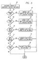
- FIG. 5 is a flow diagram illustrating steps performed by the Selective Deposition Modeling system controls 48 to enable manipulation of a job.
- the Selective Deposition Modeling system controls 48 receive a request to manipulate a job in a job queue. If the request is to promote a job, as represented by Block 62, the Selective Deposition Modeling system controls 48 move the job ahead in the queue to a specified position, as represented by Block 64. If the request is to demote a job, as represented by Block 66, the Selective Deposition Modeling system controls 48 move the job back in the queue to a specified position, as represented by Block 68.
- the Selective Deposition Modeling system controls 48 move the job to the front of the queue, as represented by Block 72. If the request is to move a job to the "bottom", as represented by Block 74, the Selective Deposition Modeling system controls 48 move the job to the rear of the queue, as represented by Block 76. If the request is to delete a job, as represented by Block 78, the Selective Deposition Modeling system controls 48 delete the job from the queue, as represented by Block 80.
- the Selective Deposition Modeling system controls 48 automatically combine multiple jobs in a job queue into one build process. That is, the objects corresponding to the combined jobs are built at the same time on the build platform.
- the Selective Deposition Modeling system controls 48 stores jobs at the "bottom" of a job queue.
- the Selective Deposition Modeling system controls 48 may process the jobs in the order that they are received or some other order. Near the completion of building a job, the Selective Deposition Modeling system controls 48 look at the job queue to determine which job or jobs to process next. Typically, the Selective Deposition Modeling system controls 48 will prepare a job to be built while another job is being completed.
- the Selective Deposition Modeling system controls 48 will search the job queue to identify jobs that can be combined and built at the same time.
- the jobs that can be combined must all completely fit on the build platform. Additionally, in one embodiment, overlap in a direction (e.g., the Z-dimension) may be tolerated, if, for example, the objects can be separated by supports. The combination of jobs becomes the next build process.
- a user can submit a job from a client computer with an indication (e.g., flag or condition) that the job is not to be combined. A user may do this so that, for example, a short object of theirs is not combined with a large object, which would delay completion of the building of the short object. If the Selective Deposition Modeling system controls 48 encounter a job with such an indication, the Selective Deposition Modeling system controls do not combine that job with any other. Second, if the job queue only contains one job, the Selective Deposition Modeling system controls 48 process that job without attempting to combine the job.
- an indication e.g., flag or condition
- the Selective Deposition Modeling system controls 48 could defer processing the single job in the job queue and wait for other jobs to be entered into the job queue to attempt to combine jobs. Third, if the build platform is full (with one large job or a group of jobs that have been combined already), the Selective Deposition Modeling system controls 48 do not attempt to combine that large job or group of jobs with any other jobs pending in the job queue.
- the first job in the job queue is selected, and then the job queue is searched for jobs that can be combined with the selected job.
- the best set of objects corresponding to jobs in the job queue are combined, without regard to their position in the job queue (i.e., first, second, etc.).
- a common attribute may be used to combine jobs. For example, the height of objects for the jobs may be used to select jobs to be combined (e.g., all short objects are combined into one build process). If just short objects were selected for combination all of the time, there is a possibility that a tall object may never be selected to be built.
- an alternative embodiment is to select jobs in increasing order of the characteristic, such as height (e.g., first select jobs of height 1 inch or less, then select jobs of height 1.25 inches or less, etc.).
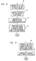
- FIG. 6 is a flow diagram illustrating steps performed by the Selective Deposition Modeling system controls 48 to enable combining multiple jobs to generate a single build.
- the Selective Deposition Modeling system controls 48 search the job queue to identify jobs to be combined into one build based on one or more pre-determined factors, as represented by Block 90. Then, the Selective Deposition Modeling system controls 48 combine the identified jobs to create a single build.
Landscapes
- Chemical & Material Sciences (AREA)
- Engineering & Computer Science (AREA)
- Materials Engineering (AREA)
- Manufacturing & Machinery (AREA)
- Physics & Mathematics (AREA)
- Mechanical Engineering (AREA)
- Optics & Photonics (AREA)
- Laser Beam Processing (AREA)
Claims (45)
- Ein Rapid-Prototyping-System, aufweisend:Mittel zum Annehmen von mehreren Aufträgen, die in einer Auftragswarteschlange angeordnet werden sollen, wobei jeder Auftrag eine Anfrage zum Aufbauen eines dreidimensionalen Objektes durch zumindest ein Rapid-Prototyping-Gerät umfasst; undMittel zum Kombinieren von zwei oder mehreren Aufträgen in einem von dem Rapid-Prototyping-Gerät durchgeführten Aufbauprozess.
- Das System gemäß Anspruch 1, in dem die Auftragswarteschlange sich bei dem Rapid-Prototyping-Gerät befindet.
- Das System gemäß Anspruch 1 oder Anspruch 2, umfassend Mittel zum Identifizieren von zu kombinierenden Aufträgen in der Auftragswarteschlange.
- Das System gemäß einem der vorherigen Ansprüche, umfassend Mittel zum Identifizieren, dass ein Auftrag als nicht kombinierbar gekennzeichnet ist.
- Das System gemäß einem der vorherigen Ansprüche, umfassend Mittel zum Identifizieren, dass eine bestimmte Kombination von Aufträgen zu Objekten führen würde, die überlappenden Aufträgen entsprechen.
- Das System gemäß einem der vorherigen Ansprüche, umfassend Mittel zum Identifizieren, dass eine Kombination von Aufträgen eine Aufbauplattform füllt.
- Das System gemäß einem der vorherigen Ansprüche, wobei die Mittel zum Kombinieren der Aufträge für eine Maximierung einer Y-Dimension oder einer Z-Dimension bereitgestellt werden.
- Das System gemäß einem der vorherigen Ansprüche, umfassend ein Mittel zum Manipulieren der Aufträge in der Auftragswarteschlange.
- Das System gemäß Anspruch 8, wobei das Mittel zum Manipulieren Mittel zum Höherstufen eines Auftrags in der Auftragswarteschlange umfasst.
- Das System gemäß Anspruch 8, wobei das Mittel zum Manipulieren Mittel zum Zurückstufen eines Auftrags in der Auftragswarteschlange umfasst.
- Das System gemäß Anspruch 8, wobei das Mittel zum Manipulieren Mittel zum Bewegen eines Auftrags zu einer Spitze der Auftragswarteschlange umfasst.
- Das System gemäß Anspruch 8, wobei das Mittel zum Manipulieren Mittel zum Bewegen eines Auftrags an ein Ende der Auftragswarteschlange umfasst.
- Das System gemäß Anspruch 8, wobei das Mittel zum Manipulieren Mittel zum Löschen eines Auftrags in der Auftragswarteschlange umfasst.
- Das System gemäß Anspruch 8, wobei das Mittel zum Manipulieren Mittel zum Empfangen eines Befehls von einem Client-Computer umfasst, um einen Auftrag in der Auftragswarteschlange zu manipulieren.
- Das System gemäß einem der vorherigen Ansprüche, umfassend zumindest einen Client-Computer zur Kommunikation mit dem Rapid-Prototyping-System, in dem das Mittel zum Akzeptieren mehrerer Aufträge bereitgestellt ist, um Aufträge von dem Client-Computer zu empfangen, um ein oder mehrere dreidimensionale Objekte zu erzeugen.
- Das System gemäß Anspruch 15, in dem der zumindest eine Client-Computer direkt mit dem Rapid-Prototyping-Gerät verbunden ist.
- Das System gemäß einem der vorherigen Aruprüche, wobei das Rapid-Prototyping-System ein System zur selektiven Ablagerungsmodslierung, ein Stereolithographiegerät, ein Gerät zur Herstellung laminierter Objekte oder ein Laser-Sinter-Gerät ist.
- Das System gemäß einem der vorherigen Ansprüche, umfassend Mittel zum Anzeigen einer Vorschau eines dreidimensionalen Objekts in dreidimensionaler Form, welches einem Auftrag in der Auftragswarteschlange entspricht.
- Das System gemäß Anspruch 18 aufweisend:Mittel zum Bereitstellen einer Liste von Aufträgen an einen Client-Computer; undMittel zum Empfangen einer Auswahl eines Auftrags von dem Client-Computer, die als Vorschau angezeigt werden soll.
- Das System gemäß Anspruch 18 oder Anspruch 19 umfassend:Mittel zum Bereitstellen von Darstellungen an einen Client-Computer, die den Aufträgen in der Auftragswarteschlange zugeordnet sind; undMittel zum Empfangen einer Auswahl einer Darstellung von dem Client-Computer, die als Vorschau angezeigt werden soll.
- Das System gemäß einem der Ansprüche 18 bis 20, umfassend Mittel zum Übertragen von Daten an einen Client-Computer zum Rendem bzw. grafischen Aufbauen des dreidimensionalen Objekts in dreidimensionaler Form auf dem Client-Computer.
- Das System gemäß Anspruch 21, umfassend Mittel zum simultanen Rendem mehrerer Objekte in dreidimensionaler Form auf dem Client-Computer.
- Das System gemäß Anspruch 22, wobei jedes der mehreren Objekte einem anderen Auftrag entspricht.
- Ein Verfahren zum Erzeugen eines dreidimensionalen Objekts in einem Rapid-Prototyping-System, wobei das Verfahren die folgenden Schritte aufweist:Annehmen mehrerer Aufträge, die in einer Außragswarteschlange angeordnet werden sollen, wobei jeder Auftrag eine Anfrage zum Aufbauen eines dreidimensionalen Objektes durch zumindest ein Rapid-Prototyping-Gerät umfasst; undManipulieren der Aufträge, um zwei oder mehrere Aufträge in einem Aufbauprozess zu kombinieren, der durch das Rapid-Prototyping-Gerät durchgeführt wird.
- Das Verfahren gemäß Anspruch 24, umfassen ein Identifizieren von Aufträgen, die kombiniert werden sollen, in der Auftragswarteschlange.
- Das Verfahren gemäß Anspruch 24 oder Anspruch 25 umfassend ein Identifizieren, dass ein Auftrag als nicht kombinierbar gekennzeichnet ist.
- Das Verfahren gemäß einem der Ansprüche 24 bis 26, umfassend ein Identifizieren, dass eine bestimmte Kombination von Aufträgen zu Objekten führen würde, die überlappenden Aufträgen entsprechen.
- Das Verfahren gemäß einem der Ansprüche 24 bis 27, umfassend ein Identifizieren, dass eine Kombination von Aufträgen eine Aufbauplattform füllt.
- Das Verfahren gemäß einem der Ansprüche 24 bis 28, in dem die Aufträge kombiniert werden, indem eine Z-Dimension oder eine Y-Dimension maximiert wird.
- Das Verfahren gemäß einem der Ansprüche 24 bis 29, umfassend ein Höherstufen eines Auftrags in der Auftragswarteschlange.
- Das Verfahren gemäß Anspruch 30, umfassend ein Bewegen eines Auftrags zu einer Spitze der Auftragswarteschlange.
- Das Verfahren gemäß einem der Ansprüche 24 bis 31, umfassend ein Zurückstufen eines Auftrags in der Auftragswarteschlange.
- Das Verfahren gemäß Anspruch 32, umfassend ein Bewegen eines Auftrags zu einem Ende der Auftragswarteschlange.
- Das Verfahren gemäß einem der Ansprüche 24 bis 33, umfassend ein Löschen eines Auftrags in der Auftragswarteschlange.
- Das Verfahren gemäß einem der Ansprüche 24 bis 34, umfassen ein Empfangen eines Befehls von einem Client-Computer, um einen Auftrag in der Auftragswarteschlange zu manipulieren.
- Das Verfahren gemäß einem der Ansprüche 24 bis 35, umfassend:Verbinden zumindest eines Client-Computers mit dem Rapid-Prototyping-Gerät; undEmpfangen von Befehlen von dem zumindest einem Client-Computer auf dem Rapid-Prototyping-Gerät.
- Das Verfahren gemäß Anspruch 36, in dem zumindest ein Client-Computer direkt mit dem Rapid-Prototyping-Gerät verbunden ist.
- Das Verfahren gemäß einem der Ansprüche 24 bis 37, wobei das Rapid-Prototyping-System ein System zur selektiven Ablagerungsmodulierung, ein Stereolithographie-Gerät, ein Gerät zur Herstellung laminierter Objekte oder ein Laser-Sinter-Gerät ist.
- Das Verfahren gemäß einem der Ansprüche 24 bis 38, umfassend ein Anzeigen einer Vorschau eines dreidimensionalen Objektes in dreidimensionaler Form, die einem Auftrag in der Auftragswarteschlange entspricht.
- Das Verfahren gemäß Anspruch 39, umfassend:Bereitstellen einer Liste von Aufträgen an einen Client-Computer; undEmpfangen einer Auswahl eines Auftrags von dem Client-Computer, die als Vorschau angezeigt werden soll.
- Das Verfahren gemäß Anspruch 39, umfassend:Bereitstellen von Darstellungen in einem Client-Computer, die den Aufträgen in der Auftragswarteschlange zugeordnet sind; undEmpfangen einer Auswahl einer Darstellung von dem Client-Computer, die als Vorschau angezeigt werden soll.
- Das Verfahren gemäß einem der Ansprüche 39 bis 41, weiterhin aufweisend den Schritt des Übertragens von Daten an einen Client-Computer, um das dreidimensionale Objekt auf dem Client-Computer in dreidimensional Form zu Rendern bzw. grafisch aufzubauen.
- Das Verfahren gemäß Anspruch 42 weiterhin aufweisend den Schritt des simultanen Renderns mehrerer Objekte in dreidimensionaler Form auf dem Client-Computer.
- Das Verfahren gemäß Anspruch 43, wobei jedes der mehreren Objekte einem anderen Auftrag entspricht.
- Ein Computerprogranunprodukt zum Erzeugen eines dreidimensionalen Objekts in einem Rapid-Prototyping-System, wobei das Computerprogramm Anweisungen umfasst, die durch einen Computer ausführbar sind, um die folgenden Schritte durchzuführen;Akzeptieren mehrerer Aufträge, die in einer Auftragswarteschlange angeordnet werden sollen, wobei jeder Auftrag eine Anfrage zum Aufbauen eines dreidimensionalen Objektes durch zumindest ein Rapid-Prototyping-Gerät umfasst; undManipulieren der Aufträge, um zwei oder mehrere Aufträge in einen Aufbauprozess zu kombinieren, der durch das Rapid-Prototyping-Gerät durchgeführt wird.
Applications Claiming Priority (2)
| Application Number | Priority Date | Filing Date | Title |
|---|---|---|---|
| US257357 | 1999-02-25 | ||
| US09/257,357 US6490496B1 (en) | 1999-02-25 | 1999-02-25 | Method, apparatus, and article of manufacture for a control system in a selective deposition modeling system |
Publications (3)
| Publication Number | Publication Date |
|---|---|
| EP1031392A2 EP1031392A2 (de) | 2000-08-30 |
| EP1031392A3 EP1031392A3 (de) | 2001-12-19 |
| EP1031392B1 true EP1031392B1 (de) | 2004-05-26 |
Family
ID=22975985
Family Applications (1)
| Application Number | Title | Priority Date | Filing Date |
|---|---|---|---|
| EP00301433A Expired - Lifetime EP1031392B1 (de) | 1999-02-25 | 2000-02-23 | Herstellungsverfahren und -Vorrichtung für ein Steuerungssystem in einem selektiv ablagernden Modellierungssystem |
Country Status (5)
| Country | Link |
|---|---|
| US (1) | US6490496B1 (de) |
| EP (1) | EP1031392B1 (de) |
| JP (1) | JP4339484B2 (de) |
| AT (1) | ATE267656T1 (de) |
| DE (1) | DE60010943T2 (de) |
Cited By (3)
| Publication number | Priority date | Publication date | Assignee | Title |
|---|---|---|---|---|
| EP2065772A2 (de) | 2007-11-30 | 2009-06-03 | FIT Fruth Innovative Technologien GmbH | Verfahren und Fertigungssysteme zum Herstellen von Bauteilen unter Ausnutzung von geometrischen Freiräumen auf Fertigungsanlagen |
| CN107263853A (zh) * | 2016-03-30 | 2017-10-20 | 佳能株式会社 | 形成控制装置及其方法 |
| CN109834927A (zh) * | 2017-11-29 | 2019-06-04 | Cl产权管理有限公司 | 用于操作至少一个用于制造三维物体的设备的方法 |
Families Citing this family (55)
| Publication number | Priority date | Publication date | Assignee | Title |
|---|---|---|---|---|
| US7010472B1 (en) | 1997-05-12 | 2006-03-07 | Mcdonnell Douglas Corporation | Knowledge driven composite design optimization process and system therefor |
| US6658314B1 (en) * | 1999-10-06 | 2003-12-02 | Objet Geometries Ltd. | System and method for three dimensional model printing |
| US20050104241A1 (en) * | 2000-01-18 | 2005-05-19 | Objet Geometried Ltd. | Apparatus and method for three dimensional model printing |
| US6850334B1 (en) | 2000-01-18 | 2005-02-01 | Objet Geometries Ltd | System and method for three dimensional model printing |
| US20030207959A1 (en) * | 2000-03-13 | 2003-11-06 | Eduardo Napadensky | Compositions and methods for use in three dimensional model printing |
| US7300619B2 (en) * | 2000-03-13 | 2007-11-27 | Objet Geometries Ltd. | Compositions and methods for use in three dimensional model printing |
| US8481241B2 (en) | 2000-03-13 | 2013-07-09 | Stratasys Ltd. | Compositions and methods for use in three dimensional model printing |
| US6799081B1 (en) * | 2000-11-15 | 2004-09-28 | Mcdonnell Douglas Corporation | Fiber placement and fiber steering systems and corresponding software for composite structures |
| US20020147521A1 (en) * | 2001-03-14 | 2002-10-10 | Milling Systems And Concepts Pte Ltd. | Prototype production system and method |
| US20020171177A1 (en) * | 2001-03-21 | 2002-11-21 | Kritchman Elisha M. | System and method for printing and supporting three dimensional objects |
| CA2448736C (en) | 2001-06-05 | 2010-08-10 | Mikro Systems, Inc. | Methods for manufacturing three-dimensional devices and devices created thereby |
| US7141812B2 (en) | 2002-06-05 | 2006-11-28 | Mikro Systems, Inc. | Devices, methods, and systems involving castings |
| US7785098B1 (en) | 2001-06-05 | 2010-08-31 | Mikro Systems, Inc. | Systems for large area micro mechanical systems |
| US6863859B2 (en) * | 2001-08-16 | 2005-03-08 | Objet Geometries Ltd. | Reverse thermal gels and the use thereof for rapid prototyping |
| US6841589B2 (en) * | 2001-10-03 | 2005-01-11 | 3D Systems, Inc. | Ultra-violet light curable hot melt composition |
| US20030151167A1 (en) | 2002-01-03 | 2003-08-14 | Kritchman Eliahu M. | Device, system and method for accurate printing of three dimensional objects |
| WO2004024447A2 (en) * | 2002-09-12 | 2004-03-25 | Objet Geometries Ltd. | Device, system and method for calibration in three-dimensional model printing |
| US7725209B2 (en) * | 2002-11-12 | 2010-05-25 | Objet Geometries Ltd | Three-dimensional object printing |
| WO2004050323A1 (en) | 2002-12-03 | 2004-06-17 | Objet Geometries Ltd. | Process of and apparatus for three-dimensional printing |
| AU2003900180A0 (en) * | 2003-01-16 | 2003-01-30 | Silverbrook Research Pty Ltd | Method and apparatus (dam001) |
| US7104773B2 (en) | 2003-03-07 | 2006-09-12 | Ricoh Printing Systems, Ltd. | Three-dimensional laminating molding device |
| EP3527351B1 (de) | 2003-05-01 | 2020-10-07 | Stratasys Ltd. | Vorrichtung zur herstellung eines gegenstands durch nacheinander auftragen von schichten aus konstruktionsmaterial |
| WO2004096527A2 (en) | 2003-05-01 | 2004-11-11 | Objet Geometries Ltd. | Rapid prototyping apparatus |
| US7422713B2 (en) | 2003-10-14 | 2008-09-09 | Hewlett-Packard Development Company, L.P. | Hybrid organic-inorganic composition for solid freeform fabrication |
| US7243055B2 (en) * | 2004-01-28 | 2007-07-10 | The Boeing Company | Composite stacking sequence optimization for multi-zoned composites |
| US7094117B2 (en) * | 2004-02-27 | 2006-08-22 | Micron Technology, Inc. | Electrical contacts with dielectric cores |
| US8014889B2 (en) * | 2005-10-13 | 2011-09-06 | Stratasys, Inc. | Transactional method for building three-dimensional objects |
| US7555357B2 (en) * | 2006-01-31 | 2009-06-30 | Stratasys, Inc. | Method for building three-dimensional objects with extrusion-based layered deposition systems |
| US7403833B2 (en) * | 2006-04-03 | 2008-07-22 | Stratasys, Inc. | Method for optimizing spatial orientations of computer-aided design models |
| DE102006019963B4 (de) * | 2006-04-28 | 2023-12-07 | Envisiontec Gmbh | Vorrichtung und Verfahren zur Herstellung eines dreidimensionalen Objekts durch schichtweises Verfestigen eines unter Einwirkung von elektromagnetischer Strahlung verfestigbaren Materials mittels Maskenbelichtung |
| CN101484949B (zh) * | 2006-07-07 | 2013-08-21 | 皇家飞利浦电子股份有限公司 | 用于选择性透射电磁辐射的滤线栅 |
| US7636610B2 (en) * | 2006-07-19 | 2009-12-22 | Envisiontec Gmbh | Method and device for producing a three-dimensional object, and computer and data carrier useful therefor |
| US8765045B2 (en) * | 2007-01-12 | 2014-07-01 | Stratasys, Inc. | Surface-treatment method for rapid-manufactured three-dimensional objects |
| US20080309665A1 (en) * | 2007-06-13 | 2008-12-18 | 3D Systems, Inc., A California Corporation | Distributed rapid prototyping |
| US7744364B2 (en) | 2007-06-21 | 2010-06-29 | Stratasys, Inc. | Extrusion tip cleaning assembly |
| US8050786B2 (en) * | 2007-07-11 | 2011-11-01 | Stratasys, Inc. | Method for building three-dimensional objects with thin wall regions |
| US8075300B2 (en) * | 2008-06-30 | 2011-12-13 | Stratasys, Inc. | Vapor smoothing surface finishing system |
| JP5096265B2 (ja) * | 2008-08-29 | 2012-12-12 | 長野日本無線株式会社 | 三次元造形機 |
| JP5108685B2 (ja) * | 2008-08-29 | 2012-12-26 | 長野日本無線株式会社 | 三次元造形機 |
| US9315663B2 (en) | 2008-09-26 | 2016-04-19 | Mikro Systems, Inc. | Systems, devices, and/or methods for manufacturing castings |
| US8222908B2 (en) | 2010-02-16 | 2012-07-17 | Stratasys, Inc. | Capacitive detector for use in extrusion-based digital manufacturing systems |
| US8752054B2 (en) * | 2010-03-11 | 2014-06-10 | Avaya Inc. | Intelligent merging of transactions based on a variety of criteria |
| US20120092724A1 (en) * | 2010-08-18 | 2012-04-19 | Pettis Nathaniel B | Networked three-dimensional printing |
| US8414280B2 (en) | 2010-08-18 | 2013-04-09 | Makerbot Industries, Llc | Networked three-dimensional printing |
| US8984519B2 (en) * | 2010-11-17 | 2015-03-17 | Nec Laboratories America, Inc. | Scheduler and resource manager for coprocessor-based heterogeneous clusters |
| US8813824B2 (en) | 2011-12-06 | 2014-08-26 | Mikro Systems, Inc. | Systems, devices, and/or methods for producing holes |
| JP2015168135A (ja) * | 2014-03-06 | 2015-09-28 | 三井化学株式会社 | 三次元物体の製造装置および三次元物体の製造方法 |
| JP6456033B2 (ja) * | 2014-03-31 | 2019-01-23 | 株式会社Fuji | 造形装置 |
| WO2016053263A1 (en) | 2014-09-30 | 2016-04-07 | Hewlett-Packard Development Company, L.P. | Virtual build beds |
| US9889608B2 (en) | 2014-11-10 | 2018-02-13 | International Business Machines Corporation | Matching the scale of independent objects or intelligently scaling objects when 3D printing |
| JP6839528B2 (ja) * | 2016-11-30 | 2021-03-10 | 株式会社ミマキエンジニアリング | 印刷制御プログラム、印刷制御装置および印刷制御方法 |
| US10691449B2 (en) * | 2017-04-27 | 2020-06-23 | Microsoft Technology Licensing, Llc | Intelligent automatic merging of source control queue items |
| JP7358225B2 (ja) * | 2019-12-17 | 2023-10-10 | 三菱重工業株式会社 | 3次元造形用支持装置及び3次元造形物の製造方法 |
| US11645200B2 (en) * | 2020-11-24 | 2023-05-09 | International Business Machines Corporation | Reducing load balancing work stealing |
| US12417262B2 (en) * | 2022-09-20 | 2025-09-16 | Dish Network L.L.C. | Systems and methods for 3D printing of limited edition virtual items |
Family Cites Families (14)
| Publication number | Priority date | Publication date | Assignee | Title |
|---|---|---|---|---|
| US4896269A (en) * | 1988-02-29 | 1990-01-23 | General Electric Company | Job shop scheduling and production method and apparatus |
| US5197140A (en) * | 1989-11-17 | 1993-03-23 | Texas Instruments Incorporated | Sliced addressing multi-processor and method of operation |
| US6175422B1 (en) * | 1991-01-31 | 2001-01-16 | Texas Instruments Incorporated | Method and apparatus for the computer-controlled manufacture of three-dimensional objects from computer data |
| US5402350A (en) * | 1991-06-28 | 1995-03-28 | Texas Instruments Incorporated | Scheduling for multi-task manufacturing equipment |
| JP3215881B2 (ja) * | 1994-05-27 | 2001-10-09 | イーオーエス ゲゼルシャフト ミット ベシュレンクテル ハフツング イレクトロ オプティカル システムズ | 鋳込み技術に使用される方法 |
| US5592654A (en) * | 1994-06-03 | 1997-01-07 | Integrated Device Technology, Inc. | Apparatus and method for converting a job conforming to a first protocol into a job conforming to a second protocol |
| GB9414951D0 (en) * | 1994-07-25 | 1994-09-14 | British Telecomm | Computer system having client-server architecture |
| US5943235A (en) * | 1995-09-27 | 1999-08-24 | 3D Systems, Inc. | Rapid prototyping system and method with support region data processing |
| JP2940450B2 (ja) * | 1995-10-26 | 1999-08-25 | 日本電気株式会社 | クラスタ型コンピュータのジョブスケジュール方法及び装置 |
| US5764521A (en) | 1995-11-13 | 1998-06-09 | Stratasys Inc. | Method and apparatus for solid prototyping |
| US5786023A (en) * | 1996-02-13 | 1998-07-28 | Maxwell; James L. | Method and apparatus for the freeform growth of three-dimensional structures using pressurized precursor flows and growth rate control |
| US6021358A (en) * | 1996-09-18 | 2000-02-01 | Sachs; George A. | Three dimensional model and mold making method using thick-slice subtractive fabrication |
| US5936861A (en) * | 1997-08-15 | 1999-08-10 | Nanotek Instruments, Inc. | Apparatus and process for producing fiber reinforced composite objects |
| US6162378A (en) * | 1999-02-25 | 2000-12-19 | 3D Systems, Inc. | Method and apparatus for variably controlling the temperature in a selective deposition modeling environment |
-
1999
- 1999-02-25 US US09/257,357 patent/US6490496B1/en not_active Expired - Lifetime
-
2000
- 2000-02-23 DE DE60010943T patent/DE60010943T2/de not_active Expired - Lifetime
- 2000-02-23 AT AT00301433T patent/ATE267656T1/de not_active IP Right Cessation
- 2000-02-23 EP EP00301433A patent/EP1031392B1/de not_active Expired - Lifetime
- 2000-02-25 JP JP2000049737A patent/JP4339484B2/ja not_active Expired - Lifetime
Cited By (5)
| Publication number | Priority date | Publication date | Assignee | Title |
|---|---|---|---|---|
| EP2065772A2 (de) | 2007-11-30 | 2009-06-03 | FIT Fruth Innovative Technologien GmbH | Verfahren und Fertigungssysteme zum Herstellen von Bauteilen unter Ausnutzung von geometrischen Freiräumen auf Fertigungsanlagen |
| EP2065772A3 (de) * | 2007-11-30 | 2011-03-16 | FIT Fruth Innovative Technologien GmbH | Verfahren und Fertigungssysteme zum Herstellen von Bauteilen unter Ausnutzung von geometrischen Freiräumen auf Fertigungsanlagen |
| CN107263853A (zh) * | 2016-03-30 | 2017-10-20 | 佳能株式会社 | 形成控制装置及其方法 |
| CN109834927A (zh) * | 2017-11-29 | 2019-06-04 | Cl产权管理有限公司 | 用于操作至少一个用于制造三维物体的设备的方法 |
| CN109834927B (zh) * | 2017-11-29 | 2022-04-26 | Cl产权管理有限公司 | 用于操作至少一个用于制造三维物体的设备的方法 |
Also Published As
| Publication number | Publication date |
|---|---|
| US6490496B1 (en) | 2002-12-03 |
| DE60010943D1 (de) | 2004-07-01 |
| EP1031392A3 (de) | 2001-12-19 |
| ATE267656T1 (de) | 2004-06-15 |
| DE60010943T2 (de) | 2005-06-23 |
| JP2001058357A (ja) | 2001-03-06 |
| EP1031392A2 (de) | 2000-08-30 |
| JP4339484B2 (ja) | 2009-10-07 |
Similar Documents
| Publication | Publication Date | Title |
|---|---|---|
| EP1031392B1 (de) | Herstellungsverfahren und -Vorrichtung für ein Steuerungssystem in einem selektiv ablagernden Modellierungssystem | |
| US6136252A (en) | Apparatus for electro-chemical deposition with thermal anneal chamber | |
| US6162378A (en) | Method and apparatus for variably controlling the temperature in a selective deposition modeling environment | |
| US6347257B1 (en) | Method and apparatus for controlling the drop volume in a selective deposition modeling environment | |
| DE69625220T2 (de) | Verfahren und vorrichtung zur datenverarbeiten und zur system-steuerung in einem selectiven ablagerungsmodellsystem | |
| US7077638B2 (en) | Selective deposition modeling method and apparatus for forming three-dimensional objects and supports | |
| US6572807B1 (en) | Method of improving surfaces in selective deposition modeling | |
| US7290221B2 (en) | User interface, method and apparatus for providing three-dimensional object fabrication status | |
| US6357855B1 (en) | Non-linear printhead assembly | |
| US20120133080A1 (en) | Additive Manufacturing Methods for Improved Curl Control and Sidewall Quality | |
| EP3856492B1 (de) | Verfahren und system zur additiven herstellung mit einer opferstruktur zur einfachen entfernung | |
| US12358226B2 (en) | Service station for a three-dimensional printing system | |
| CN109072600A (zh) | 3d打印 | |
| EP3906149B1 (de) | Verfahren und system zur steuerung eines kühlsystems im dreidimensionalen druck | |
| CN1530230A (zh) | 用于控制固体自由成形制造中印刷头温度的方法和系统 | |
| JP2026035658A (ja) | 三次元印刷用レベリング装置 | |
| EP4143008B1 (de) | Dreidimensionales drucksystem umfassend system zur verbesserung der sicherheit im dreidimensionalen drucken und entsprechendes verfahren | |
| CN209240487U (zh) | 一种3d打印组件及3d打印设备 | |
| EP4642616A1 (de) | Abfallbeseitigung für dreidimensionales drucken |
Legal Events
| Date | Code | Title | Description |
|---|---|---|---|
| PUAI | Public reference made under article 153(3) epc to a published international application that has entered the european phase |
Free format text: ORIGINAL CODE: 0009012 |
|
| AK | Designated contracting states |
Kind code of ref document: A2 Designated state(s): AT BE CH CY DE DK ES FI FR GB GR IE IT LI LU MC NL PT SE |
|
| AX | Request for extension of the european patent |
Free format text: AL;LT;LV;MK;RO;SI |
|
| PUAL | Search report despatched |
Free format text: ORIGINAL CODE: 0009013 |
|
| AK | Designated contracting states |
Kind code of ref document: A3 Designated state(s): AT BE CH CY DE DK ES FI FR GB GR IE IT LI LU MC NL PT SE |
|
| AX | Request for extension of the european patent |
Free format text: AL;LT;LV;MK;RO;SI |
|
| RIC1 | Information provided on ipc code assigned before grant |
Free format text: 7B 22F 3/10 A, 7B 29C 67/00 B, 7G 05B 19/4099 B |
|
| 17P | Request for examination filed |
Effective date: 20020506 |
|
| 17Q | First examination report despatched |
Effective date: 20020716 |
|
| AKX | Designation fees paid |
Free format text: AT BE CH CY DE DK ES FI FR GB GR IE IT LI LU MC NL PT SE |
|
| RTI1 | Title (correction) |
Free format text: METHOD AND APPARATUS OF MANUFACTURE FOR A CONTROL SYSTEM IN A SELECTIVE DEPOSITION MODELING SYSTEM |
|
| GRAP | Despatch of communication of intention to grant a patent |
Free format text: ORIGINAL CODE: EPIDOSNIGR1 |
|
| GRAS | Grant fee paid |
Free format text: ORIGINAL CODE: EPIDOSNIGR3 |
|
| GRAA | (expected) grant |
Free format text: ORIGINAL CODE: 0009210 |
|
| AK | Designated contracting states |
Kind code of ref document: B1 Designated state(s): AT BE CH CY DE DK ES FI FR GB GR IE IT LI LU MC NL PT SE |
|
| PG25 | Lapsed in a contracting state [announced via postgrant information from national office to epo] |
Ref country code: IT Free format text: LAPSE BECAUSE OF FAILURE TO SUBMIT A TRANSLATION OF THE DESCRIPTION OR TO PAY THE FEE WITHIN THE PRESCRIBED TIME-LIMIT;WARNING: LAPSES OF ITALIAN PATENTS WITH EFFECTIVE DATE BEFORE 2007 MAY HAVE OCCURRED AT ANY TIME BEFORE 2007. THE CORRECT EFFECTIVE DATE MAY BE DIFFERENT FROM THE ONE RECORDED. Effective date: 20040526 Ref country code: LI Free format text: LAPSE BECAUSE OF FAILURE TO SUBMIT A TRANSLATION OF THE DESCRIPTION OR TO PAY THE FEE WITHIN THE PRESCRIBED TIME-LIMIT Effective date: 20040526 Ref country code: AT Free format text: LAPSE BECAUSE OF FAILURE TO SUBMIT A TRANSLATION OF THE DESCRIPTION OR TO PAY THE FEE WITHIN THE PRESCRIBED TIME-LIMIT Effective date: 20040526 Ref country code: CH Free format text: LAPSE BECAUSE OF FAILURE TO SUBMIT A TRANSLATION OF THE DESCRIPTION OR TO PAY THE FEE WITHIN THE PRESCRIBED TIME-LIMIT Effective date: 20040526 Ref country code: FI Free format text: LAPSE BECAUSE OF FAILURE TO SUBMIT A TRANSLATION OF THE DESCRIPTION OR TO PAY THE FEE WITHIN THE PRESCRIBED TIME-LIMIT Effective date: 20040526 Ref country code: BE Free format text: LAPSE BECAUSE OF FAILURE TO SUBMIT A TRANSLATION OF THE DESCRIPTION OR TO PAY THE FEE WITHIN THE PRESCRIBED TIME-LIMIT Effective date: 20040526 |
|
| REG | Reference to a national code |
Ref country code: GB Ref legal event code: FG4D |
|
| REG | Reference to a national code |
Ref country code: CH Ref legal event code: EP |
|
| REG | Reference to a national code |
Ref country code: IE Ref legal event code: FG4D |
|
| REF | Corresponds to: |
Ref document number: 60010943 Country of ref document: DE Date of ref document: 20040701 Kind code of ref document: P |
|
| PG25 | Lapsed in a contracting state [announced via postgrant information from national office to epo] |
Ref country code: SE Free format text: LAPSE BECAUSE OF FAILURE TO SUBMIT A TRANSLATION OF THE DESCRIPTION OR TO PAY THE FEE WITHIN THE PRESCRIBED TIME-LIMIT Effective date: 20040826 Ref country code: DK Free format text: LAPSE BECAUSE OF FAILURE TO SUBMIT A TRANSLATION OF THE DESCRIPTION OR TO PAY THE FEE WITHIN THE PRESCRIBED TIME-LIMIT Effective date: 20040826 Ref country code: GR Free format text: LAPSE BECAUSE OF FAILURE TO SUBMIT A TRANSLATION OF THE DESCRIPTION OR TO PAY THE FEE WITHIN THE PRESCRIBED TIME-LIMIT Effective date: 20040826 |
|
| PG25 | Lapsed in a contracting state [announced via postgrant information from national office to epo] |
Ref country code: ES Free format text: LAPSE BECAUSE OF FAILURE TO SUBMIT A TRANSLATION OF THE DESCRIPTION OR TO PAY THE FEE WITHIN THE PRESCRIBED TIME-LIMIT Effective date: 20040906 |
|
| REG | Reference to a national code |
Ref country code: CH Ref legal event code: PL |
|
| ET | Fr: translation filed | ||
| PG25 | Lapsed in a contracting state [announced via postgrant information from national office to epo] |
Ref country code: IE Free format text: LAPSE BECAUSE OF NON-PAYMENT OF DUE FEES Effective date: 20050223 Ref country code: CY Free format text: LAPSE BECAUSE OF FAILURE TO SUBMIT A TRANSLATION OF THE DESCRIPTION OR TO PAY THE FEE WITHIN THE PRESCRIBED TIME-LIMIT Effective date: 20050223 Ref country code: LU Free format text: LAPSE BECAUSE OF NON-PAYMENT OF DUE FEES Effective date: 20050223 |
|
| PG25 | Lapsed in a contracting state [announced via postgrant information from national office to epo] |
Ref country code: MC Free format text: LAPSE BECAUSE OF NON-PAYMENT OF DUE FEES Effective date: 20050228 |
|
| PLBE | No opposition filed within time limit |
Free format text: ORIGINAL CODE: 0009261 |
|
| STAA | Information on the status of an ep patent application or granted ep patent |
Free format text: STATUS: NO OPPOSITION FILED WITHIN TIME LIMIT |
|
| 26N | No opposition filed |
Effective date: 20050301 |
|
| REG | Reference to a national code |
Ref country code: IE Ref legal event code: MM4A |
|
| PG25 | Lapsed in a contracting state [announced via postgrant information from national office to epo] |
Ref country code: PT Free format text: LAPSE BECAUSE OF NON-PAYMENT OF DUE FEES Effective date: 20041026 |
|
| REG | Reference to a national code |
Ref country code: FR Ref legal event code: PLFP Year of fee payment: 17 |
|
| REG | Reference to a national code |
Ref country code: FR Ref legal event code: PLFP Year of fee payment: 18 |
|
| REG | Reference to a national code |
Ref country code: FR Ref legal event code: PLFP Year of fee payment: 19 |
|
| PGFP | Annual fee paid to national office [announced via postgrant information from national office to epo] |
Ref country code: NL Payment date: 20190226 Year of fee payment: 20 |
|
| PGFP | Annual fee paid to national office [announced via postgrant information from national office to epo] |
Ref country code: GB Payment date: 20190227 Year of fee payment: 20 Ref country code: DE Payment date: 20190227 Year of fee payment: 20 |
|
| PGFP | Annual fee paid to national office [announced via postgrant information from national office to epo] |
Ref country code: FR Payment date: 20190225 Year of fee payment: 20 |
|
| REG | Reference to a national code |
Ref country code: DE Ref legal event code: R071 Ref document number: 60010943 Country of ref document: DE |
|
| REG | Reference to a national code |
Ref country code: NL Ref legal event code: MK Effective date: 20200222 |
|
| REG | Reference to a national code |
Ref country code: GB Ref legal event code: PE20 Expiry date: 20200222 |
|
| PG25 | Lapsed in a contracting state [announced via postgrant information from national office to epo] |
Ref country code: GB Free format text: LAPSE BECAUSE OF EXPIRATION OF PROTECTION Effective date: 20200222 |