EP1031434A2 - Dispositif pour relier des blocs de feuilles avec des peignes de brochage - Google Patents
Dispositif pour relier des blocs de feuilles avec des peignes de brochage Download PDFInfo
- Publication number
- EP1031434A2 EP1031434A2 EP00300696A EP00300696A EP1031434A2 EP 1031434 A2 EP1031434 A2 EP 1031434A2 EP 00300696 A EP00300696 A EP 00300696A EP 00300696 A EP00300696 A EP 00300696A EP 1031434 A2 EP1031434 A2 EP 1031434A2
- Authority
- EP
- European Patent Office
- Prior art keywords
- flap
- binding
- machine
- wire
- binding element
- Prior art date
- Legal status (The legal status is an assumption and is not a legal conclusion. Google has not performed a legal analysis and makes no representation as to the accuracy of the status listed.)
- Withdrawn
Links
- 230000000717 retained effect Effects 0.000 claims abstract description 12
- 238000003780 insertion Methods 0.000 claims abstract description 3
- 230000037431 insertion Effects 0.000 claims abstract description 3
- 230000007246 mechanism Effects 0.000 description 24
- 238000004080 punching Methods 0.000 description 23
- 238000003860 storage Methods 0.000 description 4
- 238000000034 method Methods 0.000 description 3
- 230000004913 activation Effects 0.000 description 2
- 230000005484 gravity Effects 0.000 description 2
- 230000002401 inhibitory effect Effects 0.000 description 2
- 238000004519 manufacturing process Methods 0.000 description 2
- 239000000463 material Substances 0.000 description 2
- 230000003213 activating effect Effects 0.000 description 1
- 230000003466 anti-cipated effect Effects 0.000 description 1
- 239000011230 binding agent Substances 0.000 description 1
- 230000008275 binding mechanism Effects 0.000 description 1
- 230000000694 effects Effects 0.000 description 1
- 230000036961 partial effect Effects 0.000 description 1
- 230000000284 resting effect Effects 0.000 description 1
- 230000002441 reversible effect Effects 0.000 description 1
- 239000004576 sand Substances 0.000 description 1
- 238000005488 sandblasting Methods 0.000 description 1
Images


Classifications
-
- B—PERFORMING OPERATIONS; TRANSPORTING
- B42—BOOKBINDING; ALBUMS; FILES; SPECIAL PRINTED MATTER
- B42B—PERMANENTLY ATTACHING TOGETHER SHEETS, QUIRES OR SIGNATURES OR PERMANENTLY ATTACHING OBJECTS THERETO
- B42B5/00—Permanently attaching together sheets, quires or signatures otherwise than by stitching
- B42B5/08—Permanently attaching together sheets, quires or signatures otherwise than by stitching by finger, claw or ring-like elements passing through the sheets, quires or signatures
- B42B5/10—Permanently attaching together sheets, quires or signatures otherwise than by stitching by finger, claw or ring-like elements passing through the sheets, quires or signatures the elements being of castellated or comb-like form
- B42B5/103—Devices for assembling the elements with the stack of sheets
Definitions
- the present invention relates to a machine for binding together a number of sheets of paper by means of wire binding elements.
- Such a wire binding element is manufactured from a length of deformable material such as wire bent into a series of hairpin shaped prongs on which punched sheets are hung, the machine then closing the generally C shaped binding element into a ring shape, thus bringing the closed ends or points of the prongs close to the open ends or roots.
- the sections of wire between the roots are referred to as blunts.
- This wire binding element will hereinafter be referred to as a wire binding element of the kind set forth.
- a binding machine for binding together a number of punched sheets of paper, the machine including:-
- the closing means may be powered by a drive mechanism, or alternatively it may be manual.
- the fingers are resiliently deformable. This assists in the release of the bound document as will be described hereinafter.
- the position of the flap is adjustable with respect to the closing means. This enables different sizes of wire binding elements to be utilised in the machine according to the number of pages to be bound.
- the closing means comprises a base plate having an edge portion facing a closing surface, these two components being mounted for relative movement towards and away from each other whereby a wire binding element held therebetween is closed.
- the closing surface preferably comprises a pivoting arm, movable between an inoperative up position and an operative down position.
- the baseplate is arranged for to and fro movement relative to the pivoting arm.
- the position of the flap relative to the base plate is preferably adjusted (for different wire sizes) by means of a cam and cam follower arrangement. Conveniently this is driven by a stepper motor.
- the degree of to and fro movement of the base plate relative to the closing surface is conveniently adjusted simultaneously with the flap position adjustment, by means of a second cam the edge of which engages a limit switch at the end of the stroke, the length of the stroke thus being determined by the degree of rotation of the second cam.
- a binding machine for binding together a number of punched sheets of paper, the machine including:-
- this is achieved by means of a pivoting flap co-operating with a finger plate comprising a number of resiliently deformable projections or fingers so as to temporarily retain the binding element therebetween.
- a pivoting flap co-operating with a finger plate comprising a number of resiliently deformable projections or fingers so as to temporarily retain the binding element therebetween.
- the pivot axis of the flap is positioned forwardly of the flap, whereby outward flexing of the flap will cause the flap lower edge to lift slightly, opening a gap between the fingers and the flap into which the closed binding element is released.
- the pivot axis of the flap is on the flap centre line when releasing and in front when loading.
- a binding machine for binding together a number of punched sheets of paper, the machine including:-
- said single drive mechanism comprises a drive cam and associated drive cam shaft, rotation of which drives the closing means and the punching means simultaneously and in opposite directions.
- the punching means comprises a die with a row of holes therein and a co-operating row of headed punch pins, each adapted to be received within a corresponding hole in the die, the paper being inserted within the die.
- the punching means includes means for selectively disabling the punching of one or more holes, to accommodate different sizes of paper, eg A5 instead of the more usual A4. Conveniently, this is achieved by means of a solenoid operated pin disable mechanism.
- the machine includes a storage container, located underneath the die, into which the confetti generated by the punching operation falls.
- such storage containers are in the form of a shallow tray which needs to be frequently emptied to avoid the confetti, which tends to build up in conical piles underneath each hole, from clogging the mechanism.
- the container is deeper and is generally A shaped, the top being truncated to form a relatively narrow opening which widens out towards the base, allowing for a much greater storage capacity and hence reducing the need for emptying.
- a binding machine for binding together a number of punched sheets of paper, the machine including:-
- the adjustment cam is rotated by means of a stepper drive.
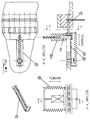
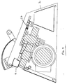
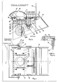
- a machine 50 comprises a binding element hanging and closure mechanism 18,12 at the front end and a punching mechanism 25,27,28 at the rear end, which are both powered from a central drive shaft 24 and associated cam 11 with eccentric end 24a, mounted intermediate the two mechanisms.
- a guard 35 acts as both safety shield and machine enables, revealing control console 36 when pivoted downwards. As shown in Figure 12, the guard 35 is in the up position, in which power is isolated from the drive assembly and the control console 36 is shielded under the main cover 39, thus inhibiting operation of the machine.
- the guard 35 is moved manually into the down position, which movement in turn moves the closer arm 12 into the down position - the over centre action of the guard spring 37 and the weight of the guard 35 together act to hold the closer arm 12 in position when the operator releases the guard 35.
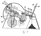
- a deep, A-shaped open-topped confetti storage container 31 is located towards the rear of the machine, underneath the punching mechanism.
- the main parts of the hanging/closure mechanism comprise a pivoting flap 18 mounted for pivotal movement about pivot axis 18a (see Figure 22).
- a wire binding element 52 of the kind set forth is offered up to the machine and pushed by the operator against the flap 18, the latter pivots inwardly, and since the pivot axis 18a is a short distance in front of the flap 18, the lower edge of the flap is lifted up.
- the wire element 52 is then slid down the front face of the flap 18 until the individual fingers in the finger plate 5 engage with the blunts in the binding element 52, the blunts resting on the fingers such that contact between the binding element and the pivoting flap is broken, allowing the flap to pivot under gravity back to its original, equilibrium position.
- Figure 23 in which position pre-punched paper sheets 60 are hung on the binding element 52.
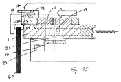
- the closer arm 12 is pivoted downwardly, by moving the guard 35 manually downwards and towards the operator (thus revealing control console 36 and allowing power-up of the machine) until the inner angle of the closer arm engages with the stop 13. Then, as shown in Figure 25, the base plate 1 along with all its attachments is pushed, in the direction shown by the large arrow, by activation of the main closing cam 11, towards the inner face 12a of the closer arm 12. In this position the closer arm locking pin 14 is above the angle on the closer arm 12, thus restricting any angular movement and effectively locking the closer arm in the down position.
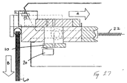
- the closer arm 12 is then allowed to return to the up position as shown in Figure 28, under the action of springs 38, ready for the next binding operation.
- control console 36 In this position, the control console 36 is exposed and power is connected to the main drive assembly, as has been previously described.
- the adjustment mechanism is described in detail hereinafter
- paper is dropped into the punch die 28, using the paper support 40 (see Figure 14).
- two button type switches located at each end of the console 36 are pressed simultaneously (necessitating two handed operation to avoid possibility of inserting fingers into machine during punching), thereby activating the main drive which in turn rotates cam shaft 24.
- cam shaft 24 locates within a slot 25a in the punch drive plate 25, such that when the cam shaft rotates the plate 25 moves in a linear motion which pushes the punch pins 27 through the die 28 and the paper 62 therein (see Figure 15).
- the cam 10 hits the limit switch 20 the drive is reversed until the plates 1 and 25 resume their original position.
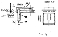
- At least one of the pins 27 is provided with a recess into which the pin is pushed by contact with the paper, but the pin is normally prevented (during A4 operation) from entering this recess by means of solenoid plunger 32.
- the punch pin return finger spring 42 is in tension, pulling the punch pin return finger 41 to a position which allows the solenoid plunger 32 to pass through a slot running along its length.
- the solenoid is de-energised and the solenoid return spring assembly 43 in tension, thereby pulling the solenoid plunger 32 through the punch pin return finger 41 into the opposing hole, making a rigid face behind the pin 27. In this position, when the punch drive plate 25 is activated the assembly pushes the punch pin 27 through the paper, as shown in Figure 4.
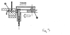
- the plunger 32 is retracted into its housing 32a, thus removing the main support from behind the punch pin (see Figure 6).
- activation of the punch drive plate 25 pushes the pin 27 towards the paper, and when contact is made the paper resistance pushes the punch pin return finger 41 back into its slot, against the action of the punch pin return finger spring 42 which stops the hole from being punched (see Figure 7).
- the punch drive plate 25 retracts, the punch pin return finger 41 pushes against the head of punch pin 27, pushing it back into the die 28.
- the punch pin return finger is back in its original position in which it can accept the A5 disable solenoid plunger 32.
- the machine is adapted to accept all binding element sizes from small ones used to bind calendars and the like, to large ones suitable for binding documents over 25mm thick. It is important to adjust the machine to the correct wire setting in order to allow the binding element 52 to sit horizontally when loaded in the machine, and this is achieved by positioning the retaining flap 18 with respect to the base plate 1.
- the retaining flap pivot 18a is attached to upper plate 4 and this upper plate 4 is moved relative to base plate 1 to effect the flap position adjustment.
- Rotation of the wire size adjustment cam 9 puts a force on the upper plate adjustment stop block 7. Stop block 7 is attached to upper plate 4 and so rotation of cam 9 is translated into movement of upper plate 4 (and hence pivot axis 18a) relative to base plate 1.
- the cam 9 is rotated by use of a stepper motor 21 located in the base plate 1, the stepper motor being activated from the main unit controller.
- a stepper motor 21 located in the base plate 1, the stepper motor being activated from the main unit controller.
- This is shown schematically in Figure 2, comprising keypad 36a and controller with inputs 36b through 36m and outputs 36n through 36t as follows:-
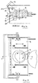
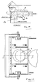
- the operator enters the wire size on a keypad on console 36, this in turn rotates the cam 9 via the stepper motor 21 until cam 9 is in the correct position for the selected wire size setting (as measured from cam datum pin 9a)- the smaller the wire size the larger the closing stroke as measured by the distance travelled by base plate 1 towards closer arm surface 12a.
- the shaft of the stepper motor 21 extends downwardly from the bottom of the motor, where closing travel adjustment cam 10 is mounted for rotation with the motor shaft, thereby giving the required setting.
- the drive is reversed when cam 10 hits limit switch 20, automatically releasing the bound document and returning the base plate 1 and all its attachments to the original position, as described above.
- Figures 18 and 19 illustrate the positions of cams 9 and 10 when set for the largest wire size (i.e shortest stroke), and Figures 20 and 21 show the positions of these items when set for the smallest wire size (longest stroke).
- the machine according to the present invention will mainly be used for punching and binding in two, separate operations the unique arrangement of the punching and binding mechanisms whereby both are activated simultaneously with a single drive mechanism means that for small wire sizes at least, simultaneous punching and binding is possible. It is believed that this capability for simultaneous punching and binding is both novel and inventive, as it allows for much faster operation in a mass production situation - the operator can thus bind the previously punched document at the same time as punching the next set of pages to be bound, speeding up the process considerably.
Landscapes
- Engineering & Computer Science (AREA)
- Textile Engineering (AREA)
- Folding Of Thin Sheet-Like Materials, Special Discharging Devices, And Others (AREA)
- Basic Packing Technique (AREA)
Applications Claiming Priority (2)
| Application Number | Priority Date | Filing Date | Title |
|---|---|---|---|
| GB9901990 | 1999-01-30 | ||
| GBGB9901990.3A GB9901990D0 (en) | 1999-01-30 | 1999-01-30 | Improvememts in and relating to wire binding machines |
Publications (2)
| Publication Number | Publication Date |
|---|---|
| EP1031434A2 true EP1031434A2 (fr) | 2000-08-30 |
| EP1031434A3 EP1031434A3 (fr) | 2000-09-06 |
Family
ID=10846734
Family Applications (1)
| Application Number | Title | Priority Date | Filing Date |
|---|---|---|---|
| EP00300696A Withdrawn EP1031434A3 (fr) | 1999-01-30 | 2000-01-28 | Dispositif pour relier des blocs de feuilles avec des peignes de brochage |
Country Status (3)
| Country | Link |
|---|---|
| US (1) | US6332742B1 (fr) |
| EP (1) | EP1031434A3 (fr) |
| GB (2) | GB9901990D0 (fr) |
Cited By (7)
| Publication number | Priority date | Publication date | Assignee | Title |
|---|---|---|---|---|
| DE10059344A1 (de) * | 2000-11-29 | 2002-06-06 | Heidelberger Druckmasch Ag | Verfahren zum Herstellen von Broschüren beliebiger Formate und Dicken mittels Drahtkammbindung |
| WO2002055312A1 (fr) | 2001-01-10 | 2002-07-18 | Kevin Smith | Dos de reliure spirale |
| DE10119009A1 (de) * | 2001-04-18 | 2002-10-24 | Attalus S A | Halbautomatisches Drahtbindegerät |
| DE10141811A1 (de) * | 2001-08-27 | 2003-03-20 | Heidelberger Druckmasch Ag | Vorrichtung zum flexiblen Herstellen von Drahtbindeelementen für das Binden von Broschüren beliebiger Formate und Dicken mittels Drahtkammbindung |
| US9862221B2 (en) | 2011-07-18 | 2018-01-09 | ACCO Brands Corporation | Binding system for retaining bound components |
| CN110682709A (zh) * | 2019-09-27 | 2020-01-14 | 安徽浩杨机械有限公司 | 一种用于装订机的墙板 |
| WO2022159812A1 (fr) | 2021-01-22 | 2022-07-28 | Fellowes, Inc. | Dispositif multi-fonctionnel de reliure de documents |
Families Citing this family (2)
| Publication number | Priority date | Publication date | Assignee | Title |
|---|---|---|---|---|
| US20020106265A1 (en) * | 2000-11-29 | 2002-08-08 | Mario Litsche | Binding apparatus and method |
| USD467609S1 (en) | 2001-07-09 | 2002-12-24 | Carl Jimuki Kabushiki Kaisha | Rod used for a jig for binding perforated paper sheets on a ring binder |
Family Cites Families (6)
| Publication number | Priority date | Publication date | Assignee | Title |
|---|---|---|---|---|
| DE3941648A1 (de) | 1989-12-16 | 1991-06-20 | Renz Chr Gmbh & Co | Vorrichtung zum einkaemmen und binden von gestanzten einzelblaettern |
| GB9210553D0 (en) * | 1992-05-18 | 1992-07-01 | Burn James Int Ltd | Improvements in and relating to binding perforated sheets |
| US5249902A (en) * | 1992-06-25 | 1993-10-05 | The Holson Burnes Company | Loose-leaf binder assembly process and apparatus |
| US5931623A (en) * | 1994-10-11 | 1999-08-03 | Unicoil, Inc. | Spiral binding method and apparatus |
| US5785479A (en) * | 1996-03-26 | 1998-07-28 | General Binding Corporation | Automated spiral binding machine |
| GB9712718D0 (en) | 1997-06-18 | 1997-08-20 | Heights Design Production Ltd | Binding apparatus |
-
1999
- 1999-01-30 GB GBGB9901990.3A patent/GB9901990D0/en not_active Ceased
-
2000
- 2000-01-28 US US09/494,261 patent/US6332742B1/en not_active Expired - Fee Related
- 2000-01-28 EP EP00300696A patent/EP1031434A3/fr not_active Withdrawn
- 2000-01-28 GB GB0001952A patent/GB2348623B/en not_active Expired - Fee Related
Cited By (9)
| Publication number | Priority date | Publication date | Assignee | Title |
|---|---|---|---|---|
| DE10059344A1 (de) * | 2000-11-29 | 2002-06-06 | Heidelberger Druckmasch Ag | Verfahren zum Herstellen von Broschüren beliebiger Formate und Dicken mittels Drahtkammbindung |
| WO2002055312A1 (fr) | 2001-01-10 | 2002-07-18 | Kevin Smith | Dos de reliure spirale |
| DE10119009A1 (de) * | 2001-04-18 | 2002-10-24 | Attalus S A | Halbautomatisches Drahtbindegerät |
| DE10141811A1 (de) * | 2001-08-27 | 2003-03-20 | Heidelberger Druckmasch Ag | Vorrichtung zum flexiblen Herstellen von Drahtbindeelementen für das Binden von Broschüren beliebiger Formate und Dicken mittels Drahtkammbindung |
| US9862221B2 (en) | 2011-07-18 | 2018-01-09 | ACCO Brands Corporation | Binding system for retaining bound components |
| US10569590B2 (en) | 2011-07-18 | 2020-02-25 | ACCO Brands Corporation | Binding system for retaining bound components |
| CN110682709A (zh) * | 2019-09-27 | 2020-01-14 | 安徽浩杨机械有限公司 | 一种用于装订机的墙板 |
| WO2022159812A1 (fr) | 2021-01-22 | 2022-07-28 | Fellowes, Inc. | Dispositif multi-fonctionnel de reliure de documents |
| EP4281291A4 (fr) * | 2021-01-22 | 2024-09-04 | Fellowes, Inc. | Dispositif multi-fonctionnel de reliure de documents |
Also Published As
| Publication number | Publication date |
|---|---|
| US6332742B1 (en) | 2001-12-25 |
| GB9901990D0 (en) | 1999-03-17 |
| GB2348623A (en) | 2000-10-11 |
| GB2348623B (en) | 2003-03-05 |
| GB0001952D0 (en) | 2000-03-22 |
| EP1031434A3 (fr) | 2000-09-06 |
Similar Documents
| Publication | Publication Date | Title |
|---|---|---|
| US6332742B1 (en) | Wire binding machine | |
| US3114475A (en) | Vending machine | |
| US8667889B2 (en) | Machine for the preparation of beverages by infusion using cartridges | |
| CN103096864B (zh) | 药片分割装置 | |
| US3180518A (en) | Mechanical vendor for articles | |
| RU2485038C2 (ru) | Дозатор или подобные раздаточные емкости | |
| US2211511A (en) | Button feeding device for sewing machines | |
| GB2049405A (en) | Automatic coffee machine | |
| US4043484A (en) | Newspaper vending machine | |
| US1028458A (en) | Vending-machine. | |
| CN112192514A (zh) | 电动订书机 | |
| US2432415A (en) | Newspaper dispensing apparatus | |
| KR100943378B1 (ko) | 단추구멍내기 재봉기의 밑실 절단 장치 및 단추구멍내기재봉기 | |
| AU593157B2 (en) | Paper punching machine | |
| CN209551861U (zh) | 一种切书机 | |
| US2491615A (en) | Newspaper rack | |
| US4175989A (en) | Newspaper vending machine | |
| US4706842A (en) | Apparatus for dispensing elongated cylindrical objects such as pencils | |
| US2672930A (en) | Motor-driven envelope opener | |
| US3474491A (en) | Molding apparatus with stacker means | |
| US3040328A (en) | Apparatus for inserting hooks in drapery and the like | |
| US2625225A (en) | Card punch and verifier | |
| US3319822A (en) | Vending machine discharge means | |
| US3129651A (en) | Automatic toaster | |
| US3380640A (en) | Stapling machines |
Legal Events
| Date | Code | Title | Description |
|---|---|---|---|
| PUAI | Public reference made under article 153(3) epc to a published international application that has entered the european phase |
Free format text: ORIGINAL CODE: 0009012 |
|
| PUAL | Search report despatched |
Free format text: ORIGINAL CODE: 0009013 |
|
| AK | Designated contracting states |
Kind code of ref document: A2 Designated state(s): AT BE CH CY DE DK ES FI FR GB GR IE IT LI LU MC NL PT SE |
|
| AX | Request for extension of the european patent |
Free format text: AL;LT;LV;MK;RO;SI |
|
| AK | Designated contracting states |
Kind code of ref document: A3 Designated state(s): AT BE CH CY DE DK ES FI FR GB GR IE IT LI LU MC NL PT SE |
|
| AX | Request for extension of the european patent |
Free format text: AL;LT;LV;MK;RO;SI |
|
| AKX | Designation fees paid |
Free format text: AT BE CH CY DE DK ES FI FR GB GR IE IT LI LU MC NL PT SE |
|
| 17P | Request for examination filed |
Effective date: 20010306 |
|
| RBV | Designated contracting states (corrected) |
Designated state(s): AT BE CH CY DE DK ES FI FR GB GR IE IT LI LU MC NL PT SE |
|
| 17Q | First examination report despatched |
Effective date: 20030303 |
|
| GRAP | Despatch of communication of intention to grant a patent |
Free format text: ORIGINAL CODE: EPIDOSNIGR1 |
|
| STAA | Information on the status of an ep patent application or granted ep patent |
Free format text: STATUS: THE APPLICATION IS DEEMED TO BE WITHDRAWN |
|
| 18D | Application deemed to be withdrawn |
Effective date: 20040613 |
|
| R18D | Application deemed to be withdrawn (corrected) |
Effective date: 20040615 |