EP1031464A2 - Dispositif pour éclairer un local, un corps ou une surface - Google Patents
Dispositif pour éclairer un local, un corps ou une surface Download PDFInfo
- Publication number
- EP1031464A2 EP1031464A2 EP00103113A EP00103113A EP1031464A2 EP 1031464 A2 EP1031464 A2 EP 1031464A2 EP 00103113 A EP00103113 A EP 00103113A EP 00103113 A EP00103113 A EP 00103113A EP 1031464 A2 EP1031464 A2 EP 1031464A2
- Authority
- EP
- European Patent Office
- Prior art keywords
- light
- enveloping
- lens
- emitting diode
- lens body
- Prior art date
- Legal status (The legal status is an assumption and is not a legal conclusion. Google has not performed a legal analysis and makes no representation as to the accuracy of the status listed.)
- Withdrawn
Links
Images


Classifications
-
- F—MECHANICAL ENGINEERING; LIGHTING; HEATING; WEAPONS; BLASTING
- F21—LIGHTING
- F21V—FUNCTIONAL FEATURES OR DETAILS OF LIGHTING DEVICES OR SYSTEMS THEREOF; STRUCTURAL COMBINATIONS OF LIGHTING DEVICES WITH OTHER ARTICLES, NOT OTHERWISE PROVIDED FOR
- F21V5/00—Refractors for light sources
- F21V5/04—Refractors for light sources of lens shape
-
- F—MECHANICAL ENGINEERING; LIGHTING; HEATING; WEAPONS; BLASTING
- F21—LIGHTING
- F21V—FUNCTIONAL FEATURES OR DETAILS OF LIGHTING DEVICES OR SYSTEMS THEREOF; STRUCTURAL COMBINATIONS OF LIGHTING DEVICES WITH OTHER ARTICLES, NOT OTHERWISE PROVIDED FOR
- F21V13/00—Producing particular characteristics or distribution of the light emitted by means of a combination of elements specified in two or more of main groups F21V1/00 - F21V11/00
- F21V13/02—Combinations of only two kinds of elements
-
- G—PHYSICS
- G02—OPTICS
- G02B—OPTICAL ELEMENTS, SYSTEMS OR APPARATUS
- G02B6/00—Light guides; Structural details of arrangements comprising light guides and other optical elements, e.g. couplings
- G02B6/0001—Light guides; Structural details of arrangements comprising light guides and other optical elements, e.g. couplings specially adapted for lighting devices or systems
- G02B6/0005—Light guides; Structural details of arrangements comprising light guides and other optical elements, e.g. couplings specially adapted for lighting devices or systems the light guides being of the fibre type
- G02B6/0006—Coupling light into the fibre
-
- F—MECHANICAL ENGINEERING; LIGHTING; HEATING; WEAPONS; BLASTING
- F21—LIGHTING
- F21W—INDEXING SCHEME ASSOCIATED WITH SUBCLASSES F21K, F21L, F21S and F21V, RELATING TO USES OR APPLICATIONS OF LIGHTING DEVICES OR SYSTEMS
- F21W2106/00—Interior vehicle lighting devices
-
- F—MECHANICAL ENGINEERING; LIGHTING; HEATING; WEAPONS; BLASTING
- F21—LIGHTING
- F21W—INDEXING SCHEME ASSOCIATED WITH SUBCLASSES F21K, F21L, F21S and F21V, RELATING TO USES OR APPLICATIONS OF LIGHTING DEVICES OR SYSTEMS
- F21W2107/00—Use or application of lighting devices on or in particular types of vehicles
- F21W2107/30—Use or application of lighting devices on or in particular types of vehicles for aircraft
-
- F—MECHANICAL ENGINEERING; LIGHTING; HEATING; WEAPONS; BLASTING
- F21—LIGHTING
- F21Y—INDEXING SCHEME ASSOCIATED WITH SUBCLASSES F21K, F21L, F21S and F21V, RELATING TO THE FORM OR THE KIND OF THE LIGHT SOURCES OR OF THE COLOUR OF THE LIGHT EMITTED
- F21Y2115/00—Light-generating elements of semiconductor light sources
- F21Y2115/10—Light-emitting diodes [LED]
Definitions
- the invention relates to a device for illuminating or illuminating rooms, Bodies or surfaces according to the preamble of claim 1.
- White light-emitting diodes are preferably provided for the light-emitting diodes, which are units formed from two-colored or multi-colored light-emitting diodes or can act from so-called luminescence conversion diodes.
- DE 195 14 424 A1 shows two different ones Lenses compatible lenses for the light of a vehicle to use. It is a motor vehicle position lamp with a lens that can be used for both light-emitting diodes and light bulbs was created. The lens was therefore designed to be one Set of stages for each of the different light sources has a desired one To cause scattering of the light source.
- this disclosure is note that it is only a position lamp, d. H., that only so much light is emitted to limit a vehicle to recognize the taillights. Illumination or illumination of a surface or area Body is not aimed at with this disclosed lamp, which is why this Luminaire can be assigned to the area of passive luminaires.
- WO 97/26483 discloses a light emitting diode device for use in signal lamps or traffic lights. This publication is also about Principle about having enough light available in different colors in order to be clearly recognized. For this purpose there are several rows of LEDs have been arranged through a lens with appropriate steps be covered. Through these gradations in the lens it is achieved that Light is emitted at certain angles to the beam axis, thereby to be clearly visible from different angles and all weather influences.
- EP 0 523 927 B1 describes a fluorescent lamp with a lens.
- a lens element for a LED at least two facets, d. H. Has lens body. Through the A desired output beam is formed by refraction of the facets.
- the light source is designated by 1, which according to the invention is a light-emitting diode.
- the light-emitting diode 1 has a front, essentially spherical light exit surface 2.
- narrow-focusing light-emitting diodes 1 LED
- a lens 4 is located in a main plane 3 at a selectable and adjustable distance from the object plane 7 of the light-emitting diode 1.
- a further adjustable distance in front of this lens 4 with the main plane 3 shows the image plane 5, which, like the main plane 3, is perpendicular to the optical one Beam path 6 is arranged.
- the distance between the object plane 7 of the light-emitting diode 1 and the main plane 3 of the lens 4 is denoted by S 0
- the distance between the main plane 3 of the lens 4 and the image plane 5 has the reference symbol S 1 .
- the distances S 0 to S 1 behave approximately as 100: 1.
- the ratio depends on the area to be illuminated in the image plane 5.
- the optical beam path 6 extends from the light source 1 through the lens 4 to the image plane 5 in a continuous, here horizontally drawn plane.
- the light rays 8 emerging on the outer circumference of the light-emitting diode 1 run parallel to the optical beam path 6 up to the entry into the main plane 3 of the lens 4.
- the light beams 8 are deflected in the lens 4 in accordance with the optical laws and meet at a uniform radial distance from the optical beam path 6 onto the image plane 5 and thereby mark the light source on the image plane 5 on a correspondingly enlarged scale.
- the optical beam path impinges on the image plane 5 at the point 9, and the two deflected beams 8 mark the outer points 10 on the image plane 5, the distance from each other of which represents the diameter of the imaged light source on the image plane 5.
- the light beam 8 running parallel to the optical beam path 6 emerges at point 11 from the object plane.
- the light beam 8 running at point 11 emerges from the object plane of the light-emitting diode 1 at point 11. From the same point 11 on the object plane, the optical beam 12 is taken, which runs through the center of the lens 4 and in turn ends exactly at point 10 on the image plane 5.
- the third light beam 13 from the starting point 11 arrives in the lower edge region of the lens 4 and is deflected in such a way that it also strikes the point 10 of the image plane.
- the light rays 8, 12, 13 with the starting point 11 and the impact point 10 are subject to the condition that , where f is the focal length of the lens 4.
- the light source namely the light-emitting diode 1
- the light source is imaged on the image plane.
- the imaging scale of the light source on the LED lens is approximately 10: 1
- the imaging scale for the light source in the image plane 5 is approximately 10: 1.
- the lens 4 is preferably in a socket of hexagonal cross section.
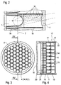
- FIG. 2 shows a detail of a lamp element on an enlarged scale.
- the light-emitting diode 1 as the light source is inserted in a corresponding socket with an electrical connection on the bottom.
- the lens 4 which in this example is designed as a lens body running over a plurality of light-emitting diodes.
- the optical beam path 6 runs according to FIG. 1 in a horizontal line through the light-emitting diode 1 and lens 4.
- an enveloping body 14 which surrounds the light-emitting diode 1 relatively closely in the lower region and approximately in the region of the object plane 7 in a slightly conical opening is shaped.
- the enveloping body 14 ends axially at a short distance in front of the light-emitting diode 1.
- a tubular element 15 is placed flush on the front side of the enveloping body 14 and its front end side stands up on the lens body 4.
- the envelope body 14 and the tubular element 15 can also be designed as a one-piece envelope element.
- the light rays 16 emanating from the light-emitting diode 1 run almost radially in the lower region of the light-emitting diode and hit the inner surface of the enveloping body 14. Since the surface of the enveloping body and also of the tubular element are designed in a non-reflecting manner, these light rays 16 are swallowed on the inner surface of the envelope.
- the light rays 16 emerge at a constantly decreasing angle and hit the inner surfaces of the enveloping body 14 and the tubular element 15 without being reflected. Only the light rays 16 emerging in a limited spherical front region of the light-emitting diode 1 hit the lens 4 arranged at a distance unhindered and are emitted from there onto the image plane 5.
- This structure of the lamp element clearly shows that the stray light from the light-emitting diode 1 is swallowed, while only active light is transmitted to the lens in accordance with the aperture effect.
- the Lenses 4 and also the enveloping body 14 with the tubular elements 15 in Cross-section are hexagonal.
- This hexagonal cross section allows an immediate close arrangement of the lenses 4 or the enveloping body 14 in this way, in a relatively small overall cross section of the reading light 17 a large number of light-emitting diodes 1 with lenses 4 can be accommodated. Thereby the desired minimum number of light-emitting diodes 1 of approximately 60 light-emitting diodes to be built in.
- the individual lenses 4 or the enveloping body 14 and the tubular elements 15 other cross sections are also possible, for example square, round or triangular Cross sections. However, it must be accepted that the Number of LEDs 1 to be accommodated is smaller and that between the individual light emitting diodes 1 with lenses 4 cavities that cannot be filled remain.
- the reading lamp 17 has a bottom side Cover 18 provided.
- the cover 18 on the bottom side adjoins FIG Axial direction a tubular jacket 19 in which the disc-shaped receptacle 20 is used for the light emitting diodes 1.
- the LEDs 1 are with their Legs 21 in the receptacle 20 mechanically fixed and electrically connected used.
- the enveloping bodies 14 with the tubular ones attached at the front Elements The tubular elements 15 close to the integrally formed Lens body 4 on the face of an annular collar of the Jacket 19 is bordered.
- the essentially honeycomb formation and type order of the enveloping body 14 with the tubular elements 15 serves at the same time also for centering the light-emitting diodes 1, the main task of these enveloping bodies 14 and tubular elements 15, however, consists of light rays each single light emitting diode focused on the lenses 4 to send.
- the enveloping body 14 as a whole mechanical Centering for the light emitting diodes 1 and the tubular body as an aperture and to be seen as a spacer for the hexagonal lens body 4.
- the lenses 4 are usually parallel to each other. However, they can also be rotated or tilted just as well, thereby deflecting the light beams down to light beams which are aimed at a single center point.
- the light beams emerging from the multiplicity of light-emitting diodes 1 of the reading light 17 overlap to form a single, essentially round light spot.
- all the circles of the light-emitting diodes 1 with lens 4 that can be seen in the front view of the reading lamp 17 overlap in the image plane 5 to form a single common light spot.
- This mode of operation is achieved in that corresponding distance ratios from the light-emitting diode 1 to the lens 4 and to the image plane 5 at a focal length according to the above-mentioned formula of be respected.
- the light-emitting diode arranged in the center in the front view according to FIG. 3 with only slight side differences forms the same light spot as the light-emitting diode 1 provided on the outer edge in the front view of the reading lamp 17.
- only this active light from the light-emitting diodes also permits the reading of printed matter which is held approximately in the image plane 5.
- FIGS. 5, 6 and 7 show possible arrangements of the light sources or LEDs 1 shown in plan view.
- Figure 5 gives way to the top view from Figure 3 in that in Figure 5 square lens body or envelope 14 are shown. From the comparison of Figures 5 and 3 it can be seen that the hexagonal cross-sectional shape of the lens body 4 with enveloping bodies 14 a more compact Arrangement allows.
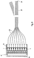
- the light emerging from the light-emitting diodes 1 was Imaged freely on an image plane 5 via lens body 4.
- the emerging from the individual light emitting diodes 1 in to couple as many light guides 23. So that each LED 1 as a light source the reading lamp 17 connected to a light guide 23. The light can come on are guided in this way over a relatively long distance to a light exit 24, which is designed as a flexible light guide end piece 25 and thereby for the Light exit has an adjustment range.
- the light guide 23 can over individual Coupling elements on the light emitting diodes 1 or with an overall coupling be plugged onto the LEDs 1.
- FIG. 9 shows the insertion of the light guides 23 onto the light-emitting diodes 1.
- the mounting of the light guide 23 in the enveloping bodies 14 can be done mechanically by clamping, friction or by gluing.
Landscapes
- Physics & Mathematics (AREA)
- Engineering & Computer Science (AREA)
- General Engineering & Computer Science (AREA)
- General Physics & Mathematics (AREA)
- Optics & Photonics (AREA)
- Non-Portable Lighting Devices Or Systems Thereof (AREA)
- Led Device Packages (AREA)
- Securing Globes, Refractors, Reflectors Or The Like (AREA)
Applications Claiming Priority (2)
| Application Number | Priority Date | Filing Date | Title |
|---|---|---|---|
| DE19908040A DE19908040A1 (de) | 1999-02-24 | 1999-02-24 | Einrichtung zur Beleuchtung von Räumen, Körpern oder Flächen |
| DE19908040 | 1999-02-24 |
Publications (2)
| Publication Number | Publication Date |
|---|---|
| EP1031464A2 true EP1031464A2 (fr) | 2000-08-30 |
| EP1031464A3 EP1031464A3 (fr) | 2003-07-09 |
Family
ID=7898749
Family Applications (1)
| Application Number | Title | Priority Date | Filing Date |
|---|---|---|---|
| EP00103113A Withdrawn EP1031464A3 (fr) | 1999-02-24 | 2000-02-16 | Dispositif pour éclairer un local, un corps ou une surface |
Country Status (3)
| Country | Link |
|---|---|
| US (1) | US6520666B1 (fr) |
| EP (1) | EP1031464A3 (fr) |
| DE (1) | DE19908040A1 (fr) |
Cited By (4)
| Publication number | Priority date | Publication date | Assignee | Title |
|---|---|---|---|---|
| EP1496380A1 (fr) * | 2003-07-09 | 2005-01-12 | Diehl Luftfahrt Elektronik GmbH | Elément d'éclairage avec diode électroluminescente |
| EP1767967A2 (fr) | 2005-09-26 | 2007-03-28 | Osram Sylvania Inc. | Lampe Del avec couplage optique direct avec un guide de lumière optique ayant une pluralité de tuyaux de lumière dans un agencement axial |
| AT513917A1 (de) * | 2013-02-05 | 2014-08-15 | Zizala Lichtsysteme Gmbh | Leuchteinheit für einen Scheinwerfer sowie Scheinwerfer |
| WO2018069175A1 (fr) * | 2016-10-11 | 2018-04-19 | HELLA GmbH & Co. KGaA | Dispositif d'éclairage pour un véhicule |
Families Citing this family (49)
| Publication number | Priority date | Publication date | Assignee | Title |
|---|---|---|---|---|
| DE19926561A1 (de) | 1999-06-11 | 2000-12-14 | Diehl Stiftung & Co | Strahler, insbesondere Leseleuchte in Kabinen von Fahrzeugen |
| DE20019923U1 (de) * | 2000-11-23 | 2002-01-10 | Siemens AG, 80333 München | Aufbausystem zur Aufnahme von LED-Modulen sowie LED-Modul zur Aufnahme in einem Aufbausystem |
| DE20101028U1 (de) | 2001-01-20 | 2001-05-10 | Zweibrüder Stahlwarenkontor GmbH, 42697 Solingen | Taschenlampe, insbesondere Tischlampe oder Präsentationsteller |
| DE10131686A1 (de) * | 2001-06-29 | 2003-01-16 | Mellert Fa Hermann | Taschenlampe |
| US6871981B2 (en) * | 2001-09-13 | 2005-03-29 | Heads Up Technologies, Inc. | LED lighting device and system |
| DE10147236A1 (de) * | 2001-09-26 | 2003-04-30 | Kastriot Merlaku | Videoleuchte mit Leuchtdioden |
| DE10147235A1 (de) * | 2001-09-26 | 2003-04-30 | Kastriot Merlaku | Kameraleuchte mit Leuchtdioden |
| JP3984023B2 (ja) * | 2001-11-02 | 2007-09-26 | 株式会社小糸製作所 | 車輌用灯具 |
| DE10204939A1 (de) * | 2002-02-07 | 2003-09-04 | Parsytec Comp Gmbh | Vorrichtung und Verfahren zur Erzeugung von flächigem parallelen Licht |
| DE10208111B4 (de) * | 2002-02-26 | 2006-04-13 | Kastriot Merlaku | Innenbeleuchtungssystem für ein Flugzeug |
| DE10208109B4 (de) * | 2002-02-26 | 2006-04-13 | Kastriot Merlaku | Innenbeleuchtungssytem für einen Hubschrauber |
| US20030189836A1 (en) * | 2002-04-04 | 2003-10-09 | Sparling Teddy Burch | Boat trailer employing immersible fiber-optic lighting means |
| JP3619850B2 (ja) * | 2002-04-08 | 2005-02-16 | 株式会社キャットアイ | 自転車用ヘッドランプ |
| JP2004047351A (ja) * | 2002-07-15 | 2004-02-12 | Koito Mfg Co Ltd | 車両用灯具 |
| US7334918B2 (en) * | 2003-05-07 | 2008-02-26 | Bayco Products, Ltd. | LED lighting array for a portable task light |
| US20050128761A1 (en) * | 2003-12-10 | 2005-06-16 | Shih-Hsiung Wu | Turn signal light using light-emitting diodes as light sources |
| US7097336B2 (en) * | 2004-05-28 | 2006-08-29 | Yu-Chu Lin | Auxiliary light ring device for a vehicular light |
| US7070311B2 (en) * | 2004-06-03 | 2006-07-04 | Fu An Industrial Co., Ltd. | Vehicle light for producing light whose form depends on orientations of plural refraction elements |
| DE102004031858A1 (de) * | 2004-07-01 | 2006-01-19 | Automotive Lighting Reutlingen Gmbh | Linsenanordnung und Kraftfahrzeugscheinwerfer oder Kraftfahrzeugleuchte mit einer solchen Linsenanordnung |
| DE112005001752B4 (de) * | 2004-07-20 | 2012-03-01 | Magna Marque International Inc. | Fahrradbeleuchtungssystem |
| US7450085B2 (en) * | 2004-10-07 | 2008-11-11 | Barco, Naamloze Vennootschap | Intelligent lighting module and method of operation of such an intelligent lighting module |
| JP4050271B2 (ja) * | 2004-12-07 | 2008-02-20 | シャープ株式会社 | 対物レンズホルダー、それを備えた対物レンズ駆動装置、及び光ディスク記録再生装置 |
| US20070035955A1 (en) * | 2005-01-27 | 2007-02-15 | Airbus Deutschland Gmbh | Light for use for a passenger seat |
| US20060268548A1 (en) * | 2005-05-25 | 2006-11-30 | Haoli Precision Industrial Co., Ltd. | LED lighting device with light converging effect |
| JP2009501451A (ja) * | 2005-07-12 | 2009-01-15 | マグナ インターナショナル インコーポレイテッド | 自動車用照明のための半導体光エンジン |
| US20070121333A1 (en) * | 2005-11-30 | 2007-05-31 | Ronald Woodward | Semiconductor light engine for automotive lighting |
| US20070225778A1 (en) * | 2006-03-23 | 2007-09-27 | Heacock Gregory L | PDT apparatus with an addressable LED array for therapy and aiming |
| US7566154B2 (en) * | 2006-09-25 | 2009-07-28 | B/E Aerospace, Inc. | Aircraft LED dome light having rotatably releasable housing mounted within mounting flange |
| DE202006016879U1 (de) * | 2006-11-04 | 2008-03-13 | Alfavision Gmbh & Co. Kg | Modularer Messscanner |
| EP2095011A1 (fr) * | 2006-12-04 | 2009-09-02 | Cree Led Lighting Solutions, Inc. | Ensemble éclairage et procédé d'éclairage |
| DE102007017343B4 (de) | 2007-04-12 | 2010-05-12 | Airbus Deutschland Gmbh | Leseleuchte mit Streulichtunterdrückung |
| US7635213B2 (en) * | 2008-02-07 | 2009-12-22 | Ching-Liang Lee | Vehicle light assembly |
| US8430526B2 (en) * | 2008-08-29 | 2013-04-30 | Northrop Grumman Systems Corporation | Method and apparatus for producing a uniform irradiance distribution from an array of light emitting diodes |
| US20100097803A1 (en) * | 2008-10-20 | 2010-04-22 | Wu Ming-Chang | Multiple Light Source Surface Packaging Structure |
| TW201040447A (en) * | 2009-03-13 | 2010-11-16 | Koninkl Philips Electronics Nv | Pattern-projecting light-output system |
| DE202009006261U1 (de) * | 2009-04-29 | 2010-09-16 | Zumtobel Lighting Gmbh | LED-Leuchte |
| JP5677422B2 (ja) * | 2009-06-17 | 2015-02-25 | エルジー・ケム・リミテッド | 有機発光素子 |
| TWI426302B (zh) * | 2010-02-12 | 2014-02-11 | Au Optronics Corp | 顯示裝置及其增光膜 |
| US8348484B2 (en) * | 2010-04-22 | 2013-01-08 | Ford Global Technologies, Llc | Vehicle exterior lamp |
| DE102010039859A1 (de) * | 2010-08-27 | 2012-03-01 | Osram Ag | Leseleuchte für Kraftfahrzeuge |
| US9343002B2 (en) * | 2011-08-19 | 2016-05-17 | Luminator Holding L.P. | Window including integrated display signage |
| US8608344B2 (en) * | 2011-09-06 | 2013-12-17 | Asia Vital Components Co., Ltd. | LED lighting structure |
| US9500340B2 (en) | 2011-10-25 | 2016-11-22 | A-Dec, Inc. | Dental light using LEDs |
| DE102011085978A1 (de) * | 2011-11-09 | 2013-05-16 | Osram Gmbh | Laser-leuchtstoff-vorrichtung mit laserarray |
| US8899786B1 (en) * | 2012-05-04 | 2014-12-02 | Cooper Technologies Company | Method and apparatus for light square assembly |
| US10384803B2 (en) * | 2016-10-07 | 2019-08-20 | The Boeing Company | Methods and devices for light distribution in an aircraft, and aircraft including such devices |
| KR101937974B1 (ko) * | 2018-05-08 | 2019-01-14 | 주식회사 에이엘테크 | 광섬유 발광형 표지 장치 |
| EP3647654A1 (fr) * | 2018-10-31 | 2020-05-06 | Valeo Iluminacion, S.A. | Dispositif d'éclairage d'automobile |
| EP3956925A1 (fr) * | 2019-04-18 | 2022-02-23 | Lumileds Holding B.V. | Dispositif d'éclairage |
Family Cites Families (19)
| Publication number | Priority date | Publication date | Assignee | Title |
|---|---|---|---|---|
| DE2930383C2 (de) * | 1979-07-26 | 1983-01-20 | Optische Werke G. Rodenstock, 8000 München | Leuchtdiodenanordnung |
| US4733335A (en) * | 1984-12-28 | 1988-03-22 | Koito Manufacturing Co., Ltd. | Vehicular lamp |
| US4754380A (en) * | 1987-04-13 | 1988-06-28 | Wang Tien D | Characters for illuminated display signs |
| US4935665A (en) * | 1987-12-24 | 1990-06-19 | Mitsubishi Cable Industries Ltd. | Light emitting diode lamp |
| US4903175A (en) * | 1988-11-30 | 1990-02-20 | Mcdonnell Douglas Corporation | Illumination module |
| JPH0491302U (fr) * | 1990-12-22 | 1992-08-10 | ||
| US5174649B1 (en) | 1991-07-17 | 1998-04-14 | Precision Solar Controls Inc | Led lamp including refractive lens element |
| FR2697485B1 (fr) * | 1992-11-02 | 1995-01-20 | Valeo Vision | Feu de signalisation à éléments lumineux modulaires, pour véhicule automobile. |
| US5325275A (en) * | 1993-04-22 | 1994-06-28 | Liu Hui Long | Angle adjustable car reading lamp |
| FR2707223B1 (fr) * | 1993-07-07 | 1995-09-29 | Valeo Vision | Feu de signalisation perfectionné à diodes électroluminescentes. |
| US5388035A (en) * | 1993-07-23 | 1995-02-07 | Federal-Mogul Corporation | Automotive marker lamp |
| US5508897A (en) * | 1994-04-01 | 1996-04-16 | Prince Corporation | Overhead lamp assembly |
| GB2288658B (en) | 1994-04-19 | 1998-04-22 | Koito Mfg Co Ltd | Vehicular marker lamp lens compatible with two different kinds of light sources |
| DE4439547A1 (de) * | 1994-11-05 | 1996-05-09 | Hella Kg Hueck & Co | Lichtsystem für den Innenraum eines Kraftfahrzeuges |
| US5671996A (en) * | 1994-12-30 | 1997-09-30 | Donnelly Corporation | Vehicle instrumentation/console lighting |
| US5669698A (en) * | 1995-05-24 | 1997-09-23 | Veldman; Roger L. | Modular rearview mirror assembly and method for making same |
| WO1997026483A1 (fr) | 1996-01-17 | 1997-07-24 | Dialight Corporation | Ensemble lampe a eclairage par del |
| DE19610138C2 (de) * | 1996-03-15 | 2000-07-13 | Daimler Chrysler Aerospace | Leselampensystem für ein Passagierflugzeug |
| US6152590A (en) * | 1998-02-13 | 2000-11-28 | Donnelly Hohe Gmbh & Co. Kg | Lighting device for motor vehicles |
-
1999
- 1999-02-24 DE DE19908040A patent/DE19908040A1/de not_active Ceased
-
2000
- 2000-02-01 US US09/495,990 patent/US6520666B1/en not_active Expired - Fee Related
- 2000-02-16 EP EP00103113A patent/EP1031464A3/fr not_active Withdrawn
Cited By (9)
| Publication number | Priority date | Publication date | Assignee | Title |
|---|---|---|---|---|
| EP1496380A1 (fr) * | 2003-07-09 | 2005-01-12 | Diehl Luftfahrt Elektronik GmbH | Elément d'éclairage avec diode électroluminescente |
| US7186012B2 (en) | 2003-07-09 | 2007-03-06 | Diehl Luftfahrt Elektronik Gmbh | Lighting element with a light emitting diode |
| EP1767967A2 (fr) | 2005-09-26 | 2007-03-28 | Osram Sylvania Inc. | Lampe Del avec couplage optique direct avec un guide de lumière optique ayant une pluralité de tuyaux de lumière dans un agencement axial |
| EP1767967A3 (fr) * | 2005-09-26 | 2007-05-30 | Osram Sylvania Inc. | Lampe Del avec couplage optique direct avec un guide de lumière optique ayant une pluralité de tuyaux de lumière dans un agencement axial |
| US7588359B2 (en) | 2005-09-26 | 2009-09-15 | Osram Sylvania Inc. | LED lamp with direct optical coupling in axial arrangement |
| AU2006203473B2 (en) * | 2005-09-26 | 2011-06-23 | Osram Sylvania Inc. | LED lamp with direct optical coupling in axial arrangement |
| AT513917A1 (de) * | 2013-02-05 | 2014-08-15 | Zizala Lichtsysteme Gmbh | Leuchteinheit für einen Scheinwerfer sowie Scheinwerfer |
| AT513917B1 (de) * | 2013-02-05 | 2014-11-15 | Zizala Lichtsysteme Gmbh | Leuchteinheit für einen Scheinwerfer sowie Scheinwerfer |
| WO2018069175A1 (fr) * | 2016-10-11 | 2018-04-19 | HELLA GmbH & Co. KGaA | Dispositif d'éclairage pour un véhicule |
Also Published As
| Publication number | Publication date |
|---|---|
| US6520666B1 (en) | 2003-02-18 |
| EP1031464A3 (fr) | 2003-07-09 |
| DE19908040A1 (de) | 2000-08-31 |
Similar Documents
| Publication | Publication Date | Title |
|---|---|---|
| EP1031464A2 (fr) | Dispositif pour éclairer un local, un corps ou une surface | |
| EP2327927B1 (fr) | Elément de lentille pour une source lumineuse entre autre | |
| DE69209736T2 (de) | LED-Lampe mit Linse | |
| EP0930600B1 (fr) | Elément optique ayant DEL et deux lentilles pour la génération des points de lumière pour panneaux de signalisation et d'affichage | |
| EP1327558A2 (fr) | Lampe pour véhicule | |
| DE4228895A1 (de) | Beleuchtungseinrichtung für Fahrzeuge | |
| EP2264796A2 (fr) | DEL blanche avec un réflecteur conique et facettes planes | |
| AT500013B1 (de) | Optikelement für wechselverkehrszeichen | |
| EP1077344A2 (fr) | Lampe | |
| DE102007002403A1 (de) | Beleuchtungsanordnung, Mehrfach-Lichtmodul, Leuchte und deren Verwendung | |
| DE10158395A1 (de) | LED-Beleuchtungssystem | |
| DE19647094A1 (de) | Signalleuchte mit geringem axialem Bauraumbedarf, insbesondere erhöht angeordnete Bremsleuchte | |
| DE4224061C2 (de) | Fahrzeugrückleuchte mit Leuchtdiode | |
| EP2924345A1 (fr) | Luminaires avec distribution de lumière dissymétrique | |
| DE19939087A1 (de) | Lichtleiter | |
| EP1826475A1 (fr) | Système d'éclairage plat avec LED et guide d'onde | |
| DE10129972A1 (de) | Beleuchtungseinrichtung | |
| DE10314257A1 (de) | Leuchte für Fahrzeuge | |
| DE19930461A1 (de) | Fahrzeugleuchte | |
| WO2007088157A1 (fr) | Lentille optique et dispositif d'éclairage avec source de lumière et lentille optique | |
| DE20004188U1 (de) | Leuchte | |
| AT6831U1 (de) | Beleuchtungsvorrichtung, insbesondere für strassen, wege, plätze od. dgl. | |
| EP1512902A2 (fr) | Lampe pour agencement sur la surface d'un batiment | |
| EP1643473B1 (fr) | Elément optique pour panneaux de signalisation routière variable | |
| WO2023280639A1 (fr) | Dispositif d'éclairage pour un véhicule automobile |
Legal Events
| Date | Code | Title | Description |
|---|---|---|---|
| PUAI | Public reference made under article 153(3) epc to a published international application that has entered the european phase |
Free format text: ORIGINAL CODE: 0009012 |
|
| AK | Designated contracting states |
Kind code of ref document: A2 Designated state(s): AT BE CH CY DE DK ES FI FR GB GR IE IT LI LU MC NL PT SE |
|
| AX | Request for extension of the european patent |
Free format text: AL;LT;LV;MK;RO;SI |
|
| PUAL | Search report despatched |
Free format text: ORIGINAL CODE: 0009013 |
|
| AK | Designated contracting states |
Designated state(s): AT BE CH CY DE DK ES FI FR GB GR IE IT LI LU MC NL PT SE |
|
| AX | Request for extension of the european patent |
Extension state: AL LT LV MK RO SI |
|
| 17P | Request for examination filed |
Effective date: 20030530 |
|
| AKX | Designation fees paid |
Designated state(s): DE FR GB |
|
| STAA | Information on the status of an ep patent application or granted ep patent |
Free format text: STATUS: THE APPLICATION HAS BEEN WITHDRAWN |
|
| 18W | Application withdrawn |
Effective date: 20060819 |