EP1031485B1 - Pédale de véhicule - Google Patents
Pédale de véhicule Download PDFInfo
- Publication number
- EP1031485B1 EP1031485B1 EP00250060A EP00250060A EP1031485B1 EP 1031485 B1 EP1031485 B1 EP 1031485B1 EP 00250060 A EP00250060 A EP 00250060A EP 00250060 A EP00250060 A EP 00250060A EP 1031485 B1 EP1031485 B1 EP 1031485B1
- Authority
- EP
- European Patent Office
- Prior art keywords
- pedal
- vehicle
- pivot bearing
- safety mechanism
- pin
- Prior art date
- Legal status (The legal status is an assumption and is not a legal conclusion. Google has not performed a legal analysis and makes no representation as to the accuracy of the status listed.)
- Expired - Lifetime
Links
Images


Classifications
-
- G—PHYSICS
- G05—CONTROLLING; REGULATING
- G05G—CONTROL DEVICES OR SYSTEMS INSOFAR AS CHARACTERISED BY MECHANICAL FEATURES ONLY
- G05G1/00—Controlling members, e.g. knobs or handles; Assemblies or arrangements thereof; Indicating position of controlling members
- G05G1/30—Controlling members actuated by foot
-
- B—PERFORMING OPERATIONS; TRANSPORTING
- B60—VEHICLES IN GENERAL
- B60T—VEHICLE BRAKE CONTROL SYSTEMS OR PARTS THEREOF; BRAKE CONTROL SYSTEMS OR PARTS THEREOF, IN GENERAL; ARRANGEMENT OF BRAKING ELEMENTS ON VEHICLES IN GENERAL; PORTABLE DEVICES FOR PREVENTING UNWANTED MOVEMENT OF VEHICLES; VEHICLE MODIFICATIONS TO FACILITATE COOLING OF BRAKES
- B60T7/00—Brake-action initiating means
- B60T7/02—Brake-action initiating means for personal initiation
- B60T7/04—Brake-action initiating means for personal initiation foot actuated
- B60T7/06—Disposition of pedal
- B60T7/065—Disposition of pedal with means to prevent injuries in case of collision
-
- G—PHYSICS
- G05—CONTROLLING; REGULATING
- G05G—CONTROL DEVICES OR SYSTEMS INSOFAR AS CHARACTERISED BY MECHANICAL FEATURES ONLY
- G05G1/00—Controlling members, e.g. knobs or handles; Assemblies or arrangements thereof; Indicating position of controlling members
- G05G1/30—Controlling members actuated by foot
- G05G1/32—Controlling members actuated by foot with means to prevent injury
Definitions
- the invention relates to a suspended vehicle pedal Crash protection in the preamble of claim 1 Art.
- Such a device in the preamble of claim 1 The type shown is from German published patent application DE 196 16 845 A1 known.
- the swivel bearing of the pedal lever is on the piston head the piston of a piston-cylinder device.
- a foot pedal mechanism for motor vehicles in which a drive unit releases the pedal from its storage after it has been released.
- the foot pedal mechanism has a hollow pedal axis, in which two in pistons located at a distance from one another, each with a journal are, which engage in holes in the side support plates. After firing a pyrotechnic Drive unit, the bolts are moved towards each other in such a way that the bearing pins the holes in the carrier plates are released. In the triggered state is the Pedal lever completely free to move.
- FR 2 764 715 discloses a vehicle pedal which is attached to a hollow shaft which two separate screws are firmly attached to the corresponding carrier flanges.
- the screws are provided with a pyrotechnic device which, when ignited, tears off the Screw body causes to make the pedal with the hollow axis freely movable.
- the invention is based on the technical problem typical intrusion forces due to accidents Swiveling the pedal lever end into the Switching off the passenger compartment without injuring the foot to risk as described above.
- the invention solves it underlying technical problem due to a transversely acting abrupt lifting of the pivot bearing linkage of the pedal when Occurrence of cross-border accident-related intrusion forces. That by loosening the pivot bearing as described above Actuator linkage pendulum pedal can in the event of an accident neither on the passenger side of the tread for impact injuries, nor on the bulkhead side of the tread surface to crush injuries and Pinching.
- the subject of claim 2 is an embodiment of the invention in the way that the bolt lock by the outside Swivel bearing part cross-clamp is caused by a spring driving out the partial bolts transversely to the pedal lever axis is biased.
- the pedal bearing block on the bulkhead is attached, i.e. a comparatively more easily deformable part of a Vehicle construction, is the holding bracket or pretensioning bracket preferably on a vehicle part that is as rigid and rigid as possible attached, in particular to a cross member Passenger cell stabilization of the vehicle, especially one Motor vehicle.
- a cross member Passenger cell stabilization of the vehicle especially one Motor vehicle.
- these safety sensors preferably as mechanical sensors trained, which the absorbed intrusion force also in the form of a mechanical force on unlocking the Forward the pivot bearing part bolt.
- this does not mean that at sensible use the entire travel distance between sensor and Actuator can also be implemented electrically, electronically or optically.
- the bolt lock is preferably not only by a single locking element engaging in the partial bolts, but by a ring of locking elements, each in a continuous annular groove of each of the pivot bearing part bolts intervention.
- the locking element control is preferably according to Art a mechanical camera aperture designed so that by a translational attack, for example via a Bowden cable an outer ring of the locking member generates a rotation that in turn, in a manner known per se, to a sudden and at the same time radially expanding retraction of the individual Locking elements of the locking member leads.
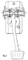
- FIG. 1 The embodiment of the invention shown in Figures 1 and 2 is a suspended brake pedal of a motor vehicle.
- a pedal lever 1 is at one of its two axial end areas provided a common step surface 2. in the area of opposite end of the pedal lever 1 is a pivot bearing hanging linkage of the pedal arranged, which consists of a Bearing block 3 and a pivot bearing pin 4 there.
- the pivot bearing pin 4 is divided, so that collectively referred to as "pivot bearing pin" 4 Construction element from two separate and coaxial to each other arranged pivot pin 6.7 there is.
- the pivot bearing pin 4 formed in two parts in this way is in bearing shells 8.9 of the bearing block 3 rotatable and axially displaceable stored. Between the two arranged parallel to each other Bearing shells 8.9 pass through the pivot bearing pin 4 bearing eyes 10,11, which are formed in the articulation area of the pedal lever 1. there penetrate the inner ends of the two-part pivot pin 4 just just the depth 12 in the bearing eyes 10,11 of the pedal lever 1 a that the realized penetration depth one during normal operation trouble-free and safe storage of the pedal lever even in rough conditions Continuous operation guaranteed.
- the depth of engagement 12 of the inner ends of the two-part pivot bearing pin 4 is in principle as short as possible, but at the same time as large as below Wear conditions required, dimensioned.
- the brake pedal arrangement shown in Fig. 2 with a solid line shows the brake pedal in normal operating position.
- FIG. 3 Another exemplary embodiment of the invention is shown in FIG. 3 shown.
- the hanging vehicle pedal shown in FIG. 3 differs from the arrangement shown in Fig. 1 in that instead of the bracket 20, each ring bearing pin 6.7 an annular Locking member 29 is associated with a plurality of locking elements 30, whose locking elements 30 engage radially in an annular groove 31 and so the Swivel axle pin 6.7 against an axial outward displacement fix under the pretension of the springs 18,19.
Landscapes
- Engineering & Computer Science (AREA)
- Physics & Mathematics (AREA)
- General Physics & Mathematics (AREA)
- Automation & Control Theory (AREA)
- Transportation (AREA)
- Mechanical Engineering (AREA)
- Mechanical Control Devices (AREA)
- Braking Elements And Transmission Devices (AREA)
- Arrangement And Mounting Of Devices That Control Transmission Of Motive Force (AREA)
Claims (7)
- Pédale de véhicule, en particulier une pédale de frein, installée de manière à pouvoir pivoter, avec une surface de commande (2) à une des deux régions d'extrémité axiale d'un levier (1) de pédale ; avec à l'autre région d'extrémité axiale du levier opposée à cette surface de commande (2), un palier de pivotement qui a un tourillon (4) logé dans le palier de pivotement et disposé perpendiculairement à l'axe du levier de la pédale et qui constitue le point d'articulation de la pédale avec le véhicule ; et avec son articulation d'actionnement ; où le tourillon (4) du palier de pivotement est divisé en deux parties dans la région de l'axe (25) du levier de la pédale où les deux parties (6, 7) du tourillon (4) du palier de pivotement sont sollicitées pour effectuer un mouvement de translation suivant l'axe du tourillon et dans les directions opposées vers l'extérieur depuis le point central de l'axe et, après la libération du levier (1) de la pédale - consécutive au désengagement d'un mécanisme de sécurité - hors des ouvertures du palier ou des manchons (8, 9) du palier, il est complètement désengagé, de sorte qu'en cas d'une force externe supérieure à une force critique s'exerçant sur l'unité de pédale et par suite du désengagement du mécanisme de sécurité, le point d'articulation du palier de pivotement peut pivoter par rapport à l'articulation d'actionnement.
- Pédale de véhicule selon la revendication 1, caractérisée : par un bloc de logement (3) de la pédale, qui est fixé sur la paroi avant (22) ou sur !e tablier avant d'un véhicule et qui est destiné au tourillon (4) du palier de pivotement en deux parties ; et par une bride (20) qui est fixée sur une partie séparée du véhicule, en particulier sur une traverse (21), qui prend en sandwich le tourillon (4) de palier de pivotement en deux parties sollicité par des ressorts, au niveau de ses têtes (16, 17) orientées axialement vers l'extérieur et qui peut effectuer un mouvement de translation dans le plan perpendiculaire à l'axe du tourillon.
- Pédale de véhicule selon la revendication 1, caractérisée par une rainure annulaire (31) aménagée dans chacune des parties (6. 7) du palier de pivotement, dans laquelle vient s'engager un dispositif d'arrêt (29), libéré par l'actionnement du mécanisme de sécurité.
- Pédale de véhicule selon la revendication 3, caractérisée par un dispositif d'arrêt (29) ayant - dans un état de fonctionnement normal - deux éléments d'arrêt (30) ou davantage qui sont engagés dans la rainure annulaire (31) et qui, en cas d'actionnement du mécanisme de sécurité, sont tous simultanément désengagés de la rainure par l'intermédiaire d'un élément de transfert (32) du dispositif d'arrêt (29).
- Pédale de véhicule selon la revendication 4, caractérisée par un convertisseur de mouvement (32) servant d'élément de transfert, qui transforme une force d'actionnement translationnelle s'exerçant tangentiellement en une force d'actionnement rotationnelle qui permet de désengager simultanément l'ensemble des éléments d'arrêt (30).
- Pédale de véhicule selon la revendication 4 ou la revendication 5, caractérisée en ce qu'un mécanisme de sécurité enregistre en un emplacement quelconque du véhicule une force dépassant une valeur de seuil et la transforme en une force mécanique d'actionnement et en ce que cette force d'actionnement agit mécaniquement sur les éléments d'arrêt (29).
- Pédale de véhicule selon la revendication 6, caractérisée par un câble sous gaine (30) pour transférer la force d'actionnement du mécanisme de sécurité à l'élément d'arrêt (29).
Applications Claiming Priority (2)
| Application Number | Priority Date | Filing Date | Title |
|---|---|---|---|
| DE19907565 | 1999-02-22 | ||
| DE19907565A DE19907565A1 (de) | 1999-02-22 | 1999-02-22 | Fahrzeugpedal |
Publications (3)
| Publication Number | Publication Date |
|---|---|
| EP1031485A2 EP1031485A2 (fr) | 2000-08-30 |
| EP1031485A3 EP1031485A3 (fr) | 2002-05-08 |
| EP1031485B1 true EP1031485B1 (fr) | 2003-09-03 |
Family
ID=7898428
Family Applications (1)
| Application Number | Title | Priority Date | Filing Date |
|---|---|---|---|
| EP00250060A Expired - Lifetime EP1031485B1 (fr) | 1999-02-22 | 2000-02-22 | Pédale de véhicule |
Country Status (2)
| Country | Link |
|---|---|
| EP (1) | EP1031485B1 (fr) |
| DE (2) | DE19907565A1 (fr) |
Families Citing this family (11)
| Publication number | Priority date | Publication date | Assignee | Title |
|---|---|---|---|---|
| DE10040270C2 (de) | 2000-08-17 | 2002-09-26 | Edscha Ag | Sicherheitseinrichtung im Pedalbereich für einen PKW |
| DE10119964B4 (de) * | 2001-04-24 | 2011-05-26 | GM Global Technology Operations LLC, ( n. d. Ges. d. Staates Delaware ), Detroit | Pedalbock |
| JP3536103B2 (ja) | 2001-06-15 | 2004-06-07 | 富士重工業株式会社 | 車両のペダル支持構造 |
| DE10161565A1 (de) * | 2001-12-14 | 2003-07-17 | Audi Ag | Pedallagerung für ein Kraftfahrzeug |
| DE10209907A1 (de) * | 2002-03-07 | 2003-09-18 | Zf Lemfoerder Metallwaren Ag | Sicherheitsvorrichtung für Kraftfahrzeuge |
| DE10227015B4 (de) * | 2002-06-17 | 2010-10-07 | ZF Lemförder GmbH | Sicherheitsvorrichtung zum Entfernen eines Bolzens, insbesondere eines Pedalbolzens bei einem Kraftfahrzeug |
| ES2276556B1 (es) * | 2004-01-20 | 2008-06-01 | Batz, S. Coop. | Pedal con mecanismo de seguridad ante colisiones frontales. |
| DE102008062868A1 (de) * | 2008-12-23 | 2010-07-01 | Volkswagen Ag | Fußhebelwerk an einem Kraftfahrzeug |
| KR101406644B1 (ko) * | 2012-08-30 | 2014-06-11 | 현대자동차주식회사 | 차량용 페달의 상해 방지장치 |
| FR3124144A1 (fr) * | 2021-06-21 | 2022-12-23 | Psa Automobiles Sa | Pedalier adapte pour proteger les pieds du conducteur en cas de choc avant sur le vehicule et vehicule comportant un tel pedalier |
| DE102022121388B4 (de) * | 2022-08-24 | 2024-08-08 | Knorr-Bremse Systeme für Nutzfahrzeuge GmbH | Lagervorrichtung, Fußbremsmodul, Kraftfahrzeug und Verfahren zum Herstellen einer Lagervorrichtung |
Family Cites Families (4)
| Publication number | Priority date | Publication date | Assignee | Title |
|---|---|---|---|---|
| DE4344386A1 (de) * | 1993-12-24 | 1995-06-29 | Opel Adam Ag | Pedalwerk für ein Fahrzeug |
| DE19501680C2 (de) * | 1995-01-20 | 1997-01-09 | Schmidt Gmbh R | Fußhebelwerk für ein Kraftfahrzeug |
| DE19631868B4 (de) * | 1996-08-07 | 2008-09-04 | Adam Opel Ag | Anordnung zur Lagerung eines Pedals |
| FR2764715B1 (fr) * | 1997-06-12 | 1999-08-27 | Peugeot | Pedalier de vehicule automobile et agencement de ce pedalier dans l'habitacle du vehicule |
-
1999
- 1999-02-22 DE DE19907565A patent/DE19907565A1/de not_active Withdrawn
-
2000
- 2000-02-22 DE DE50003493T patent/DE50003493D1/de not_active Expired - Lifetime
- 2000-02-22 EP EP00250060A patent/EP1031485B1/fr not_active Expired - Lifetime
Also Published As
| Publication number | Publication date |
|---|---|
| EP1031485A3 (fr) | 2002-05-08 |
| EP1031485A2 (fr) | 2000-08-30 |
| DE19907565A1 (de) | 2000-08-24 |
| DE50003493D1 (de) | 2003-10-09 |
Similar Documents
| Publication | Publication Date | Title |
|---|---|---|
| DE19631212C1 (de) | Fahrpedaleinheit | |
| EP1153805B1 (fr) | Dispositif de sécurité pour palier de pédales | |
| DE10243497B4 (de) | Vorrichtung zum Schutz von Personen bei einem Frontalaufprall auf ein Kraftfahrzeug | |
| EP1031485B1 (fr) | Pédale de véhicule | |
| EP2096007A1 (fr) | Dispositif de protection de piétons au capot avant d'un véhicule automobile | |
| DE102016214709A1 (de) | Lenksäule für ein Kraftfahrzeug | |
| DE3888171T2 (de) | Lenksäulenanordnung für ein kraftfahrzeug. | |
| DE3505328A1 (de) | Luftsack-rueckhaltesystem | |
| DE69934001T2 (de) | System zum Ausdrücken des Bremspedals im Falle eines Zusammenstoßes | |
| EP1202878B1 (fr) | Ensemble pour automobile | |
| EP3459828B1 (fr) | Dispositif de transfert de forces lors de la collision d'un véhicule automobile | |
| DE69506708T2 (de) | Baueinheit aus unterdruck-bremskraftverstärker und hauptbremszylinder | |
| DE1801251A1 (de) | Lenkstock fuer Kraftfahrzeuge | |
| DE10011930B4 (de) | Vorrichtung an Kraftfahrzeugen zum Absorbieren von kinetischer Energie bei einem Fahrzeugaufprall | |
| DE102011082148B4 (de) | Pedalanordnung mit einen Trennkeil aufweisender Sicherheitseinrichtung | |
| DE10032711C2 (de) | Teilbare Spurstange für Kraftfahrzeuge | |
| DE19542491C1 (de) | Sicherheitslenksäule für Kraftfahrzeuge | |
| DE102011082146B4 (de) | Pedalanordnung mit Sicherheitseinrichtung | |
| DE3908117C2 (fr) | ||
| DE102017200986A1 (de) | Pedalanordnung für ein Kraftfahrzeug mit einer Sicherheitseinrichtung | |
| EP0970879A2 (fr) | Structure de sécurité pour véhicules automobiles | |
| EP0913313B1 (fr) | Volant de direction avec un moyeu creux | |
| DE102011082154A1 (de) | Pedalanordnung mit Sicherheitseinrichtung | |
| EP1398185B1 (fr) | Attelage de remorque | |
| DE102017200989A1 (de) | Pedalanordnung für ein Kraftfahrzeug mit einer Sicherheitseinrichtung |
Legal Events
| Date | Code | Title | Description |
|---|---|---|---|
| PUAI | Public reference made under article 153(3) epc to a published international application that has entered the european phase |
Free format text: ORIGINAL CODE: 0009012 |
|
| AK | Designated contracting states |
Kind code of ref document: A2 Designated state(s): AT BE CH CY DE DK ES FI FR GB GR IE IT LI LU MC NL PT SE |
|
| AX | Request for extension of the european patent |
Free format text: AL;LT;LV;MK;RO;SI |
|
| PUAL | Search report despatched |
Free format text: ORIGINAL CODE: 0009013 |
|
| AK | Designated contracting states |
Kind code of ref document: A3 Designated state(s): AT BE CH CY DE DK ES FI FR GB GR IE IT LI LU MC NL PT SE |
|
| AX | Request for extension of the european patent |
Free format text: AL;LT;LV;MK;RO;SI |
|
| RIC1 | Information provided on ipc code assigned before grant |
Free format text: 7B 60T 7/06 A, 7G 05G 1/14 B, 7B 60R 21/09 B |
|
| RAP1 | Party data changed (applicant data changed or rights of an application transferred) |
Owner name: WOCO FRANZ-JOSEF WOLF & CO. GMBH |
|
| 17P | Request for examination filed |
Effective date: 20020717 |
|
| 17Q | First examination report despatched |
Effective date: 20021002 |
|
| AKX | Designation fees paid |
Designated state(s): DE FR |
|
| GRAH | Despatch of communication of intention to grant a patent |
Free format text: ORIGINAL CODE: EPIDOS IGRA |
|
| GRAS | Grant fee paid |
Free format text: ORIGINAL CODE: EPIDOSNIGR3 |
|
| GRAA | (expected) grant |
Free format text: ORIGINAL CODE: 0009210 |
|
| AK | Designated contracting states |
Kind code of ref document: B1 Designated state(s): DE FR |
|
| REF | Corresponds to: |
Ref document number: 50003493 Country of ref document: DE Date of ref document: 20031009 Kind code of ref document: P |
|
| REG | Reference to a national code |
Ref country code: IE Ref legal event code: FG4D Free format text: GERMAN |
|
| RAP2 | Party data changed (patent owner data changed or rights of a patent transferred) |
Owner name: WOCO INDUSTRIETECHNIK GMBH |
|
| REG | Reference to a national code |
Ref country code: IE Ref legal event code: FD4D |
|
| ET | Fr: translation filed | ||
| PLBE | No opposition filed within time limit |
Free format text: ORIGINAL CODE: 0009261 |
|
| STAA | Information on the status of an ep patent application or granted ep patent |
Free format text: STATUS: NO OPPOSITION FILED WITHIN TIME LIMIT |
|
| 26N | No opposition filed |
Effective date: 20040604 |
|
| PGFP | Annual fee paid to national office [announced via postgrant information from national office to epo] |
Ref country code: FR Payment date: 20050210 Year of fee payment: 6 |
|
| PG25 | Lapsed in a contracting state [announced via postgrant information from national office to epo] |
Ref country code: FR Free format text: LAPSE BECAUSE OF NON-PAYMENT OF DUE FEES Effective date: 20050331 |
|
| REG | Reference to a national code |
Ref country code: FR Ref legal event code: ST |
|
| PGFP | Annual fee paid to national office [announced via postgrant information from national office to epo] |
Ref country code: DE Payment date: 20120221 Year of fee payment: 13 |
|
| REG | Reference to a national code |
Ref country code: DE Ref legal event code: R119 Ref document number: 50003493 Country of ref document: DE Effective date: 20130903 |
|
| PG25 | Lapsed in a contracting state [announced via postgrant information from national office to epo] |
Ref country code: DE Free format text: LAPSE BECAUSE OF NON-PAYMENT OF DUE FEES Effective date: 20130903 |