EP1031623A2 - Verfahren zur katalytischen Spaltung von flüchtigen höheren Kohlenwasserstoffen - Google Patents
Verfahren zur katalytischen Spaltung von flüchtigen höheren Kohlenwasserstoffen Download PDFInfo
- Publication number
- EP1031623A2 EP1031623A2 EP00101992A EP00101992A EP1031623A2 EP 1031623 A2 EP1031623 A2 EP 1031623A2 EP 00101992 A EP00101992 A EP 00101992A EP 00101992 A EP00101992 A EP 00101992A EP 1031623 A2 EP1031623 A2 EP 1031623A2
- Authority
- EP
- European Patent Office
- Prior art keywords
- fluidized bed
- raw gas
- particles forming
- particles
- catalyst
- Prior art date
- Legal status (The legal status is an assumption and is not a legal conclusion. Google has not performed a legal analysis and makes no representation as to the accuracy of the status listed.)
- Granted
Links
Images

Classifications
-
- C—CHEMISTRY; METALLURGY
- C10—PETROLEUM, GAS OR COKE INDUSTRIES; TECHNICAL GASES CONTAINING CARBON MONOXIDE; FUELS; LUBRICANTS; PEAT
- C10G—CRACKING HYDROCARBON OILS; PRODUCTION OF LIQUID HYDROCARBON MIXTURES, e.g. BY DESTRUCTIVE HYDROGENATION, OLIGOMERISATION, POLYMERISATION; RECOVERY OF HYDROCARBON OILS FROM OIL-SHALE, OIL-SAND, OR GASES; REFINING MIXTURES MAINLY CONSISTING OF HYDROCARBONS; REFORMING OF NAPHTHA; MINERAL WAXES
- C10G11/00—Catalytic cracking, in the absence of hydrogen, of hydrocarbon oils
- C10G11/14—Catalytic cracking, in the absence of hydrogen, of hydrocarbon oils with preheated moving solid catalysts
- C10G11/18—Catalytic cracking, in the absence of hydrogen, of hydrocarbon oils with preheated moving solid catalysts according to the "fluidised-bed" technique
-
- C—CHEMISTRY; METALLURGY
- C10—PETROLEUM, GAS OR COKE INDUSTRIES; TECHNICAL GASES CONTAINING CARBON MONOXIDE; FUELS; LUBRICANTS; PEAT
- C10J—PRODUCTION OF PRODUCER GAS, WATER-GAS, SYNTHESIS GAS FROM SOLID CARBONACEOUS MATERIAL, OR MIXTURES CONTAINING THESE GASES; CARBURETTING AIR OR OTHER GASES
- C10J3/00—Production of combustible gases containing carbon monoxide from solid carbonaceous fuels
- C10J3/46—Gasification of granular or pulverulent flues in suspension
- C10J3/48—Apparatus; Plants
- C10J3/482—Gasifiers with stationary fluidised bed
-
- C—CHEMISTRY; METALLURGY
- C10—PETROLEUM, GAS OR COKE INDUSTRIES; TECHNICAL GASES CONTAINING CARBON MONOXIDE; FUELS; LUBRICANTS; PEAT
- C10J—PRODUCTION OF PRODUCER GAS, WATER-GAS, SYNTHESIS GAS FROM SOLID CARBONACEOUS MATERIAL, OR MIXTURES CONTAINING THESE GASES; CARBURETTING AIR OR OTHER GASES
- C10J3/00—Production of combustible gases containing carbon monoxide from solid carbonaceous fuels
- C10J3/46—Gasification of granular or pulverulent flues in suspension
- C10J3/54—Gasification of granular or pulverulent fuels by the Winkler technique, i.e. by fluidisation
-
- C—CHEMISTRY; METALLURGY
- C10—PETROLEUM, GAS OR COKE INDUSTRIES; TECHNICAL GASES CONTAINING CARBON MONOXIDE; FUELS; LUBRICANTS; PEAT
- C10K—PURIFYING OR MODIFYING THE CHEMICAL COMPOSITION OF COMBUSTIBLE GASES CONTAINING CARBON MONOXIDE
- C10K1/00—Purifying combustible gases containing carbon monoxide
- C10K1/02—Dust removal
- C10K1/024—Dust removal by filtration
-
- C—CHEMISTRY; METALLURGY
- C10—PETROLEUM, GAS OR COKE INDUSTRIES; TECHNICAL GASES CONTAINING CARBON MONOXIDE; FUELS; LUBRICANTS; PEAT
- C10K—PURIFYING OR MODIFYING THE CHEMICAL COMPOSITION OF COMBUSTIBLE GASES CONTAINING CARBON MONOXIDE
- C10K1/00—Purifying combustible gases containing carbon monoxide
- C10K1/02—Dust removal
- C10K1/026—Dust removal by centrifugal forces
-
- C—CHEMISTRY; METALLURGY
- C10—PETROLEUM, GAS OR COKE INDUSTRIES; TECHNICAL GASES CONTAINING CARBON MONOXIDE; FUELS; LUBRICANTS; PEAT
- C10K—PURIFYING OR MODIFYING THE CHEMICAL COMPOSITION OF COMBUSTIBLE GASES CONTAINING CARBON MONOXIDE
- C10K3/00—Modifying the chemical composition of combustible gases containing carbon monoxide to produce an improved fuel, e.g. one of different calorific value, which may be free from carbon monoxide
- C10K3/02—Modifying the chemical composition of combustible gases containing carbon monoxide to produce an improved fuel, e.g. one of different calorific value, which may be free from carbon monoxide by catalytic treatment
- C10K3/023—Reducing the tar content
-
- C—CHEMISTRY; METALLURGY
- C10—PETROLEUM, GAS OR COKE INDUSTRIES; TECHNICAL GASES CONTAINING CARBON MONOXIDE; FUELS; LUBRICANTS; PEAT
- C10J—PRODUCTION OF PRODUCER GAS, WATER-GAS, SYNTHESIS GAS FROM SOLID CARBONACEOUS MATERIAL, OR MIXTURES CONTAINING THESE GASES; CARBURETTING AIR OR OTHER GASES
- C10J2300/00—Details of gasification processes
- C10J2300/09—Details of the feed, e.g. feeding of spent catalyst, inert gas or halogens
- C10J2300/0913—Carbonaceous raw material
- C10J2300/0916—Biomass
- C10J2300/092—Wood, cellulose
-
- C—CHEMISTRY; METALLURGY
- C10—PETROLEUM, GAS OR COKE INDUSTRIES; TECHNICAL GASES CONTAINING CARBON MONOXIDE; FUELS; LUBRICANTS; PEAT
- C10J—PRODUCTION OF PRODUCER GAS, WATER-GAS, SYNTHESIS GAS FROM SOLID CARBONACEOUS MATERIAL, OR MIXTURES CONTAINING THESE GASES; CARBURETTING AIR OR OTHER GASES
- C10J2300/00—Details of gasification processes
- C10J2300/09—Details of the feed, e.g. feeding of spent catalyst, inert gas or halogens
- C10J2300/0983—Additives
- C10J2300/0996—Calcium-containing inorganic materials, e.g. lime
-
- C—CHEMISTRY; METALLURGY
- C10—PETROLEUM, GAS OR COKE INDUSTRIES; TECHNICAL GASES CONTAINING CARBON MONOXIDE; FUELS; LUBRICANTS; PEAT
- C10J—PRODUCTION OF PRODUCER GAS, WATER-GAS, SYNTHESIS GAS FROM SOLID CARBONACEOUS MATERIAL, OR MIXTURES CONTAINING THESE GASES; CARBURETTING AIR OR OTHER GASES
- C10J2300/00—Details of gasification processes
- C10J2300/18—Details of the gasification process, e.g. loops, autothermal operation
- C10J2300/1807—Recycle loops, e.g. gas, solids, heating medium, water
-
- C—CHEMISTRY; METALLURGY
- C10—PETROLEUM, GAS OR COKE INDUSTRIES; TECHNICAL GASES CONTAINING CARBON MONOXIDE; FUELS; LUBRICANTS; PEAT
- C10J—PRODUCTION OF PRODUCER GAS, WATER-GAS, SYNTHESIS GAS FROM SOLID CARBONACEOUS MATERIAL, OR MIXTURES CONTAINING THESE GASES; CARBURETTING AIR OR OTHER GASES
- C10J2300/00—Details of gasification processes
- C10J2300/18—Details of the gasification process, e.g. loops, autothermal operation
- C10J2300/1861—Heat exchange between at least two process streams
- C10J2300/1884—Heat exchange between at least two process streams with one stream being synthesis gas
Definitions
- the invention relates to a process for the catalytic splitting of in the gasification of carbon-containing masses, in particular biomass and sewage sludge, in a fluidized bed at temperatures from 700 to 1200 ° C, preferably 850 to 950 ° C, and a stoichiometric air factor ⁇ , based on the C. - and H content of the carbon-containing masses, from 0.28 to 0.60 volatile higher, preferably aromatic hydrocarbons of the C 6 to C 22 binding systems contained in the raw gas.
- the raw gas produced during the gasification of carbonaceous masses such as bio-waste, waste, sewage sludge, coal and the like, in a fluidized bed under lack of oxygen at temperatures from 700 to 1200 ° C. contains up to 20 g / Nm 3 higher, preferably aromatic hydrocarbons of the C 6 -bis C 22 binding systems.
- the raw gas usually has to be before gasification downstream recycling, for example in Rotary kilns, boiler systems for power generation, Current machines, piston machines or the like Be subjected to gas cleaning. Often condensing higher aromatic Hydrocarbons significantly hamper gas cleaning.
- the tar content of the raw gas is usually reduced by washing.
- the formation of aerosols that occurs makes it difficult to remove tar.
- This disadvantage tries to remedy by means of a method known from EP-B 0 310 584 for the purification of raw gas produced from a carbon-containing material by gasification.
- the raw gas generated in a first stage is subjected to a catalytic treatment in a second stage formed from a circulating fluidized bed in the presence of magnesium-calcium carbonate-containing material.
- the tar content in the raw gas is reduced to less than 500 mm / Nm 3 .
- Such a low tar content generally allows the raw gas to be cleaned by means of bag filters, since the low tar contents are absorbed by the carbon-rich dust particles still present, so that the particles remain free-flowing and the bag filters do not stick together.
- the particles forming the fluidized bed consist of at least one of the substances selected from oxides, hydroxides and carbonates of calcium, aluminum, silicon, nickel, magnesium, titanium, iron, cobalt and molybdenum, and related on the content of hydrocarbons in the raw gas, are used in stoichiometric excess.
- This measure considerably reduces the content of higher aromatic carbons, in particular the C 6 to C 22 binding systems, to contents of ⁇ 500 mg / Nm 3 .
- an "in-situ" cleavage ie a cleavage of the higher aromatic hydrocarbons, is achieved during the gasification of the carbon-containing masses.
- a special training of the invention The process can be seen in the fact that this is the fluidized bed leaving raw gas after pre-dedusting, d. H. to the separation of those from the fluidized bed Dust particles, a catalytic aftertreatment is subjected to, in which the residual contents at higher Hydrocarbons are almost completely split.
- the fluid bed is expediently left and dedusted raw gas over honeycomb catalysts or Bulk catalysts directed. They are still existing higher hydrocarbons at those there prevailing gasification temperatures catalytically in at Ambient temperatures of non-condensable gas components split. However, such catalysts can to be waived if up to 15% of the fluidized bed forming particles from a common cobalt / molybdenum and / or nickel catalyst exist.
- the Raw gas at the entrance to the catalyst is so high Airborne dust concentration, that a cleaning effect entry.
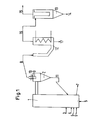
- the invention is based on one in the Drawing (Fig. 1) and a flow chart Embodiment explained in more detail.
- 2 is the Influence of different substances on the fluidized bed forming particles on the tar reduction in the raw gas as Column chart reproduced.
- the raw gas formed by the gasification and emerging from the reactor in an amount of 800 m 3 / hour still contains 0.329 g / Nm 3 of hydrocarbons which consist of 0.012 g / Nm 3 of naphthalene and 0.285 g / Nm 3 of BTX aromatics .
- the naphthalene is predominantly present in the volatile higher aromatic hydrocarbons and can be regarded as a key parameter for the splitting of the hydrocarbons, ie if the naphthalene content can be reduced to ⁇ 50 mg / Nm 3 , it can be assumed that The hydrocarbon content is so pure that it is suitable for further use in boiler systems, gas turbines, gas engines or the like without any problems.
- the raw gas is directly dedusted from the particles forming the fluidized bed in the recycle cyclone (2) downstream of the fluidized bed reactor (1) and the separated particles are fed back to the fluidized bed reactor (1) via line (11).
- the raw gas is passed over a honeycomb catalyst (10) arranged in the dip tube (9) of the recycle cyclone (2).
- the raw gas leaving the honeycomb catalyst (10) via line (8) is almost ⁇ 0.05 g / Nm 3 free of higher aromatic hydrocarbons and can thus be fed to further gas cleaning without the use of special separator stages.
- the dedusted raw gas is fed to a boiler system (12) with a heat exchanger and leaves it via line (16).
- the raw gas is cleaned in a downstream bag filter (13) and then fed to a thermal utilization via line (15).
- the fly ash and abrasion particles of the particles forming the fluidized bed still contained therein are removed from the raw gas leaving the return cyclone (2), discharged via line (17), agglomerated and returned to the fluidized bed reactor.
- the bar diagram shown in FIG. 2 shows the effect of different substances forming the fluidized bed with a grain size of 0.03 to 3 mm on higher hydrocarbons contained in the raw gas.
- the value of 100% corresponds to a hydrocarbon content of 3 to 20 g / Nm 3 .
Landscapes
- Chemical & Material Sciences (AREA)
- Engineering & Computer Science (AREA)
- Combustion & Propulsion (AREA)
- Oil, Petroleum & Natural Gas (AREA)
- Organic Chemistry (AREA)
- Chemical Kinetics & Catalysis (AREA)
- General Chemical & Material Sciences (AREA)
- Catalysts (AREA)
- Production Of Liquid Hydrocarbon Mixture For Refining Petroleum (AREA)
- Treating Waste Gases (AREA)
- Treatment Of Sludge (AREA)
Abstract
Description
Claims (11)
- Verfahren zur katalytischen Spaltung von bei der Vergasung von kohlenstoffhaltigen Massen, insbesondere Biomassen und Klärschlamm, in einer Wirbelschicht bei Temperaturen von 700 bis 1200°C, vorzugsweise 850 bis 950°C und einem stöchiometrischen Luftfaktor λ, bezogen auf den C- und H-Gehalt der kohlenstoffhaltigen Massen, von 0,28 bis 0,60 anfallenden im Rohgas enthaltenen flüchtigen, höheren, vorzugsweise aromatischen Kohlenwasserstoffen der C6- bis C22-Bindungssysteme, dadurch gekennzeichnet, daß die das Wirbelbett bildenden Partikel aus wenigstens einem der Stoffe, ausgewählt aus Oxiden, Hydroxiden und Carbonaten des Calciums, Aluminiums, Siliciums, Nickels, Magnesiums, Titans, Eisens, Cobalts und Molybdäns bestehen und, bezogen auf den Gehalt an Kohlenwasserstoffen im Rohgas, im stöchiometrischen Überschuß eingesetzt sind.
- Verfahren nach Anspruch 1, dadurch gekennzeichnet, daß die das Wirbelbett bildenden Partikel aus wenigstens einem der Stoffe, ausgewählt aus Sand, Dolomit, Zeolith, Tonerde, Laterit und nickelhaltigen Materialien bestehen.
- Verfahren nach einem der Ansprüche 1 und 2, dadurch gekennzeichnet, daß die mittlere Korngröße d50 der das Wirbelbett bildenden Partikel 0,03 bis 3,0 mm beträgt.
- Verfahren nach einem der Ansprüche 1 bis 3, dadurch gekennzeichnet, daß die Gasgeschwindigkeit 1,0 bis 7,0 m/sec beträgt.
- Verfahren nach einem der Ansprüche 1 bis 4, dadurch gekennzeichnet, daß die Gasverweilzeit 2,0 bis 15,0 sec beträgt.
- Verfahren nach einem der Ansprüche 1 bis 5, dadurch gekennzeichnet, daß aus dem vorentstaubten Rohgas die darin enthaltenen Flugasche- und Abriebteilchen der das Wirbelbett bildenden Partikel abgetrennt und in die Wirbelschicht zurückgeführt werden.
- Verfahren nach Anspruch 6, dadurch gekennzeichnet, daß die Flugasche- und Abriebteilchen nach der Abtrennung agglomeriert werden.
- Verfahren nach einem der Ansprüche 1 bis 5, dadurch gekennzeichnet, daß das die Wirbelschicht verlassende anschließend vorentstaubte Rohgas einer katalytischen Nachbehandlung unterzogen wird.
- Verfahren nach Anspruch 8, dadurch gekennzeichnet, daß das Rohgas über einen Wabenkatalysator strömt.
- Verfahren nach Anspruch 8, dadurch gekennzeichnet, daß das Rohgas über einen Schüttgutkatalysator strömt.
- Verfahren nach einem der Ansprüche 1 bis 10, dadurch gekennzeichnet, daß bis zu 15 % der die Wirbelschicht bildenden Partikel aus einem herkömmlichen Cobalt/Molybdän-Katalysator und/oder einem Nickel-Katalysator mit einer mittleren Korngröße d50 von 0,5 bis 3,0 mm bestehen.
Applications Claiming Priority (2)
| Application Number | Priority Date | Filing Date | Title |
|---|---|---|---|
| DE19907901 | 1999-02-24 | ||
| DE19907901A DE19907901C2 (de) | 1999-02-24 | 1999-02-24 | Verfahren zur katalytischen Spaltung von flüchtigen höheren Kohlenwasserstoffen |
Publications (3)
| Publication Number | Publication Date |
|---|---|
| EP1031623A2 true EP1031623A2 (de) | 2000-08-30 |
| EP1031623A3 EP1031623A3 (de) | 2002-12-18 |
| EP1031623B1 EP1031623B1 (de) | 2007-06-13 |
Family
ID=7898658
Family Applications (1)
| Application Number | Title | Priority Date | Filing Date |
|---|---|---|---|
| EP00101992A Expired - Lifetime EP1031623B1 (de) | 1999-02-24 | 2000-02-02 | Verfahren zur katalytischen Spaltung von flüchtigen höheren Kohlenwasserstoffen |
Country Status (3)
| Country | Link |
|---|---|
| EP (1) | EP1031623B1 (de) |
| AT (1) | ATE364672T1 (de) |
| DE (2) | DE19907901C2 (de) |
Cited By (5)
| Publication number | Priority date | Publication date | Assignee | Title |
|---|---|---|---|---|
| EP1142981A3 (de) * | 2000-03-23 | 2003-04-02 | Fraunhofer-Gesellschaft Zur Förderung Der Angewandten Forschung E.V. | Vorrichtung zur Stromerzeugung aus Biomasse durch Vergasung mit anschliessender katalytischer Beseitigung von Teerverbindungen aus dem Brenngas |
| WO2010019319A2 (en) | 2008-08-15 | 2010-02-18 | Conocophillips Company | Two stage entrained gasification system and process |
| EP2316280A1 (de) | 2004-01-13 | 2011-05-04 | DSM IP Assets B.V. | Enzymatische bleichung in Haushaltswaschmittel und Steinbleichungsverfahren |
| CN102827641A (zh) * | 2012-09-10 | 2012-12-19 | 庆华集团新疆和丰能源化工有限公司 | 一种煤气化热解炉 |
| CN114836225A (zh) * | 2022-04-29 | 2022-08-02 | 浙江科技学院 | 一种酸性生物炭的制备方法 |
Families Citing this family (2)
| Publication number | Priority date | Publication date | Assignee | Title |
|---|---|---|---|---|
| DE10037762B4 (de) * | 2000-03-23 | 2010-01-28 | Fraunhofer-Gesellschaft zur Förderung der angewandten Forschung e.V. | Vorrichtung zur Stromerzeugung aus Biomasse durch Vergasung mit anschließender katalytischer Beseitigung von Teerverbindungen aus dem Brenngas |
| DE102007025420B4 (de) * | 2007-05-31 | 2011-12-08 | Karlsruher Institut für Technologie | Verfahren zur Entfernung von Teersubstanzen aus Rohsynthesegasen mittels Katalysator |
Family Cites Families (7)
| Publication number | Priority date | Publication date | Assignee | Title |
|---|---|---|---|---|
| DE2532197C3 (de) * | 1975-07-18 | 1980-05-22 | Metallgesellschaft Ag, 6000 Frankfurt | Verfahren zur Erzeugung von Synthesegasen |
| GB1558996A (en) * | 1976-07-27 | 1980-01-09 | Gulf Oil Corp | Fliud bed gasifier |
| US4828581A (en) * | 1985-09-20 | 1989-05-09 | Battelle Development Corporation | Low inlet gas velocity high throughput biomass gasifier |
| SE8605211L (sv) * | 1986-12-04 | 1988-06-05 | Skf Steel Eng Ab | Sett att framstella en gas lempad for energiproduktion |
| SE459584B (sv) * | 1987-10-02 | 1989-07-17 | Studsvik Ab | Foerfarande foer foeraedling av raagas framstaelld ur ett kolhaltigt material |
| AT392079B (de) * | 1988-03-11 | 1991-01-25 | Voest Alpine Ind Anlagen | Verfahren zum druckvergasen von kohle fuer den betrieb eines kraftwerkes |
| CA2127394A1 (en) * | 1993-07-12 | 1995-01-13 | William Martin Campbell | Transport gasifier |
-
1999
- 1999-02-24 DE DE19907901A patent/DE19907901C2/de not_active Expired - Fee Related
-
2000
- 2000-02-02 AT AT00101992T patent/ATE364672T1/de active
- 2000-02-02 DE DE50014394T patent/DE50014394D1/de not_active Expired - Lifetime
- 2000-02-02 EP EP00101992A patent/EP1031623B1/de not_active Expired - Lifetime
Cited By (9)
| Publication number | Priority date | Publication date | Assignee | Title |
|---|---|---|---|---|
| EP1142981A3 (de) * | 2000-03-23 | 2003-04-02 | Fraunhofer-Gesellschaft Zur Förderung Der Angewandten Forschung E.V. | Vorrichtung zur Stromerzeugung aus Biomasse durch Vergasung mit anschliessender katalytischer Beseitigung von Teerverbindungen aus dem Brenngas |
| EP2316280A1 (de) | 2004-01-13 | 2011-05-04 | DSM IP Assets B.V. | Enzymatische bleichung in Haushaltswaschmittel und Steinbleichungsverfahren |
| WO2010019319A2 (en) | 2008-08-15 | 2010-02-18 | Conocophillips Company | Two stage entrained gasification system and process |
| WO2010019319A3 (en) * | 2008-08-15 | 2010-06-24 | Conocophillips Company | Two stage entrained gasification system and process |
| US8460410B2 (en) | 2008-08-15 | 2013-06-11 | Phillips 66 Company | Two stage entrained gasification system and process |
| US8888876B2 (en) | 2008-08-15 | 2014-11-18 | Lummus Technology Inc. | Two stage entrained gasification system and process |
| AU2009282334B2 (en) * | 2008-08-15 | 2015-11-12 | Lummus Technology Llc | Two stage entrained gasification system and process |
| CN102827641A (zh) * | 2012-09-10 | 2012-12-19 | 庆华集团新疆和丰能源化工有限公司 | 一种煤气化热解炉 |
| CN114836225A (zh) * | 2022-04-29 | 2022-08-02 | 浙江科技学院 | 一种酸性生物炭的制备方法 |
Also Published As
| Publication number | Publication date |
|---|---|
| DE19907901C2 (de) | 2001-11-29 |
| ATE364672T1 (de) | 2007-07-15 |
| DE50014394D1 (de) | 2007-07-26 |
| EP1031623A3 (de) | 2002-12-18 |
| EP1031623B1 (de) | 2007-06-13 |
| DE19907901A1 (de) | 2000-09-07 |
Similar Documents
| Publication | Publication Date | Title |
|---|---|---|
| DE69913994T2 (de) | Flash-pyrolyse in einem zyklon | |
| DE3102819C2 (de) | ||
| DE69415728T2 (de) | Teiloxydationsverfahren zur Herstellung eines Stromes von heissem gereinigten Gas | |
| EP1053291B1 (de) | Verfahren zur vergasung von organischen stoffen und stoffgemischen | |
| DE69405841T2 (de) | Energiewirksame Filtration von Synthesegas Kühl- und Waschwässern | |
| DE2640165C2 (de) | Verfahren zum Verringern des Feststoffgehaltes eines durch Partialoxidation eines kohlenstoffhaltigen Brennstoffes hergestellten Synthesegases | |
| DE69519465T2 (de) | Tranportteiloxidationsmethode | |
| EP0412587B1 (de) | Verfahren zum Reinigen von Rohbrenngas aus der Vergasung fester Brennstoffe | |
| DE2914937A1 (de) | Verfahren zum herstellen eines sauberen, praktisch hcn-freien synthesegases | |
| EP0948583B1 (de) | Verfahren zum vergasen fester brennstoffe in der zirkulierenden wirbelschicht | |
| EP1299502A1 (de) | Verfahren und vorrichtung zur pyrolyse und vergasung von stoffgemischen, die organische bestandteile enthalten | |
| DE3340204A1 (de) | Verfahren und vorrichtung zur reinigung heisser gase mit waermerueckgewinnung | |
| DE19907901C2 (de) | Verfahren zur katalytischen Spaltung von flüchtigen höheren Kohlenwasserstoffen | |
| DE60018181T2 (de) | Verfahren zur vergasung von kohlenstoffhaltigem material | |
| DE2235840A1 (de) | Verfahren zur gaserzeugung aus kohlenwasserstoffen | |
| EP3485961B1 (de) | Waschkolonne zur reinigung von gasströmen | |
| SU764616A3 (ru) | Способ получени синтез-газа | |
| DE19618213A1 (de) | Verfahren zur Erzeugung von Brenngas und Anlage zur Durchführung des Verfahrens | |
| DE3130031A1 (de) | Verfahren zur vergasung von kohle | |
| EP1399527B1 (de) | Verfahren und vorrichtung zur pyrolyse und vergasung von stoffgemischen, die organische bestandteile enthalten | |
| EP0220342A1 (de) | Verfahren zum Behandeln von wasserhaltigem Kondensat | |
| DE2657601C2 (de) | Verfahren und Vorrichtung zum Regenerieren von Fließbett-Krackkatalysatoren | |
| EP1419221B1 (de) | Verfahren zur spülung von vorkühlern einer kokerei | |
| DE2556436A1 (de) | Verfahren zum entfernen von ablagerungen an oberflaechen oder zum verhindern ihrer bildung | |
| DE4225192C2 (de) | Verfahren zur Reinigung und Wiederverwertung von in thermischen Prozessen anfallendem Kohlenstoff |
Legal Events
| Date | Code | Title | Description |
|---|---|---|---|
| PUAI | Public reference made under article 153(3) epc to a published international application that has entered the european phase |
Free format text: ORIGINAL CODE: 0009012 |
|
| AK | Designated contracting states |
Kind code of ref document: A2 Designated state(s): AT BE CH CY DE DK ES FI FR GB GR IE IT LI LU MC NL PT SE |
|
| AX | Request for extension of the european patent |
Free format text: AL;LT;LV;MK;RO;SI |
|
| RAP1 | Party data changed (applicant data changed or rights of an application transferred) |
Owner name: MG TECHNOLOGIES AG |
|
| PUAL | Search report despatched |
Free format text: ORIGINAL CODE: 0009013 |
|
| AK | Designated contracting states |
Kind code of ref document: A3 Designated state(s): AT BE CH CY DE DK ES FI FR GB GR IE IT LI LU MC NL PT SE |
|
| AX | Request for extension of the european patent |
Free format text: AL;LT;LV;MK;RO;SI |
|
| RIC1 | Information provided on ipc code assigned before grant |
Free format text: 7C 10J 3/54 A, 7C 10G 11/18 B |
|
| 17P | Request for examination filed |
Effective date: 20030618 |
|
| AKX | Designation fees paid |
Designated state(s): AT DE FR GB IT NL |
|
| 17Q | First examination report despatched |
Effective date: 20040915 |
|
| GRAP | Despatch of communication of intention to grant a patent |
Free format text: ORIGINAL CODE: EPIDOSNIGR1 |
|
| GRAC | Information related to communication of intention to grant a patent modified |
Free format text: ORIGINAL CODE: EPIDOSCIGR1 |
|
| GRAS | Grant fee paid |
Free format text: ORIGINAL CODE: EPIDOSNIGR3 |
|
| GRAA | (expected) grant |
Free format text: ORIGINAL CODE: 0009210 |
|
| AK | Designated contracting states |
Kind code of ref document: B1 Designated state(s): AT DE FR GB IT NL |
|
| RAP1 | Party data changed (applicant data changed or rights of an application transferred) |
Owner name: ENVIROTHERM GMBH |
|
| REG | Reference to a national code |
Ref country code: GB Ref legal event code: FG4D Free format text: NOT ENGLISH |
|
| GBT | Gb: translation of ep patent filed (gb section 77(6)(a)/1977) |
Effective date: 20070613 |
|
| REF | Corresponds to: |
Ref document number: 50014394 Country of ref document: DE Date of ref document: 20070726 Kind code of ref document: P |
|
| ET | Fr: translation filed | ||
| PLBE | No opposition filed within time limit |
Free format text: ORIGINAL CODE: 0009261 |
|
| STAA | Information on the status of an ep patent application or granted ep patent |
Free format text: STATUS: NO OPPOSITION FILED WITHIN TIME LIMIT |
|
| 26N | No opposition filed |
Effective date: 20080314 |
|
| PGFP | Annual fee paid to national office [announced via postgrant information from national office to epo] |
Ref country code: NL Payment date: 20140218 Year of fee payment: 15 |
|
| PGFP | Annual fee paid to national office [announced via postgrant information from national office to epo] |
Ref country code: AT Payment date: 20140212 Year of fee payment: 15 Ref country code: FR Payment date: 20140219 Year of fee payment: 15 Ref country code: IT Payment date: 20140225 Year of fee payment: 15 |
|
| PGFP | Annual fee paid to national office [announced via postgrant information from national office to epo] |
Ref country code: GB Payment date: 20140218 Year of fee payment: 15 |
|
| PGFP | Annual fee paid to national office [announced via postgrant information from national office to epo] |
Ref country code: DE Payment date: 20140403 Year of fee payment: 15 |
|
| REG | Reference to a national code |
Ref country code: DE Ref legal event code: R119 Ref document number: 50014394 Country of ref document: DE |
|
| REG | Reference to a national code |
Ref country code: NL Ref legal event code: V1 Effective date: 20150901 |
|
| PG25 | Lapsed in a contracting state [announced via postgrant information from national office to epo] |
Ref country code: NL Free format text: LAPSE BECAUSE OF NON-PAYMENT OF DUE FEES Effective date: 20150901 |
|
| REG | Reference to a national code |
Ref country code: AT Ref legal event code: MM01 Ref document number: 364672 Country of ref document: AT Kind code of ref document: T Effective date: 20150202 |
|
| GBPC | Gb: european patent ceased through non-payment of renewal fee |
Effective date: 20150202 |
|
| REG | Reference to a national code |
Ref country code: FR Ref legal event code: ST Effective date: 20151030 |
|
| PG25 | Lapsed in a contracting state [announced via postgrant information from national office to epo] |
Ref country code: AT Free format text: LAPSE BECAUSE OF NON-PAYMENT OF DUE FEES Effective date: 20150202 |
|
| PG25 | Lapsed in a contracting state [announced via postgrant information from national office to epo] |
Ref country code: IT Free format text: LAPSE BECAUSE OF NON-PAYMENT OF DUE FEES Effective date: 20150202 |
|
| PG25 | Lapsed in a contracting state [announced via postgrant information from national office to epo] |
Ref country code: GB Free format text: LAPSE BECAUSE OF NON-PAYMENT OF DUE FEES Effective date: 20150202 Ref country code: DE Free format text: LAPSE BECAUSE OF NON-PAYMENT OF DUE FEES Effective date: 20150901 |
|
| PG25 | Lapsed in a contracting state [announced via postgrant information from national office to epo] |
Ref country code: FR Free format text: LAPSE BECAUSE OF NON-PAYMENT OF DUE FEES Effective date: 20150302 |