EP1031652A2 - Dispositif de tension de la foule avec suspension progressive pour métiers à tisser - Google Patents
Dispositif de tension de la foule avec suspension progressive pour métiers à tisser Download PDFInfo
- Publication number
- EP1031652A2 EP1031652A2 EP99125153A EP99125153A EP1031652A2 EP 1031652 A2 EP1031652 A2 EP 1031652A2 EP 99125153 A EP99125153 A EP 99125153A EP 99125153 A EP99125153 A EP 99125153A EP 1031652 A2 EP1031652 A2 EP 1031652A2
- Authority
- EP
- European Patent Office
- Prior art keywords
- tension device
- warp tension
- bracket
- warp
- support elements
- Prior art date
- Legal status (The legal status is an assumption and is not a legal conclusion. Google has not performed a legal analysis and makes no representation as to the accuracy of the status listed.)
- Withdrawn
Links
Images


Classifications
-
- D—TEXTILES; PAPER
- D03—WEAVING
- D03D—WOVEN FABRICS; METHODS OF WEAVING; LOOMS
- D03D49/00—Details or constructional features not specially adapted for looms of a particular type
- D03D49/04—Control of the tension in warp or cloth
- D03D49/12—Controlling warp tension by means other than let-off mechanisms
- D03D49/14—Compensating for tension differences during shedding
Definitions
- the present invention relates to a warp tension device for a weaving loom.
- a warp tension device with a gradual-action suspension is provided.
- the healds cause the warp yarns to perform an alternating opening and closing movement of the shed for insertion of the weft yarn, a tensioning and slackening action is correspondingly exerted on the warp yarns themselves.
- These latter ones must be able to be correspondingly released or retracted so as to prevent them from being subject to excessive tension or from becoming too loose, respectively all of which adversely affects the quality of the processed fabric as well as the reliability of the loom owing to possible breakages of the yarns.
- the yarn-carrying cylinder has the possibility of performing an oscillating movement in order to assist the movement of the warp yarns and is therefore referred to as a "compensating cylinder".
- a series of resilient elements such as prestressed springs acting by means of suitable lever mechanisms.
- European patent EP-B-0,396,501 discloses a yarn-carrying cylinder which is supported on a plurality of bearing places mounted on top of brackets oscillating on a single axis.
- the oscillating brackets are mounted on a common rotating support shaft which has, arranged inside it, a torsional bar which is also connected to all the oscillating brackets. Oscillation of the brackets is integral with the rotary movement of the common support shaft, while the resilient action is ensured by the torsional bar which can be blocked in position with respect to the loom in predefined positions.
- the resilient action is adjustable by means of a suitable adjusting mechanism which determines the angular working position of the torsional bar.
- the resilient action exerted by the torsional bar on the compensating cylinder is always equivalent to that of a spring, namely is directly proportional to the angle of torsion.
- the compensating cylinder moves along a simply circular path with the axis of rotation coinciding with the central axis of the support shaft.
- the yarn-carrying cylinder is supported at several stations along the width of the loom by means of a cradle-type brackets which are free to oscillate.
- the brackets engage on a cam element, the rotation of which is opposed by a spring element.
- the resilient action is gradual since it is exerted by means of a suitable cam element.
- the compensating cylinder which is rotatable about its longitudinal axis, oscillates about the hinging axis of the cradle-type brackets and therefore also follows a simply circular path.
- the Application PCT/EP97/00701 discloses a warp tension device in which the compensating cylinder is supported on a series of fixed support rollers and is able to roll freely thereon in opposition to another series of resiliently yielding rollers. In this case also, however, the compensating cylinder follows a simply circular path.
- Fig. 1B may be difficult to realize for various reasons, including that relating to the overall dimensions of the system.
- the ideal conditions exist only for a certain instant, whereas for all the other positions assumed by the compensating cylinder, during its displacement along the arc of a circle, the spatial relationship between the force of the tension T and the rigid constraint R of the yarn carrier will vary, resulting in less favourable conditions.
- the object of the present invention is that of providing a warp tension device which always works in conditions close to the optimum ones; in particular it is desired to provide a warp tension device in which a yarn-carrying cylinder is supported so as to follow at every point a path which can be controlled as required, preferably as tangential as far as possible to the direction of the force acting thereon.
- a further object of the invention is that of providing a warp tension device which is able to perform a gradual movement, in opposition to a resilient element, so as to ensure also a gradual action while following the movement of the warp yarns.
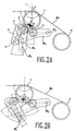
- a compensating cylinder 1 of a warp tension device is supported in a plurality of stations (at least two stations at the two ends of the yarn-carrying cylinder) arranged along the width of the loom, by means of a kinematic suspension system illustrated in detail below.
- Figs. 2A, 2B, 3 and 4 show a single suspension mechanism, but it is obvious that one is envisaged in each support station along the width of the loom.
- a first oscillating bracket S 1 pivotably mounted on a support P at G 1
- a second oscillating bracket S 2 pivotably mounted on the support P at G 2 , are provided, the support P being fixed to the weaving loom.
- the two brackets S 1 and S 2 terminate, in their upper part, with support seats, 2 and 3 respectively, which consist of rollers or bearings and on which the compensating cylinder 1 is supported.
- the compensating cylinder 1 is moreover retained on the two support seats 2 and 3 by the warp yarns Or which press on it owing to the action of the tension T.
- the two brackets S 1 and S 2 are joined to each other by means of a link rod 4 connected, via pivots 5 and 6, to the brackets S 1 and S 2 respectively.
- a link rod 4 connected, via pivots 5 and 6, to the brackets S 1 and S 2 respectively.
- the relationship between the displacements of the two support seats 2 and 3 is also predetermined and adjusted, as required, on the basis of the geometry of the kinematic mechanism.
- the two seats 2 and 3 follow two separate circular paths with angular displacements in a fixed ratio.
- a resilient element 7 acts on one of the two support brackets, for example the bracket S 1 , in opposition to a restraint integral with the loom itself.
- the various brackets S 2 which are pivotably hinged at G 2 and belong to the respective stations along the width of the loom, for example may be joined together by means of a rod which has suitable dimensions, so as to oppose in a rigid manner any torsional imbalance occurring along the width of the loom, and which in any case is rigidly connected - for example by means of a coupling of the torsional type - to the resilient opposition system, schematically shown in Fig. 4, not necessarily forming part of the compensation cylinder arrangement.
- brackets S 2 are joined to a deviating cylinder 8 which has an axis coinciding with the axis G 2 .
- the warp tension device may also comprise a deviating cylinder 8 which is arranged between the compensating cylinder 1 and the underlying warp beam U (Fig. 6) and is designed to keep as constant as possible the angle described by the warp yarn supplied by the beam U and passing over the compensating cylinder 1, i.e. the angle ⁇ between the warp yarn and a vertical axis.
- a deviating cylinder 8 which is arranged between the compensating cylinder 1 and the underlying warp beam U (Fig. 6) and is designed to keep as constant as possible the angle described by the warp yarn supplied by the beam U and passing over the compensating cylinder 1, i.e. the angle ⁇ between the warp yarn and a vertical axis.
- the extents of the arm of the force acting along the line of action of the link rod 4 with respect to the fulcrum G2 and the arm of the force pressing on the compensating cylinder 1 with respect to the same fulcrum G 2 remain unchanged, with a good degree of accuracy, during the travel of the compensating cylinder 1.
- the arm of the force transmitted by the link rod 4 is at least twice the arm of the force pressing on the compensating cylinder 1.
- Fig. 5 illustrates a possible constructional solution of the embodiment schematically described with reference to Figs. 3 and 4.
- the bracket S1 is in the form of a double lever, S 1a and S 1b respectively, which are pivotably mounted at G 1 and connected to a U-shaped link rod 4.
- the two support points of the compensating cylinder are in the form of bearings 2 and 3, while the lever S 2 is inserted between the brackets S 1a and S 1b and between the two arms of the U-shaped link rod 4.
- the fulcrums G 1 and G 2 are formed, for example, on a series of small brackets, by means of revolving and or sliding bearing seats, formed by bushes made of thermohardening material to which lubricants, such as Teflon® or molybdenum bisulphide, have been added.
- the compensation cylinder 1 no longer follows a circular path, as in the known art, but a path which may be defined, as desired, by choosing the dimensional values of the kinematic mechanism described above, thereby achieving a first object of the invention.
- the fulcrum G1 shall lies in the vicinity of the line of action of the force acting on the compensating cylinder 1; the fulcrum G2 shall be offset towards the outside (i.e. to the right in the figures) with respect to the line passing through the centre of the compensation cylinder 1 and the centre of the roller wheel 3; the locus described by the axis of the link rod 4 in its displacement interval lies approximately symmetrical with respect to the vertical.
- the amplification value of the lever mechanism is 2.5/1 or greater.
- the Applicant has found that, with the warp tension device according to the invention, the tension which is present in the warp yarns remains substantially constant also owing to the fact that the response of the suspension system is rapid and gradual.
- a first toothed wheel, rotatable about the axis G 1 is integral with the bracket S 1
- a second toothed wheel which is rotatable about the axis G 2
- a connection chain C is provided between the said two toothed wheels.
- the proper adjustment of the kinematic mechanism may be achieved, not only by replacing the kinematic components with corresponding different-sized components, but also by providing the possibility of displacing the centres of rotation G 1 and G 2 , for example by fixing said axes of rotation in the appropriate position inside slots.
- brackets may be provided, at the points where the compensation cylinder rests, with surfaces which are suitably shaped (if necessary with cam-type profiles) and coated with anti-friction material, such as bronze or Teflon® for example.
Landscapes
- Engineering & Computer Science (AREA)
- Textile Engineering (AREA)
- Looms (AREA)
Applications Claiming Priority (2)
| Application Number | Priority Date | Filing Date | Title |
|---|---|---|---|
| IT1998MI002709 IT1304112B1 (it) | 1998-12-17 | 1998-12-17 | Portafili a sospensione progressiva per telaio di tessitura |
| ITMI982709 | 1998-12-17 |
Publications (2)
| Publication Number | Publication Date |
|---|---|
| EP1031652A2 true EP1031652A2 (fr) | 2000-08-30 |
| EP1031652A3 EP1031652A3 (fr) | 2000-09-06 |
Family
ID=11381251
Family Applications (1)
| Application Number | Title | Priority Date | Filing Date |
|---|---|---|---|
| EP99125153A Withdrawn EP1031652A3 (fr) | 1998-12-17 | 1999-12-16 | Dispositif de tension de la foule avec suspension progressive pour métiers à tisser |
Country Status (2)
| Country | Link |
|---|---|
| EP (1) | EP1031652A3 (fr) |
| IT (1) | IT1304112B1 (fr) |
Cited By (1)
| Publication number | Priority date | Publication date | Assignee | Title |
|---|---|---|---|---|
| EP1445363A3 (fr) * | 2003-02-04 | 2005-01-12 | Promatech S.p.A. | Arrangement du porte-fils dans un métier à tisser |
Family Cites Families (5)
| Publication number | Priority date | Publication date | Assignee | Title |
|---|---|---|---|---|
| CH681156A5 (fr) * | 1989-05-02 | 1993-01-29 | Sulzer Ag | |
| DE4427126C2 (de) * | 1994-07-30 | 1998-09-17 | Dornier Gmbh Lindauer | Spanneinheit für die Webkette in einer Webmaschine |
| DE4427129C2 (de) * | 1994-07-30 | 1998-07-30 | Dornier Gmbh Lindauer | Spanneinheit für die Webkette einer Webmaschine |
| DE19538121C1 (de) * | 1995-10-13 | 1997-02-27 | Dornier Gmbh Lindauer | Ungesteuerte Spanneinheit für die Webkette einer Webmaschine |
| WO1997030201A1 (fr) * | 1996-02-17 | 1997-08-21 | Picanol N.V. | Dispositif pour tendre une nappe de fils de chaine dans un metier mecanique |
-
1998
- 1998-12-17 IT IT1998MI002709 patent/IT1304112B1/it active
-
1999
- 1999-12-16 EP EP99125153A patent/EP1031652A3/fr not_active Withdrawn
Cited By (1)
| Publication number | Priority date | Publication date | Assignee | Title |
|---|---|---|---|---|
| EP1445363A3 (fr) * | 2003-02-04 | 2005-01-12 | Promatech S.p.A. | Arrangement du porte-fils dans un métier à tisser |
Also Published As
| Publication number | Publication date |
|---|---|
| IT1304112B1 (it) | 2001-03-07 |
| EP1031652A3 (fr) | 2000-09-06 |
| ITMI982709A1 (it) | 2000-06-17 |
Similar Documents
| Publication | Publication Date | Title |
|---|---|---|
| CN101736497B (zh) | 具有积极松经机构的织机的送经装置 | |
| EP1878821B1 (fr) | Dispositif de soutien de cylindre d'un métier à tisser | |
| US6135163A (en) | Method and apparatus for compensating warp thread tension or elongation variations during loom shedding | |
| US4936352A (en) | Double lift open shed jacquard machine | |
| US4240471A (en) | Loom back rest mechanism | |
| US5722465A (en) | Mechanism for adjusting the terry pile height | |
| JP3586466B2 (ja) | 織機の開口装置 | |
| KR940002388A (ko) | 제직기에 사용되는 캠기구 | |
| FR2637618A1 (fr) | Dispositif pour tendre les fils de chaine dans un metier a tisser | |
| US3991793A (en) | Eccentric drive for a dobby | |
| EP1031652A2 (fr) | Dispositif de tension de la foule avec suspension progressive pour métiers à tisser | |
| US5562128A (en) | Adjustable warp tension roll support in a weaving loom | |
| KR20050086363A (ko) | 직기의 송출 장치 | |
| US4403630A (en) | Apparatus for tensioning the warp thread sheet of a loom | |
| JP2693408B2 (ja) | 織機におけるたて糸の張り装置 | |
| JP3552595B2 (ja) | 布移動方式のパイル織機の地経糸送り出しテンション装置 | |
| US6098670A (en) | Apparatus for tensioning warp threads for a weaving machine and a weaving machine with an apparatus of this kind | |
| EP0325547B1 (fr) | Système de tirage pour la commande des cadres de lisses des mécaniques d'armure du type négatif | |
| US4074730A (en) | Weft-yarn drawing-off and length-measuring apparatus of weaving loom having weft selector means | |
| US4832087A (en) | Negative dobbies of the type incorporating swinging levers | |
| EP0566506B1 (fr) | Mécanisme pour la commande alternative des couteaux dans les ratières lourdes du type à pas fermé | |
| JP2986738B2 (ja) | 織機でタオル織地を製造するためのパイルたて糸の制御装置 | |
| JP4085519B2 (ja) | 織機における経糸張力調整装置 | |
| JPH02145831A (ja) | ばね要素を有するヘッドルフレームアクチュエータ装置 | |
| JP3817932B2 (ja) | 織機における経糸張力調整装置 |
Legal Events
| Date | Code | Title | Description |
|---|---|---|---|
| PUAI | Public reference made under article 153(3) epc to a published international application that has entered the european phase |
Free format text: ORIGINAL CODE: 0009012 |
|
| PUAL | Search report despatched |
Free format text: ORIGINAL CODE: 0009013 |
|
| AK | Designated contracting states |
Kind code of ref document: A2 Designated state(s): AT BE CH CY DE DK ES FI FR GB GR IE IT LI LU MC NL PT SE |
|
| AX | Request for extension of the european patent |
Free format text: AL;LT;LV;MK;RO;SI |
|
| AK | Designated contracting states |
Kind code of ref document: A3 Designated state(s): AT BE CH CY DE DK ES FI FR GB GR IE IT LI LU MC NL PT SE |
|
| AX | Request for extension of the european patent |
Free format text: AL;LT;LV;MK;RO;SI |
|
| 17P | Request for examination filed |
Effective date: 20001016 |
|
| RAP1 | Party data changed (applicant data changed or rights of an application transferred) |
Owner name: PROMATECH S.P.A. |
|
| AKX | Designation fees paid |
Free format text: AT BE CH CY DE DK ES FI FR GB GR IE IT LI LU MC NL PT SE |
|
| STAA | Information on the status of an ep patent application or granted ep patent |
Free format text: STATUS: THE APPLICATION HAS BEEN WITHDRAWN |
|
| 18W | Application withdrawn |
Effective date: 20060525 |