EP1031686B1 - Schloss mit drückerbetätigbarer und verriegelbarer Hauptfalle - Google Patents
Schloss mit drückerbetätigbarer und verriegelbarer Hauptfalle Download PDFInfo
- Publication number
- EP1031686B1 EP1031686B1 EP00890036A EP00890036A EP1031686B1 EP 1031686 B1 EP1031686 B1 EP 1031686B1 EP 00890036 A EP00890036 A EP 00890036A EP 00890036 A EP00890036 A EP 00890036A EP 1031686 B1 EP1031686 B1 EP 1031686B1
- Authority
- EP
- European Patent Office
- Prior art keywords
- latch bolt
- auxiliary
- main
- bolt
- pin
- Prior art date
- Legal status (The legal status is an assumption and is not a legal conclusion. Google has not performed a legal analysis and makes no representation as to the accuracy of the status listed.)
- Expired - Lifetime
Links
Images

Classifications
-
- E—FIXED CONSTRUCTIONS
- E05—LOCKS; KEYS; WINDOW OR DOOR FITTINGS; SAFES
- E05B—LOCKS; ACCESSORIES THEREFOR; HANDCUFFS
- E05B63/00—Locks or fastenings with special structural characteristics
- E05B63/18—Locks or fastenings with special structural characteristics with arrangements independent of the locking mechanism for retaining the bolt or latch in the retracted position
- E05B63/20—Locks or fastenings with special structural characteristics with arrangements independent of the locking mechanism for retaining the bolt or latch in the retracted position released automatically when the wing is closed
-
- E—FIXED CONSTRUCTIONS
- E05—LOCKS; KEYS; WINDOW OR DOOR FITTINGS; SAFES
- E05B—LOCKS; ACCESSORIES THEREFOR; HANDCUFFS
- E05B55/00—Locks in which a sliding latch is used also as a locking bolt
- E05B55/12—Locks in which a sliding latch is used also as a locking bolt the bolt being secured by the operation of a hidden parallel member ; Automatic latch bolt deadlocking mechanisms, e.g. using a trigger or a feeler
-
- E—FIXED CONSTRUCTIONS
- E05—LOCKS; KEYS; WINDOW OR DOOR FITTINGS; SAFES
- E05B—LOCKS; ACCESSORIES THEREFOR; HANDCUFFS
- E05B63/00—Locks or fastenings with special structural characteristics
- E05B63/18—Locks or fastenings with special structural characteristics with arrangements independent of the locking mechanism for retaining the bolt or latch in the retracted position
- E05B63/20—Locks or fastenings with special structural characteristics with arrangements independent of the locking mechanism for retaining the bolt or latch in the retracted position released automatically when the wing is closed
- E05B2063/207—Automatic deadlocking
Definitions
- the invention relates to a lock with handle-operable and lockable main latch, which engages in a striker, and with an auxiliary latch which is inserted with the door closed by the striker and locks the main latch when inserted, the main latch in its fully extended position a locking device acted upon by the auxiliary latch and this holds in its extended position, wherein the inlet surface of the main case head of the inlet surface of the auxiliary case head is preceded for anticipatory release of the auxiliary case lock in the course of the closing process of the door, wherein in the closed position of the door with inserted auxiliary trap automatically by Spring force ausschiebbarer and is provided by a pusher and / or lock cylinder retractable latch, as well as a spring-loaded latch in the retracted position retaining tumbler, in particular a rocker , is associated with the latch, which is swung around when the auxiliary latch in the release position of the tumbler or rocker.
- a self-locking lock which has a latch and a biased by spring force in the locked position latch.
- the latch is held by a latch in the open position.
- the case holds the latch in the locked position and releases the latch only when the case is inserted and thereby the blocking of the latch is released.
- DE 37 00 891 A1 relates to a lock with a spring-loaded in the locking direction latch, which is held in the open position by a catch. The latter is triggered immediately by an auxiliary trap.
- EP 670 404 A1 discloses a self-locking lock with a spring-biased latch, a latch and an auxiliary latch that actuates a latch for holding the latch.
- a specially designed pivot lever is provided for blocking the auxiliary latch. This causes the blocking of the auxiliary trap as long as the trap is extended.
- the latch retracts and pivots the pivot lever so that the auxiliary latch can retreat. This retreat triggers the catch that has previously held back the latch.
- the bolt shoots forward and beats the front side against the lock plate in the latch pocket he finally engages.
- the invention aims to lock both the main latch when the door is closed and to release the latch as soon as it is in direct alignment with the latch pocket of the striker.
- the auxiliary latch is locked with the door open.
- a lock of the type described above in or on the shaft of the auxiliary latch a bolt or slide is slidably mounted, in the retracted position of the auxiliary latch on the one hand with one of the main latch when projecting the same trigger lever and on the other hand the tumbler, in particular rocker for the swinging kinematically aligned, so that only when in a case pocket of the closing piece projecting main latch of the latch is released to accelerate in his lock pocket of the striker.
- the pin performs a linear movement approximately parallel to the forend of the lock housing and can also be mounted on this forend.
- the pin is located on the head side on a control surface of the main catch or the main catch shaft, which raises the pin when the main catch is inserted. It may be provided between the pin and the main trap slot control, wherein a slider of the pin engages in the slot.
- auxiliary case approximately perpendicular to the insertion direction of the same in a bore a spring-mounted pin is mounted, the housing pin is in alignment with a housing fixed guide aligned housing pin opposite, wherein the housing pin of a control surface of the main trap against the pin in the auxiliary case is displaceable and this emerges from the bore in the auxiliary trap and the dividing plane between auxiliary trap and guide interspersed blocking.
- split pins are used, as they are known in tumblers in lock cylinders.
- the main catch or the shaft of the same acts as a control which displaces the pin ("housing pin") guided outside the auxiliary latch, which in turn pushes the guided in the auxiliary trap and spring-loaded pin axially and thus blocks the auxiliary trap.
- the control surface moves the housing pin when the main latch is pushed into a position in which the abutting end faces of the pins lie in the parting plane or sliding surface between the auxiliary latch and the housing-fixed guide of the housing pin.
- the locking device comprises a locking lever which engages with a control edge in a directed against the insertion direction surface, in particular to a stop of the auxiliary latch.
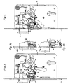
- Fig. 1 shows a lock with handle operable main latch and auxiliary latch that can be locked against incorrect operation, with the door open
- Fig. 2 the lock with the door closed
- Fig. 3 shows another embodiment of the auxiliary latch with the door open
- Fig. 3a shows a detail after Figure 4 shows a view according to Figure 3b, but including the main latch latch
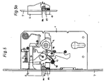
- Figure 5 shows another embodiment of the auxiliary latch latch with spring-loaded split pins when open
- Fig. 5a shows a detail when closing the door shortly after the first contact of the main latch with the striker
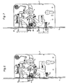
- Fig. 6 shows the complete lock according to the invention including the automatic latch with an auxiliary latch latch according to Fig. 5, with the door open and Fig. 7 the lock with the door closed with locked main latch and pushed out latch.
- a main catch 2 is mounted on and pushed out against the force of a spring 3. Via a nut 4, which has a corresponding control surface 5, the main trap 2 can be withdrawn by means of a pusher.
- an auxiliary trap 6 is spring-loaded against insertion.
- a spring is supported on the one hand on a bolt fixed to the housing and on the other hand on the inside of the auxiliary latch 5. Both cases 2 and 6 occur with the door open beyond a forend 7.
- the main trap 2 has a safety device that prevents it from being pushed in when the door is closed a plate-like burglary tool in the door gap, the main trap 2 can be pushed back. This safety device blocked with the door closed, the main case 2 in its extended position.
- the auxiliary latch 6 is scanned whether the door is closed, because the stock-side striker 37 (Fig. 2) provides a case for the intervention of the main case 2, but not such a case for the auxiliary case 6 before. The latter occupies the inserted position shown in Fig. 2 in the closed position of the door.
- Such safety devices for the main trap are known. Many of them work in such a way that the securing device and thus the blocking of the main trap 2 is activated by briefly pressing in the auxiliary latch 6. This remains activated, even if the auxiliary trap 6 exits again. Only by pressing the handle from the inside can the trap blocking be reversed. Thus, it can not be ruled out that when the door is open, someone strikes the auxiliary trap 6 and thus triggers the main trap blocking in the undesired time. However, this would mean that the next time you close the door, the blocked main case 2 does not retreat, so can not engage in the closing piece 37, but strikes it hard. As a result, lock and striker 37 are damaged.
- FIGS. 1 and 2 provide that when the door is open, the auxiliary latch 6 is locked and for the time being the main trap 2 are inserted a piece got to. It is not to be presumed that the two conditions for the activation of the lock of the main trap 2 actually occur in the intended order by chance.
- the auxiliary latch 6 has a stop 8 on which a control edge 9 of a locking lever 10 engages as soon as the main latch 2 is in its fully extended position.
- This situation shown in Fig. 1 causes the ejected auxiliary latch 6 (with the door open) can not be moved back and therefore is secured against incorrect operation. Only when the about the pivot point 11 pivotable locking lever 10 is rotated by a small angle to the right, lifts the control edge 9 from the stop 8 and the auxiliary latch 6 can be pushed back. This small rotation of the locking lever 10 is achieved by a slight pushing back of the main case 2, in which case shaft 12, a lever arm 13 of the locking lever 10 engages with some play.
- the inclined surface of the inlet slope of the main trap 2 is slightly ahead of the inclined surface of the inlet slope of the auxiliary trap 6.
- the inlet slope of the main trap 2 first with the striker in touch and is inserted first. If then a little later, the recessed inlet slope of the auxiliary latch 6 abuts against the closing piece, the already slightly hindergewichene main trap 2 has already twisted the locking lever 10 from the locking position for the auxiliary latch 6 and the auxiliary trap can recede unhindered. It has a contact surface 14, which extends after the stop 8 and engages a shoulder 15 of the locking lever 10 during insertion of the auxiliary latch 6.
- a cylindrical spring 16, each with a spring leg at the ends is pivotally mounted about a pin 17.
- the spring 16 and its legs is pivoted and these transmit a torque to a likewise pivotally mounted plate 18.
- the latter leads to the insertion of the auxiliary latch 6, mediated by the spring 16 with its two V-shaped spread legs, a Rotary movement, wherein a bearing surface 19 of this plate 18 is rotated to support under the second shoulder 20 of the locking lever 10.
- a bearing surface 19 of this plate 18 is rotated to support under the second shoulder 20 of the locking lever 10.
- Between the shoulders 15 and 20 is the fulcrum of the locking lever 10. If this is supported on both sides of its fulcrum by contact surfaces, then rotation of the locking lever 10 is excluded.
- the engaging in the case shaft 12 of the main case 2 lever arm 13 thus blocks the main case 2, so that it is secured against tampering and in particular against the attempt of insertion from the outside.
- FIGS. 3, 3a, 3b and 4 A completely different solution for a locking device which acts on the auxiliary latch 6 is shown in FIGS. 3, 3a, 3b and 4.
- FIG. A pin 30 is slidably mounted in a housing-fixed guide 31 against the force of a spring 32 along the cuff 7. The head of the pin 30 abuts against a control surface 33 of the main latch 2 and the main latch shaft 12, respectively. The pin 30 passes through the housing-fixed guide 31 and thereafter a slot-like clearance 34 in the auxiliary case 6. In the exit region of the pin 30, a collar 35 is attached to the pin 30, which according to FIG. 3, a step 36 on the auxiliary latch 6 directly opposite.
- both the main trap 2 and the auxiliary trap 6 are pushed out when the door is open.
- the control surface 33 holds the collar 35 in the insertion level of the auxiliary latch 6 at the level of the step 36.
- the auxiliary latch 6 can not be inserted.
- the slightly advanced inlet surface of the main trap 2 is pushed back by an edge of a closing piece 37, the pin 30 runs on a ramp of the control surface 33.
- the pin 30 is moved linearly against the force of the spring 32 and the collar 35 lifts off from the auxiliary latch 6, so that the stage 36 is now released. In the course of the further closing movement of the door and the auxiliary latch 6 can be inserted.
- the main trap 2 can not be pushed back. Only when due to handle operation, the plate 18 by a control edge of the nut 4 again in the direction of their 3 is turned back (game of the lever arm 13 'this locking lever 10' between the contact surfaces in the main traction shank 12), the main trap 2 can be retracted and the door can be opened.
- the auxiliary latch 6 springs out and is immediately blocked by the pin 30 or its collar 35 according to FIG. 3. The main trap 6 can therefore be inserted either accidentally (unintentionally) or intentionally with the door open.
- FIG. 5 A further alternative for a locking device is shown in FIG. 5.
- a housing-fixed guide 31 which continues in a bore in the auxiliary latch 6, a housing pin 38 and an auxiliary latch pin 39 are displaceably mounted against spring force.
- the housing pin 38 is located at one end to a control surface 33 of the main latch 2 and at the other end to the auxiliary latch pin 39 at.
- the auxiliary catch pin 39 is located with the door open in the dividing plane between the housing fixed guide 31 and auxiliary latch 6, whereby the auxiliary latch 6 is blocked.
- the door is open, it can not lead to malfunctions, for example as a result of unintentional insertion of the auxiliary latch 6.
- Fig. 5a shows this situation.
- the pin pair 38 and 39 is pushed back by the ramp in the control surface 33, and just so far that the contact surface between the pins 38 and 39 is located in the aforementioned division plane.
- the blocking of the auxiliary trap 6 is released.
- the auxiliary latch 6 can be pushed in by the closing piece in its entirety.
- FIG. 6 the locking device according to Fig. 5 and 5a in connection with the entire lock construction is shown by way of example.
- it could also be another locking device for the auxiliary trap 6 in their place.
- FIG. 6 the auxiliary trap blocking is shown analogously to FIG. With the door closed and pushed out the main trap 2, it can be seen that the pitched pins 38, 39 are shifted in the division plane to each other, since the auxiliary latch 6 is pushed back by the closing piece 37. Thus, as explained in connection with FIGS. 2 and 4, the main case 2 is locked.
- FIG. 6 In the course of closing the door, starting from Fig. 6 is the time-delayed release of the spring-loaded latch 21.
- This latch 21 is biased by a spring 22 in the direction of its blocking position, however, as shown in FIG. 6 by a rocker 23 (two-armed lever) in the retained retracted position.
- This rocker 23 is disposed below the auxiliary latch 6 and rotatably mounted about a pin fixed to the housing.
- a lever arm of the rocker 23 has a nose which engages in a recess of the bolt 21 and abuts there against a stop surface. When the rocker 23 swings, the nose lifts off the abutment surface; the latch 21 is released and jumps out under the action of the spring 22 via the forend 7 from the lock housing 1 out.
- a release lever 24 is provided in the form of a two-armed angle lever, on the one hand by a stop surface on the main catch shaft 12th is taken in the ejection movement.
- This release lever 24 sets the horizontal Ausschubterrorism the main case 2 in a vertical movement of a shaft mounted in the auxiliary case 6 bolt 25.
- the bolt 25 makes the horizontal movement of the auxiliary latch 6 so with. If the door is open (FIG. 6), then the bolt 25 has moved out of the kinematic connection to the release lever 24. But if the door is closed is (Fig. 7), then the pin axis is exactly aligned with the triggering edge of the trigger lever 24 and the pin 25 performs a thrusting movement, which is directed against the control edge of the rocker 23. Thus, a torque acts on the rocker 23; the rocker 23 pivots and her nose releases the latch 21, which now vorschnellt.
- the auxiliary latching shank may be provided with a guide, e.g. a dovetail on a flat side, be formed, in which a slider perpendicular to the direction of movement of the auxiliary latch 6 slides.
- Bolt 25 or slide are biased by a spring (not shown) so that they project beyond the auxiliary latch 6 and its shaft (Fig. 6).
- This spring may e.g. be provided on the axis of the rocker 23 and bias the rocker 23 in a clockwise direction.
- the above mechanism only comes into effect when the door is closed, the auxiliary latch 6 pushed back from the striker 37 and the main latch 2 is already on the way to the main case pocket of the striker 37 after being pushed back by the striker 37.
- the delayed lashing of the bolt 21 ensures that the latch 21 does not hit against the front side of the closing piece 37 and there along schleips until the door is completely closed, the latch can finally engage in the latch pocket. Rather, the latch 21 according to the invention is triggered only when its movement into the blocking position is no longer in the way.
- the plate 18 is part of a lever which is actuated by the nut 4 via a control surface. If, starting from Fig. 7, the nut 4 is rotated by a pusher clockwise by about 45 °, then pivots the plate 18 and provided in continuation of the plate 18 two-armed lever in the counterclockwise direction and pulls the latch 21 a.
- the operation can also be done by a lock cylinder in a known manner. A change, for example, the connection to the main case 2 ago while the closing lug of the lock cylinder causes the withdrawal of the bolt 21.
Landscapes
- Engineering & Computer Science (AREA)
- Structural Engineering (AREA)
- Lock And Its Accessories (AREA)
- Details Of Spanners, Wrenches, And Screw Drivers And Accessories (AREA)
- Telephone Function (AREA)
- Purses, Travelling Bags, Baskets, Or Suitcases (AREA)
- Toys (AREA)
- Steering Devices For Bicycles And Motorcycles (AREA)
- Breakers (AREA)
Description
- Die Erfindung betrifft ein Schloss mit drückerbetätigbarer und verriegelbarer Hauptfalle, die in ein Schließstück einrastet, sowie mit einer Hilfsfalle, die bei geschlossener Tür durch das Schließstück eingeschoben ist und die beim Einschieben die Hauptfalle verriegelt, wobei die Hauptfalle in ihrer zur Gänze ausgeschobenen Position eine Sperreinrichtung beaufschlagt, die an der Hilfsfalle angreift und diese in ihrer ausgeschobenen Position festhält, wobei die Einlauffläche des Hauptfallenkopfes der Einlauffläche des Hilfsfallenkopfes zur vorauseilenden Freigabe der Hilfsfallensperre im Zuge des Schließvorganges der Tür vorgelagert ist, wobei ein in der Geschlossenstellung der Tür bei eingeschobener Hilfsfalle selbsttätig durch Federkraft ausschiebbarer und durch einen Drücker und bzw. oder Schließzylinder zurückziehbarer Riegel vorgesehen ist, sowie eine den federvorgespannten Riegel in der zurückgezogenen Stellung festhaltende Zuhaltung, wie insbesondere eine Wippe, dem Riegel zugeordnet ist, die bei eingeschobener Hilfsfalle in die Freigabestellung der Zuhaltung bzw. Wippe umschwenkbar ist.
- In vielen Fällen ist es wünschenswert, eine Falle eines selbstverriegelnden Schlosses in der Geschlossenstellung einer Türe bei ausgeschobenem Riegel zusätzlich zu verriegeln, sodass die Falle, etwa durch Einschieben eines Plättchens in den Türspalt, nicht zurückgeschoben werden kann. Wenn es nämlich gelingt, beispielsweise eine Credit-Card in der Höhe einer nicht verriegelbaren Falle in den Türspalt tief einzuschieben, dann stößt die Stirnkante dieser als Einbruchswerkzeug missbrauchten Credit-Card gegen die Schrägfläche (Einlaufschräge) der Falle und drückt diese zurück. Auf diese Weise könnte die durch eine ausgeschobene Falle bewirkte zusätzliche Sperre einer Tür, die nur von innen drückerbetätigbar ist, umgangen werden, sodass nur noch der Riegel die Tür versperrt hält.
- Aus der DE 215 150 B ist ein selbstverriegelndes Schloss bekannt, das eine Falle und einen durch Federkraft in der Sperrstellung vorgespannten Riegel aufweist. Der Riegel wird durch eine Klinke in der Offenstellung festgehalten. Um zu verhindern, dass der Riegel bei offener Tür durch Fehlbedienung unbeabsichtigt herausspringt, hält die Falle die Klinke in der Sperrstellung fest und gibt die Klinke erst frei, wenn die Falle eingeschoben und dadurch die Blockierung der Klinke aufgehoben ist. Die DE 37 00 891 A1 betrifft ein Schloss mit einem in Verriegelungsrichtung federbelasteten Riegel, der in der Öffnungsstellung durch eine Raste festgehalten wird. Letztere wird unmittelbar durch eine Hilfsfalle ausgelöst. Schließlich geht aus der EP 670 404 A1 ein selbstverriegelndes Schloss mit einem federvorgespannten Riegel, einer Falle und einer Hilfsfalle hervor, die eine Raste zum Festhalten des Riegels betätigt. Ein besonders ausgebildeter Schwenkhebel ist zur Blockierung der Hilfsfalle vorgesehen. Dieser bewirkt die Blockierung der Hilfsfalle, so lange die Falle ausgefahren ist. Sobald die Türe geschlossen wird, fährt die Falle ein und verschwenkt den Schwenkhebel so, dass die Hilfsfalle zurückweichen kann. Dieses Zurückweichen löst die Raste aus, die den Riegel bisher zurückgehalten hat. Der Riegel schnellt vor und schlägt stirnseitig gegen das Schlossblech in dessen Riegeltasche er schließlich einrastet.
- Die Erfindung zielt darauf ab, sowohl die Hauptfalle zu verriegeln, wenn die Tür geschlossen ist, als auch den Riegel auszulösen, sobald diesem die Riegeltasche des Schließstückes unmittelbar fluchtend gegenübersteht. Um Fehlbedienungen zu vermeiden ist die Hilfsfalle bei offener Tür arretiert. Dieses Ziel wird mit einem Schloss der eingangs beschriebenen Art erreicht, wobei erfindungsgemäß in oder an dem Schaft der Hilfsfalle ein Bolzen oder Schieber verschiebbar gelagert ist, der in der eingeschobenen Stellung der Hilfsfalle einerseits mit einem von der Hauptfalle beim Vorspringen derselben betätigbaren Auslösehebel und anderseits mit der Zuhaltung, insbesondere Wippe zu deren Umschwenken kinematisch fluchtet, sodass erst bei in eine Fallentasche des Schließstückes vorspringender Hauptfalle der Riegel zum Vorschnellen in seine Riegeltasche des Schließstückes freigegeben ist. Es wird damit einerseits eine Fehlfunktion des Riegels vermieden und die Auslösung des Riegels nicht nur von der Position der Hilfsfalle abhängig gemacht, sondern von der in die Hauptfallentasche des Schließstückes tatsächlich vorspringenden Hauptfalle. Somit wird der Riegel nicht schon beim Einschieben der Hilfsfalle oder der Hauptfalle freigegeben, sondern erst dann, wenn die beiden Kriterien der eingeschobenen Hilfsfalle und der bereits wieder vorspringenden Hauptfalle erfüllt sind.
- Es ist zweckmäßig, wenn als Sperreinrichtung zwischen Hauptfalle und Hilfsfalle mindestens ein von der Hauptfalle gesteuerter, axial verschiebbarer Stift vorgesehen ist, der bei Einschieben der Hauptfalle aus einer Sperrstellung der Hilfsfalle verschiebbar ist und beispielsweise von einer Anlagefläche an der Hilfsfalle abhebt. Der Stift führt eine Linearbewegung etwa parallel zum Stulp des Schlossgehäuses aus und kann auch an diesem Stulp gelagert sein. Der Stift liegt in einer bevorzugten Ausführungsform kopfseitig an einer Steuerfläche der Hauptfalle bzw. des Hauptfallenschaftes an, die den Stift beim Einschieben der Hauptfalle anhebt. Es kann zwischen Stift und Hauptfalle eine Schlitzsteuerung vorgesehen sein, wobei ein Gleitstück des Stiftes in den Schlitz eingreift. Damit ist der Stift zwangsgesteuert. Eine weitere mit Vorteil realisierte Ausführungsform sieht vor, dass in der Hilfsfalle etwa senkrecht zur Einschubrichtung derselben in einer Bohrung ein gefederter Stift gelagert ist, dem bei ausgeschobener Hauptfalle ein in einer gehäusefesten Führung gelagerter Gehäusestift fluchtend gegenüberliegt, wobei der Gehäusestift von einer Steuerfläche der Hauptfalle gegen den Stift in der Hilfsfalle verschiebbar ist und dieser aus der Bohrung in der Hilfsfalle austritt und die Teilungsebene zwischen Hilfsfalle und Führung blockierend durchsetzt. Somit werden geteilte Stifte verwendet, wie diese bei Zuhaltungen in Schließzylindern bekannt sind. Die Hauptfalle bzw. der Schaft derselben wirkt als Steuerelement, welches den außerhalb der Hilfsfalle geführten Stift ("Gehäusestift") verschiebt, der seinerseits den in der Hilfsfalle geführten und gefederten Stift axial zurückdrängt und damit die Hilfsfalle blockiert. Zur Freigabe der Hilfsfalle ist es zweckmäßig, wenn die Steuerfläche den Gehäusestift bei eingeschobener Hauptfalle in eine Position verschiebt, in der die aneinanderliegenden Stirnflächen der Stifte in der Teilungsebene bzw. Gleitfläche zwischen Hilfsfalle und der gehäusefesten Führung des Gehäusestiftes liegen.
- Gemäß einer weiteren Ausführung umfasst die Sperreinrichtung einen Sperrhebel, der mit einer Steuerkante an einer gegen die Einschubrichtung gerichteten Fläche, insbesondere an einen Anschlag der Hilfsfalle angreift.
- Ausführungsbeispiele zum Verständnis des Erfindungsgegenstandes sind in den Zeichnungen dargestellt, wobei die Schlösser in den Figuren 1-5 ohne den erfindungsgemäßen Bolzen oder Schrieber dargestellt sind.
- Fig. 1 zeigt ein Schloss mit drückerbetätigbarer Hauptfalle und mit Hilfsfalle, die gegen Fehlbedienung verriegelbar ist, bei offener Tür, Fig. 2 das Schloss bei geschlossener Tür, Fig. 3 eine andere Ausführungsform der Hilfsfallenverriegelung bei offener Tür, Fig. 3a ein Detail nach der ersten Berührung der Hauptfalle mit dem Schließstück, Fig. 3b bei geschlossener Tür sowie ein Detail von unten, Fig. 4 eine Ansicht gemäß Fig. 3b jedoch einschließlich der Hauptfallenverriegelung, Fig. 5 eine weitere Ausführungsform der Hilfsfallenverriegelung mit gefederten, geteilten Stiften bei offener Tür, Fig. 5a ein Detail beim Schließen der Tür kurz nach der ersten Berührung der Hauptfalle mit dem Schließstück, Fig. 6 das vollständige Schloss gemäß der Erfindung einschließlich des selbsttätigen Riegels mit einer Hilfsfallenverriegelung nach Fig. 5, bei offener Tür und Fig. 7 das Schloss bei geschlossener Tür mit verriegelter Hauptfalle und ausgeschobenem Riegel.
- In einem Schlossgehäuse 1 ist gemäß Fig. 1 und 2 eine Hauptfalle 2 gegen die Kraft einer Feder 3 ein- und ausschiebbar gelagert. Über eine Nuss 4, die eine entsprechende Steuerfläche 5 aufweist, kann die Hauptfalle 2 mittels eines Drückers zurückgezogen werden. Unterhalb der Hauptfalle 2 ist eine Hilfsfalle 6 gegen Einschieben federbelastet gelagert. Dazu stützt sich eine Feder einerseits an einem gehäusefesten Bolzen und anderseits im Inneren an der Hilfsfalle 5 ab. Beide Fallen 2 und 6 treten bei offen stehender Tür über einen Stulp 7 hinaus.
- Die Hauptfalle 2 verfügt über eine Sicherungseinrichtung, die verhindert, dass bei geschlossener Tür durch Einschieben eines plattenähnlichen Einbruchswerkzeuges in den Türspalt die Hauptfalle 2 zurückgedrängt werden kann. Diese Sicherungseinrichtung blockiert bei geschlossener Tür die Hauptfalle 2 in ihrer ausgeschobenen Stellung. Über die Hilfsfalle 6 wird abgetastet, ob die Türe geschlossen ist, denn das stockseitige Schließstück 37 (Fig. 2) sieht zwar eine Fallentasche für das Eingreifen der Hauptfalle 2, nicht aber eine solche Fallentasche für die Hilfsfalle 6 vor. Letztere nimmt in der Geschlossenstellung der Tür die in Fig. 2 dargestellte eingeschobene Lage ein.
- Solche Sicherungseinrichtungen für die Hauptfalle sind bekannt. Viele davon arbeiten derart, dass schon durch kurzes Eindrücken der Hilfsfalle 6 die Sicherungseinrichtung und damit die Blockierung der Hauptfalle 2 aktiviert wird. Diese bleibt aktiviert, auch wenn die Hilfsfalle 6 wieder austritt. Erst durch Drückerbetätigung von innen kann die Fallenblockierung rückgängig gemacht werden. Somit ist nicht auszuschließen, dass bei geöffneter Tür jemand an der Hilfsfalle 6 anstreift und damit die Hauptfallenblockierung im unerwünschten Zeitpunkt auslöst. Dies hätte aber zur Folge, dass beim nächsten Schließen der Tür die blockierte Hauptfalle 2 nicht zurückweichen, also in das Schließstück 37 nicht einrasten kann, sondern an diesem hart anschlägt. Dadurch werden Schloss und Schließstück 37 beschädigt.
- Um zu verhindern, dass durch ein bloßes kurzes Einschieben der Hilfsfalle 6 die obige Wirkung bereits eintritt sieht die Ausführung nach Fig. 1 und 2 vor, dass bei offener Tür die Hilfsfalle 6 gesperrt ist und zu deren Freigabe vorerst die Hauptfalle 2 ein Stück eingeschoben werden muss. Es ist nicht anzunehmen, dass die beiden Bedingungen für die Aktivierung der Verriegelung der Hauptfalle 2 tatsächlich in der vorgesehenen Reihenfolge durch Zufall eintreten.
- Die Hilfsfalle 6 verfügt bei einer Ausführungsform über einen Anschlag 8, an dem eine Steuerkante 9 eines Sperrhebels 10 angreift, sobald sich die Hauptfalle 2 in ihrer zur Gänze ausgeschobenen Stellung befindet. Diese in Fig. 1 dargestellte Situation führt dazu, dass die ausgeschobene Hilfsfalle 6 (bei offener Tür) nicht zurückbewegt werden kann und daher gegen eine Fehlbedienung gesichert ist. Erst wenn der um dem Drehpunkt 11 schwenkbare Sperrhebel 10 um einen kleinen Winkel nach rechts verdreht wird, hebt die Steuerkante 9 vom Anschlag 8 ab und die Hilfsfalle 6 kann zurückgeschoben werden. Diese kleine Verdrehung des Sperrhebels 10 wird durch ein geringfügiges Zurückschieben der Hauptfalle 2 erreicht, in deren Fallenschaft 12 ein Hebelsarm 13 des Sperrhebels 10 mit etwas Spiel eingreift. Um beim normalen Schließen der Tür die Hilfsfallensperre auszuheben und dann in weitere Folge die Hauptfallensperre bei geschlossener Tür zu aktivieren, liegt die Schrägfläche der Einlaufschräge der Hauptfalle 2 etwas vor der Schrägfläche der Einlaufschräge der Hilfsfalle 6. Beim Schließen der Tür kommt also die Einlaufschräge der Hauptfalle 2 zuerst mit dem Schließstück in Berührung und wird zuerst eingeschoben. Wenn dann ein wenig später auch die zurückversetzte Einlaufschräge der Hilfsfalle 6 gegen das Schließstück stoßt, hat die bereits etwas zurückgewichene Hauptfalle 2 den Sperrhebel 10 schon aus der Sperrstellung für die Hilfsfalle 6 verdreht und die Hilfsfalle kann unbehindert zurückweichen. Sie verfügt über eine Anlagefläche 14, die im Anschluss an den Anschlag 8 verläuft und beim Einschieben der Hilfsfalle 6 eine Schulter 15 des Sperrhebels 10 untergreift. Eine zylindrische Feder 16 mit jeweils einem Federschenkel an den Enden ist um einen Zapfen 17 schwenkbar gelagert. Beim Einschieben der Hilfsfalle 6 wird die Feder 16 bzw. deren Schenkel verschwenkt und diese übertragen ein Drehmoment auf eine ebenfalls schwenkbar gelagerte Platte 18. Letztere führt beim Einschieben der Hilfsfalle 6, vermittelt durch die Feder 16 mit ihren beiden V-förmig gespreizten Schenkeln, eine Drehbewegung aus, wobei eine Anlagefläche 19 dieser Platte 18 zur Abstützung unter die zweite Schulter 20 des Sperrhebels 10 gedreht wird. Zwischen den Schultern 15 und 20 liegt der Drehpunkt des Sperrhebels 10. Wenn dieser beiderseits seines Drehpunktes durch Anlageflächen unterstützt ist, dann ist ein Verdrehen des Sperrhebels 10 ausgeschlossen. Der in den Fallenschaft 12 der Hauptfalle 2 eingreifende Hebelsarm 13 blockiert also die Hauptfalle 2, sodass sie gegen ein Manipulieren und insbesondere gegen den Versuch eines Einschiebens von außen gesichert ist.
- Eine völlig andere Lösung für eine Sperreinrichtung, die an der Hilfsfalle 6 angreift, ist in den Fig. 3, 3a, 3b und 4 dargestellt. Ein Stift 30 ist in einer gehäusefesten Führung 31 gegen die Kraft einer Feder 32 längs des Stulps 7 verschiebbar gelagert. Der Kopf des Stiftes 30 liegt an einer Steuerfläche 33 der Hauptfalle 2 bzw. des Hauptfallenschaftes 12 an. Der Stift 30 durchgreift die gehäusefeste Führung 31 und im Anschluss daran einen langlochähnlichen Freiraum 34 in der Hilfsfalle 6. Im Austrittsbereich des Stiftes 30 ist am Stift 30 ein Kragen 35 angesetzt, dem gemäß Fig. 3 eine Stufe 36 an der Hilfsfalle 6 unmittelbar gegenüberliegt.
- Gemäß Fig. 3 ist bei offener Tür sowohl Hauptfalle 2 als auch Hilfsfalle 6 ausgeschoben. Die Steuerfläche 33 hält den Kragen 35 in der Einschubebene der Hilfsfalle 6 in der Höhe der Stufe 36. Dadurch kann die Hilfsfalle 6 nicht eingeschoben werden. Erst wenn gemäß Fig. 3a beim Schließen der Tür die etwas vorgeschobene Einlauffläche der Hauptfalle 2 durch eine Kante eines Schließstückes 37 zurückgedrängt wird, läuft der Stift 30 auf eine Rampe der Steuerfläche 33 auf. Der Stift 30 wird gegen die Kraft der Feder 32 linear verschoben und der Kragen 35 hebt von der Hilfsfalle 6 ab, sodass die Stufe 36 nun freigestellt ist. Im Zuge der weiteren Schließbewegung der Tür kann auch die Hilfsfalle 6 eingeschoben werden. Sobald die Hauptfalle 2 in die Fallentasche des Schließstückes 37 vorschnellt, legt sich der Kragen 35 des Stiftes 30 an die Randbereiche des langlochähnlichen Freiraumes 34 an. Die Hilfsfalle 6 kann trotz ihrer Federvorspannung nicht aus dem Schlossgehäuse austauchen, weil die Hilfsfalle 6 stirnseitig am Schließstück 37 anliegt (Fig. 3b). In Fig. 3b ist der Freiraum 34 mit dem Stift 30 bzw. dessen Kragen 35 als weiteres Detail zusätzlich in Untersicht dargestellt. Die Hauptfalle ist in dieser Lage verriegelt, wie Fig. 4 zeigt. Der Sperrhebel 10 liegt nämlich mit seiner Schulter 20 an der Anlagefläche 19 der Platte 18 an. Letztere wurde gegenüber ihrer Position in Fig. 3 infolge des Einschiebens der Hilfsfalle 6 von der Feder 16 in die Position nach Fig. 4 verschwenkt. Damit kann die Hauptfalle 2 nicht zurückgedrückt werden. Erst wenn infolge Drückerbetätigung die Platte 18 durch eine Steuerkante der Nuss 4 wieder in Richtung ihrer Lage nach Fig. 3 zurückgedreht ist (Spiel des Hebelsarmes 13'dies Sperrhebels 10' zwischen den Anlageflächen im Hauptfallenschaft 12), kann die Hauptfalle 2 eingezogen und die Tür geöffnet werden. Dabei springt die Hilfsfalle 6 heraus und wird sogleich durch den Stift 30 bzw. dessen Kragen 35 gemäß Fig. 3 blockiert. Die Hauptfalle 6 kann daher weder zufällig (unbeabsichtigt) noch mit Absicht bei offener Tür eingeschoben werden.
- Eine weitere Alternative für eine Sperreinrichtung zeigt Fig. 5. Parallel zum Stulp 7 sind in einer gehäusefesten Führung 31, die sich in einer Bohrung in der Hilfsfalle 6 fortsetzt, ein Gehäusestift 38 und ein Hilfsfallenstift 39 gegen Federkraft verschiebbar gelagert. Der Gehäusestift 38 liegt mit einem Ende an einer Steuerfläche 33 der Hauptfalle 2 und mit dem anderen Ende an dem Hilfsfallenstift 39 an. Wie Fig. 5 zeigt, liegt der Hilfsfallenstift 39 bei offener Tür in der Teilungsebene zwischen gehäusefester Führung 31 und Hilfsfalle 6, wodurch die Hilfsfalle 6 blockiert ist. Dadurch kann es bei offener Tür nicht zu Fehlfunktionen etwa infolge eines unbeabsichtigten Einschiebens der Hilfsfalle 6 können.
- Erst im Zuge des Schließvorganges der Tür wird die Hauptfalle 2 infolge der etwas weiter vorne liegenden Einlaufschrägfläche als jene der Hilfsfalle durch eine Kante des Schließstückes innerhalb des Spiels der an sich blockierten Hauptfalle 2 zurückgeschoben, bevor diese Kante noch die Hilfsfalle 6 erreicht (analog Fig. 3a). Die Fig. 5a zeigt diese Situation. Das Stiftpaar 38 und 39 wird durch die Rampe in der Steuerfläche 33 zurückgedrängt und zwar genau so weit, dass die Berührungsfläche zwischen den Stiften 38 und 39 in der vorgenannten Teilungsebene liegt. Damit ist die Blockierung der Hilfsfalle 6 aufgehoben. Beim weiteren Schließvorgang kann die Hilfsfalle 6 durch das Schließstück zur Gänze eingeschoben werden.
- In den Fig. 6 und 7 ist die Sperreinrichtung nach Fig. 5 bzw. 5a in Verbindung mit der gesamten Schlosskonstruktion beispielhaft dargestellt. Es könnte natürlich auch eine andere Sperreinrichtung für die Hilfsfalle 6 an deren Stelle treten. Was die Fig. 6 betrifft, so ist die Hilfsfallenblockierung analog zu Fig. 5 dargestellt. Bei geschlossener Tür und ausgeschobener Hauptfalle 2 erkennt man, dass die auf Teilung gebrachten Stifte 38, 39 in der Teilungsebene zueinander verschoben sind, da ja die Hilfsfalle 6 durch das Schließstück 37 zurückgeschoben ist. Damit ist, wie im Zusammenhang mit Fig. 2 und 4 erläutert, die Hauptfalle 2 verriegelt.
- Im Zuge des Schließens der Tür, ausgehend von Fig. 6 erfolgt das zeitverschobene Auslösen des federbelasteten Riegels 21. Dieser Riegel 21 wird von einer Feder 22 in Richtung seiner Sperrstellung vorgespannt, jedoch gemäß Fig. 6 von einer Wippe 23 (zweiarmiger Hebel) in der eingeschobenen Stellung zurückgehalten. Diese Wippe 23 ist unterhalb der Hilfsfalle 6 angeordnet und um einen gehäusefesten Zapfen drehbar gelagert. Ein Hebelsarm der Wippe 23 verfügt über eine Nase, die in eine Ausnehmung des Riegels 21 eingreift und dort an einer Anschlagfläche anliegt. Wenn die Wippe 23 umschwenkt, dann hebt die Nase von der Anschlagfläche ab; der Riegel 21 ist freigegeben und schnellt unter der Wirkung der Feder 22 über den Stulp 7 aus dem Schlossgehäuse 1 heraus. Dies soll jedoch nur bei zuverlässig geschlossener Tür geschehen und darf nicht unbeabsichtigt oder bewusst missbräuchlich durch Auslösen über die Hilfsfalle 6 erfolgen. Um dies sicherzustellen wird der Riegel 21 nicht schon beim Eindrücken der Hilfsfalle 6 durch das Schließstück 37, sondern durch die Hauptfalle 2 freigegeben - und zwar erst dann, wenn diese bei geschlossener Tür bereits in die Hauptfallentasche des Schließstückes 37 vorschnellt. Um diese Zeitverzögerung zu erreiche, die dazu führt, dass der Riegel 21 erst dann freigegeben wird, wenn seine Bahn mit der Riegeltasche des Schließstückes 37 fluchtet, ist ein Auslösehebel 24 in Form eines zweiarmigen Winkelhebels vorgesehen, der einerseits von einer Anschlagfläche auf dem Hauptfallenschaft 12 bei dessen Ausschubbewegung mitgenommen wird. Dieser Auslösehebel 24 setzt die horizontale Ausschubbewegung der Hauptfalle 2 in eine vertikale Bewegung eines im Schaft der Hilfsfalle 6 gelagerten Bolzens 25. Der Bolzen 25 macht die horizontale Bewegung der Hilfsfalle 6 also mit. Ist die Tür geöffnet (Fig. 6), dann ist der Bolzen 25 aus der kinematischen Verbindung zum Auslösehebel 24 herausgerückt. Wenn aber die Tür geschlossen ist (Fig. 7), dann fluchtet die Bolzenachse genau mit der Auslösekante des Auslösehebels 24 und der Bolzen 25 führt eine Schubbewegung aus, die gegen die Steuerkante der Wippe 23 gerichtet ist. Somit wirkt ein Drehmoment auf die Wippe 23; die Wippe 23 schwenkt um und ihre Nase gibt den Riegel 21 frei, der nun vorschnellt.
- Statt eines Bolzens 25 kann der Hilfsfallenschaft mit einer Führung, z.B. einem Schwalbenschwanz auf einer Flachseite, ausgebildet sein, in der ein Schieber senkrecht zur Bewegungsrichtung der Hilfsfalle 6 gleitet. Bolzen 25 bzw. Schieber sind mittels einer Feder (nicht dargestellt) so vorgespannt, dass sie die Hilfsfalle 6 bzw. deren Schaft oben überragen (Fig. 6). Diese Feder kann z.B. auf der Achse der Wippe 23 vorgesehen sein und die Wippe 23 im Uhrzeigersinn vorspannen. Wenn ein Hebelsarm der Wippe 23 am unteren Ende des Bolzens 25 bzw. Schiebers anliegt, dann wird derselbe in der neutralen Stellung (Fig. 6) nach oben gedrückt. Erst der Auslösehebel 24 kann den Bolzen 25 bzw, den Schieber unter der Voraussetzung der eingeschobenen Hilfsfalle 6 nach unten drücken.
- Wie erwähnt, kommt obiger Mechanismus nur dann zur Wirkung, wenn die Türe geschlossen, die Hilfsfalle 6 vom Schließstück 37 zurückgeschoben und die Hauptfalle 2 nach dem Zurückschieben durch das Schließstück 37 bereits auf dem Weg in die Hauptfallentasche des Schließstückes 37 ist.
- Wenn die Erfindung, die sich in erster Linie auf das verzögerte selbsttätige Ausschieben des Riegels 21 bezieht, zusammen mit der Hauptfallenverriegelung realisiert ist, dann ist die Tür zweifach gesichert. Hohe Sicherheitsanforderungen bzw. Normen setzen diese zweifache Sicherung mit Riegel 21 und gegen Zurückschieben gesicherter Hauptfalle 2 voraus.
- Das verzögerte Vorschnellen des Riegels 21 stellt sicher, dass der Riegel 21 nicht gegen die Stirnseite des Schließstückes 37 schlägt und dort entlangschleift bis bei vollständig geschlossener Tür der Riegel endlich in die Riegeltasche einrasten kann. Vielmehr wird der Riegel 21 erfindungsgemäß erst dann ausgelöst, wenn seiner Bewegung in die Sperrstellung nicht mehr im Wege steht.
- Ein Rückzug des Riegels 21 wie auch der Hauptfalle 2 erfolgt mittels der Nuss 4 und einem Drücker (nicht dargestellt). Die Platte 18 ist dabei Teil eines Hebels, der von der Nuss 4 über eine Steuerfläche betätigt wird. Wenn von Fig. 7 ausgehend die Nuss 4 durch einen Drücker im Uhrzeigersinn um etwa 45° gedreht wird, dann schwenkt die Platte 18 und der in Fortsetzung der Platte 18 vorgesehene zweiarmige Hebel in Gegenuhrzeigerrichtung und zieht den Riegel 21 ein. Die Betätigung kann auch durch einen Schließzylinder in bekannter Weise erfolgen. Ein Wechsel stellt beispielsweise die Verbindung zur Hauptfalle 2 her während die Schließnase des Schließzylinders den Rückzug des Riegels 21 bewirkt.
Claims (6)
- Schloss mit drückerbetätigbarer und verriegelbarer Hauptfalle (2), die in ein Schließstück (37) einrastet, sowie mit einer Hilfsfalle (6), die bei geschlossener Tür durch das Schließstück (37) eingeschoben ist und die beim Einschieben die Hauptfalle (2) verriegelt, wobei die Hauptfalle (2) in ihrer zur Gänze ausgeschobenen Position eine Sperreinrichtung beaufschlagt, die an der Hilfsfalle (6) angreift und diese in ihrer ausgeschobenen Position festhält, wobei die Einlauffläche des Hauptfallenkopfes der Einlauffläche des Hilfsfallenkopfes zur vorauseilenden Freigabe der Hilfsfallensperre im Zuge des Schließvorganges der Tür vorgelagert ist, wobei ein in der Geschlossenstellung der Tür bei eingeschobener Hilfsfalle (6) selbsttätig durch Federkraft ausschiebbarer und durch einen Drücker und bzw. oder Schließzylinder zurückziehbarer Riegel (21) vorgesehen ist, sowie eine den federvorgespannten Riegel (21) in der zurückgezogenen Stellung festhaltende Zuhaltung, wie insbesondere eine Wippe, dem Riegel (21) Zugeordnet ist, die bei eingeschobener Hilfsfalle (6) in die Freigabestellung der Zuhaltung bzw. Wippe umschwenkbar ist, wobei in oder an dem Schaft der Hilfsfalle (6) ein Bolzen (25) oder Schieber verschiebbar gelagert ist, der in der eingeschobenen Stellung der Hilfsfalle (6) einerseits mit einem von der Hauptfalle (2) beim Vorspringen derselben betätigbaren Auslösehebel (24) und anderseits mit der Zuhaltung, insbesondere Wippe (23) zu deren Umschwenken kinematisch fluchtet, sodass erst bei in eine Fallentasche des Schließstückes (37) vorspringender Hauptfalle (2) der Riegel (21) zum Vorschnellen in seine Riegeltasche des Schließstückes (37) freigegeben ist.
- Schloss nach Anspruch 1, dadurch gekennzeichnet, dass als Sperreinrichtung zwischen Hauptfalle (2) und Hilfsfalle (6) mindestens ein von der Hauptfalle gesteuerter, axial verschiebbarer Stift (30) vorgesehen ist, der bei Einschieben der Hauptfalle (2) aus einer Sperrstellung der Hilfsfalle (6) verschiebbar ist und beispielsweise von einer Anlagefläche an der Hilfsfalle (6) abhebt.
- Schloss nach Anspruch 2, dadurch gekennzeichnet, dass der Stift (30) kopfseitig an einer Steuerfläche (33) der Hauptfalle (2) bzw. des Hauptfallenschaftes (12) anliegt, die den Stift (30) beim Einschieben der Hauptfalle (2) von der Hilfsfalle (6) anhebt.
- Schloss nach Anspruch 2, dadurch gekennzeichnet, dass in der Hilfsfalle (6) etwa senkrecht zur Einschubrichtung derselben in einer Bohrung ein gefederter Stift (39) gelagert ist, dem bei ausgeschobener Hauptfalle (2) ein in einer gehäusefesten Führung (31) gelagerter Gehäusestift (38) fluchtend gegenüberliegt, wobei der Gehäusestift (38) von einer Steuerfläche (33) der Hauptfalle (2) gegen den Stift (39) in der Hilfsfalle (6) verschiebbar ist und dieser aus der Bohrung in der Hilfsfalle (6) austritt und die Teilungsebene zwischen Hilfsfalle (6) und Führung (31) blockierend durchsetzt.
- Schloss nach Anspruch 4, dadurch gekennzeichnet, dass die Steuerfläche (33) den Gehäusestift (38) bei eingeschobener Hauptfalle (2) in eine Position verschiebt, in der die aneinanderliegenden Stirnflächen der Stifte (38, 39) in der Teilungsebene bzw. Gleitfläche zwischen Hilfsfalle (6) und der gehäusefesten Führung (31) des Gehäusestiftes (38) liegen.
- Schloss nach Anspruch 1, dadurch gekennzeichnet, dass die Sperreinrichtung einen Sperrhebel umfasst, der mit einer Steuerkante an einer gegen die Einschubrichtung gerichteten Fläche, insbesondere an einem Anschlag der Hilfsfalle angreift.
Priority Applications (1)
| Application Number | Priority Date | Filing Date | Title |
|---|---|---|---|
| AT00890036T ATE342415T1 (de) | 1999-02-24 | 2000-02-11 | Schloss mit drückerbetätigbarer und verriegelbarer hauptfalle |
Applications Claiming Priority (2)
| Application Number | Priority Date | Filing Date | Title |
|---|---|---|---|
| AT0031799A AT407549B (de) | 1999-02-24 | 1999-02-24 | Schloss mit drückerbetätigbarer und verriegelbarer hauptfalle |
| AT31799 | 1999-02-24 |
Publications (3)
| Publication Number | Publication Date |
|---|---|
| EP1031686A2 EP1031686A2 (de) | 2000-08-30 |
| EP1031686A3 EP1031686A3 (de) | 2001-06-27 |
| EP1031686B1 true EP1031686B1 (de) | 2006-10-11 |
Family
ID=3487368
Family Applications (1)
| Application Number | Title | Priority Date | Filing Date |
|---|---|---|---|
| EP00890036A Expired - Lifetime EP1031686B1 (de) | 1999-02-24 | 2000-02-11 | Schloss mit drückerbetätigbarer und verriegelbarer Hauptfalle |
Country Status (4)
| Country | Link |
|---|---|
| EP (1) | EP1031686B1 (de) |
| AT (2) | AT407549B (de) |
| DE (1) | DE50013581D1 (de) |
| ES (1) | ES2273662T3 (de) |
Families Citing this family (11)
| Publication number | Priority date | Publication date | Assignee | Title |
|---|---|---|---|---|
| FI114497B (fi) * | 2003-05-14 | 2004-10-29 | Abloy Oy | Järjestely vinoteljen takalukituksen ohjaamiseksi ovenlukossa |
| DE102008011551B4 (de) * | 2008-02-28 | 2013-01-17 | Carl Fuhr Gmbh & Co. Kg | Selbstverriegelnde Zusatzverriegelung |
| DE102008032072A1 (de) | 2008-07-08 | 2010-01-14 | Assa Abloy Sicherheitstechnik Gmbh | Schließblech und Stulp und deren Verwendung |
| DE102010016313B4 (de) * | 2010-04-01 | 2013-05-29 | Sfs Intec Holding Ag | Schloss an einer mit einem Deckel verschließbaren Gepäckbox |
| DE102011081189A1 (de) * | 2011-08-18 | 2013-02-21 | Bombardier Transportation Gmbh | Schließvorrichtung für Fahrzeugtüren |
| CN109505466A (zh) * | 2018-12-30 | 2019-03-22 | 温州德诚锁业有限公司 | 一种无电关门自动上锁电控防盗锁 |
| FR3097581B1 (fr) * | 2019-06-18 | 2024-07-12 | Etablissements Devismes | Boitier de serrure à verrouillage automatique |
| CN111425072A (zh) * | 2020-04-28 | 2020-07-17 | 全民认证科技(杭州)有限公司 | 智能门锁 |
| DE102020205673B3 (de) * | 2020-05-05 | 2021-06-02 | Geze Gmbh | Selbstverriegelndes Schloss |
| GR1010491B (el) * | 2022-09-03 | 2023-06-16 | Κωνσταντινος Ιωαννη Πελεκας | Κλειδαρια εμποριου τυπου 'γλωσσου' που κλειδωνει αυτοματα σε καθε κλεισιμο της θυρας |
| DE102024127884A1 (de) * | 2024-09-26 | 2026-03-26 | Assa Abloy Sicherheitstechnik Gmbh | Schlossvorrichtung für Kindergärten |
Family Cites Families (4)
| Publication number | Priority date | Publication date | Assignee | Title |
|---|---|---|---|---|
| DE215150C (de) | ||||
| DE3700891A1 (de) | 1987-01-14 | 1987-06-19 | Geco Sicherungstechnik | Schloss |
| DE4407244C1 (de) * | 1994-03-04 | 1995-08-17 | Fuss Fritz Gmbh & Co | Selbstverriegelndes Schloß |
| DE19701761C1 (de) * | 1997-01-20 | 1998-04-16 | Fuss Fritz Gmbh & Co | Selbstverriegelndes Schloß |
-
1999
- 1999-02-24 AT AT0031799A patent/AT407549B/de not_active IP Right Cessation
-
2000
- 2000-02-11 AT AT00890036T patent/ATE342415T1/de active
- 2000-02-11 EP EP00890036A patent/EP1031686B1/de not_active Expired - Lifetime
- 2000-02-11 ES ES00890036T patent/ES2273662T3/es not_active Expired - Lifetime
- 2000-02-11 DE DE50013581T patent/DE50013581D1/de not_active Expired - Lifetime
Also Published As
| Publication number | Publication date |
|---|---|
| EP1031686A3 (de) | 2001-06-27 |
| AT407549B (de) | 2001-04-25 |
| DE50013581D1 (de) | 2006-11-23 |
| ATA31799A (de) | 2000-08-15 |
| ATE342415T1 (de) | 2006-11-15 |
| EP1031686A2 (de) | 2000-08-30 |
| ES2273662T3 (es) | 2007-05-16 |
Similar Documents
| Publication | Publication Date | Title |
|---|---|---|
| DE19701761C1 (de) | Selbstverriegelndes Schloß | |
| EP0911470B1 (de) | Verriegelungseinrichtung | |
| EP0798436B1 (de) | Verriegelungseinrichtung | |
| DE4446460C2 (de) | Türschloss, insbesondere für Automobile | |
| EP2543802B1 (de) | Schloss | |
| DE29719611U1 (de) | Schloß, insbesondere Einsteckschloß für eine Außentür | |
| DE3836693A1 (de) | Treibstangenschloss | |
| EP2862991B1 (de) | Verriegelungseinrichtung | |
| EP1908900B1 (de) | Schloss mit Schwenkauslöser | |
| EP1031686B1 (de) | Schloss mit drückerbetätigbarer und verriegelbarer Hauptfalle | |
| AT409397B (de) | Schloss | |
| WO2009118276A1 (de) | Panikschloss | |
| AT409286B (de) | Schloss | |
| EP3112564A1 (de) | Selbstverriegelndes fallenschloss | |
| DE3931101A1 (de) | Automatisch verriegelndes schloss | |
| AT357431B (de) | Tuerschloss | |
| EP2963213B1 (de) | Schloss | |
| DE202010006285U1 (de) | Einsteckschloss | |
| DE3741743A1 (de) | Sicherungsschalter | |
| DE3800298A1 (de) | Einsteckschloss | |
| EP3216952B1 (de) | Verriegelungseinrichtung | |
| DE102005021420A1 (de) | Einsteckschloss mit Fallensperre | |
| DE19753234C2 (de) | Türschloß | |
| DE10129351A1 (de) | Schloss | |
| DE19738242C2 (de) | Schloß für Sicherheitstüren |
Legal Events
| Date | Code | Title | Description |
|---|---|---|---|
| PUAI | Public reference made under article 153(3) epc to a published international application that has entered the european phase |
Free format text: ORIGINAL CODE: 0009012 |
|
| AK | Designated contracting states |
Kind code of ref document: A2 Designated state(s): AT BE CH CY DE DK ES FI FR GB GR IE IT LI LU MC NL PT SE |
|
| AX | Request for extension of the european patent |
Free format text: AL;LT;LV;MK;RO;SI |
|
| PUAL | Search report despatched |
Free format text: ORIGINAL CODE: 0009013 |
|
| AK | Designated contracting states |
Kind code of ref document: A3 Designated state(s): AT BE CH CY DE DK ES FI FR GB GR IE IT LI LU MC NL PT SE |
|
| AX | Request for extension of the european patent |
Free format text: AL;LT;LV;MK;RO;SI |
|
| 17P | Request for examination filed |
Effective date: 20011210 |
|
| AKX | Designation fees paid |
Free format text: AT BE CH CY DE DK ES FI FR GB GR IE IT LI LU MC NL PT SE |
|
| RAP1 | Party data changed (applicant data changed or rights of an application transferred) |
Owner name: KABA GMBH |
|
| GRAP | Despatch of communication of intention to grant a patent |
Free format text: ORIGINAL CODE: EPIDOSNIGR1 |
|
| GRAS | Grant fee paid |
Free format text: ORIGINAL CODE: EPIDOSNIGR3 |
|
| GRAA | (expected) grant |
Free format text: ORIGINAL CODE: 0009210 |
|
| AK | Designated contracting states |
Kind code of ref document: B1 Designated state(s): AT BE CH CY DE DK ES FI FR GB GR IE IT LI LU MC NL PT SE |
|
| PG25 | Lapsed in a contracting state [announced via postgrant information from national office to epo] |
Ref country code: FI Free format text: LAPSE BECAUSE OF FAILURE TO SUBMIT A TRANSLATION OF THE DESCRIPTION OR TO PAY THE FEE WITHIN THE PRESCRIBED TIME-LIMIT Effective date: 20061011 Ref country code: IE Free format text: LAPSE BECAUSE OF FAILURE TO SUBMIT A TRANSLATION OF THE DESCRIPTION OR TO PAY THE FEE WITHIN THE PRESCRIBED TIME-LIMIT Effective date: 20061011 Ref country code: NL Free format text: LAPSE BECAUSE OF FAILURE TO SUBMIT A TRANSLATION OF THE DESCRIPTION OR TO PAY THE FEE WITHIN THE PRESCRIBED TIME-LIMIT Effective date: 20061011 |
|
| REG | Reference to a national code |
Ref country code: GB Ref legal event code: FG4D Free format text: NOT ENGLISH |
|
| REG | Reference to a national code |
Ref country code: CH Ref legal event code: EP |
|
| REG | Reference to a national code |
Ref country code: IE Ref legal event code: FG4D Free format text: LANGUAGE OF EP DOCUMENT: GERMAN |
|
| REF | Corresponds to: |
Ref document number: 50013581 Country of ref document: DE Date of ref document: 20061123 Kind code of ref document: P |
|
| REG | Reference to a national code |
Ref country code: CH Ref legal event code: NV Representative=s name: SCHNEIDER FELDMANN AG PATENT- UND MARKENANWAELTE |
|
| PG25 | Lapsed in a contracting state [announced via postgrant information from national office to epo] |
Ref country code: DK Free format text: LAPSE BECAUSE OF FAILURE TO SUBMIT A TRANSLATION OF THE DESCRIPTION OR TO PAY THE FEE WITHIN THE PRESCRIBED TIME-LIMIT Effective date: 20070111 Ref country code: SE Free format text: LAPSE BECAUSE OF FAILURE TO SUBMIT A TRANSLATION OF THE DESCRIPTION OR TO PAY THE FEE WITHIN THE PRESCRIBED TIME-LIMIT Effective date: 20070111 |
|
| PGFP | Annual fee paid to national office [announced via postgrant information from national office to epo] |
Ref country code: ES Payment date: 20070201 Year of fee payment: 8 |
|
| GBT | Gb: translation of ep patent filed (gb section 77(6)(a)/1977) |
Effective date: 20070111 |
|
| PG25 | Lapsed in a contracting state [announced via postgrant information from national office to epo] |
Ref country code: MC Free format text: LAPSE BECAUSE OF NON-PAYMENT OF DUE FEES Effective date: 20070228 |
|
| PG25 | Lapsed in a contracting state [announced via postgrant information from national office to epo] |
Ref country code: PT Free format text: LAPSE BECAUSE OF FAILURE TO SUBMIT A TRANSLATION OF THE DESCRIPTION OR TO PAY THE FEE WITHIN THE PRESCRIBED TIME-LIMIT Effective date: 20070319 |
|
| NLV1 | Nl: lapsed or annulled due to failure to fulfill the requirements of art. 29p and 29m of the patents act | ||
| ET | Fr: translation filed | ||
| REG | Reference to a national code |
Ref country code: ES Ref legal event code: FG2A Ref document number: 2273662 Country of ref document: ES Kind code of ref document: T3 Ref country code: IE Ref legal event code: FD4D |
|
| PLBE | No opposition filed within time limit |
Free format text: ORIGINAL CODE: 0009261 |
|
| STAA | Information on the status of an ep patent application or granted ep patent |
Free format text: STATUS: NO OPPOSITION FILED WITHIN TIME LIMIT |
|
| 26N | No opposition filed |
Effective date: 20070712 |
|
| BERE | Be: lapsed |
Owner name: KABA GMBH Effective date: 20070228 |
|
| PG25 | Lapsed in a contracting state [announced via postgrant information from national office to epo] |
Ref country code: BE Free format text: LAPSE BECAUSE OF NON-PAYMENT OF DUE FEES Effective date: 20070228 |
|
| PGFP | Annual fee paid to national office [announced via postgrant information from national office to epo] |
Ref country code: IT Payment date: 20070528 Year of fee payment: 8 |
|
| PG25 | Lapsed in a contracting state [announced via postgrant information from national office to epo] |
Ref country code: GR Free format text: LAPSE BECAUSE OF FAILURE TO SUBMIT A TRANSLATION OF THE DESCRIPTION OR TO PAY THE FEE WITHIN THE PRESCRIBED TIME-LIMIT Effective date: 20070112 |
|
| PGFP | Annual fee paid to national office [announced via postgrant information from national office to epo] |
Ref country code: FR Payment date: 20080205 Year of fee payment: 9 |
|
| REG | Reference to a national code |
Ref country code: ES Ref legal event code: FD2A Effective date: 20080212 |
|
| PG25 | Lapsed in a contracting state [announced via postgrant information from national office to epo] |
Ref country code: ES Free format text: LAPSE BECAUSE OF NON-PAYMENT OF DUE FEES Effective date: 20080212 |
|
| PG25 | Lapsed in a contracting state [announced via postgrant information from national office to epo] |
Ref country code: LU Free format text: LAPSE BECAUSE OF NON-PAYMENT OF DUE FEES Effective date: 20070211 Ref country code: CY Free format text: LAPSE BECAUSE OF FAILURE TO SUBMIT A TRANSLATION OF THE DESCRIPTION OR TO PAY THE FEE WITHIN THE PRESCRIBED TIME-LIMIT Effective date: 20061011 Ref country code: IT Free format text: LAPSE BECAUSE OF NON-PAYMENT OF DUE FEES Effective date: 20080211 |
|
| PGFP | Annual fee paid to national office [announced via postgrant information from national office to epo] |
Ref country code: CH Payment date: 20090525 Year of fee payment: 10 |
|
| REG | Reference to a national code |
Ref country code: FR Ref legal event code: ST Effective date: 20091030 |
|
| PG25 | Lapsed in a contracting state [announced via postgrant information from national office to epo] |
Ref country code: FR Free format text: LAPSE BECAUSE OF NON-PAYMENT OF DUE FEES Effective date: 20090302 |
|
| PGFP | Annual fee paid to national office [announced via postgrant information from national office to epo] |
Ref country code: GB Payment date: 20100118 Year of fee payment: 11 Ref country code: DE Payment date: 20100228 Year of fee payment: 11 |
|
| REG | Reference to a national code |
Ref country code: CH Ref legal event code: PL |
|
| PG25 | Lapsed in a contracting state [announced via postgrant information from national office to epo] |
Ref country code: LI Free format text: LAPSE BECAUSE OF NON-PAYMENT OF DUE FEES Effective date: 20100228 Ref country code: CH Free format text: LAPSE BECAUSE OF NON-PAYMENT OF DUE FEES Effective date: 20100228 |
|
| PGFP | Annual fee paid to national office [announced via postgrant information from national office to epo] |
Ref country code: AT Payment date: 20110228 Year of fee payment: 12 |
|
| GBPC | Gb: european patent ceased through non-payment of renewal fee |
Effective date: 20110211 |
|
| REG | Reference to a national code |
Ref country code: DE Ref legal event code: R119 Ref document number: 50013581 Country of ref document: DE Effective date: 20110901 |
|
| PG25 | Lapsed in a contracting state [announced via postgrant information from national office to epo] |
Ref country code: GB Free format text: LAPSE BECAUSE OF NON-PAYMENT OF DUE FEES Effective date: 20110211 |
|
| REG | Reference to a national code |
Ref country code: AT Ref legal event code: MM01 Ref document number: 342415 Country of ref document: AT Kind code of ref document: T Effective date: 20120211 |
|
| PG25 | Lapsed in a contracting state [announced via postgrant information from national office to epo] |
Ref country code: AT Free format text: LAPSE BECAUSE OF NON-PAYMENT OF DUE FEES Effective date: 20120211 |
|
| PG25 | Lapsed in a contracting state [announced via postgrant information from national office to epo] |
Ref country code: DE Free format text: LAPSE BECAUSE OF NON-PAYMENT OF DUE FEES Effective date: 20110901 |