EP1031700A2 - Rolladen für Fenster oder Türen - Google Patents
Rolladen für Fenster oder Türen Download PDFInfo
- Publication number
- EP1031700A2 EP1031700A2 EP00103658A EP00103658A EP1031700A2 EP 1031700 A2 EP1031700 A2 EP 1031700A2 EP 00103658 A EP00103658 A EP 00103658A EP 00103658 A EP00103658 A EP 00103658A EP 1031700 A2 EP1031700 A2 EP 1031700A2
- Authority
- EP
- European Patent Office
- Prior art keywords
- roller shutter
- roller
- shutter according
- grooved rails
- rods
- Prior art date
- Legal status (The legal status is an assumption and is not a legal conclusion. Google has not performed a legal analysis and makes no representation as to the accuracy of the status listed.)
- Granted
Links
Images


Classifications
-
- E—FIXED CONSTRUCTIONS
- E06—DOORS, WINDOWS, SHUTTERS, OR ROLLER BLINDS IN GENERAL; LADDERS
- E06B—FIXED OR MOVABLE CLOSURES FOR OPENINGS IN BUILDINGS, VEHICLES, FENCES OR LIKE ENCLOSURES IN GENERAL, e.g. DOORS, WINDOWS, BLINDS, GATES
- E06B9/00—Screening or protective devices for wall or similar openings, with or without operating or securing mechanisms; Closures of similar construction
- E06B9/02—Shutters, movable grilles, or other safety closing devices, e.g. against burglary
- E06B9/08—Roll-type closures
- E06B9/18—Roll-type grilles
Definitions
- the invention relates to a roller shutter for windows or doors with a drivable roller for a rollable on it Safety grille, which is guided in lateral grooved rails is.
- Roller shutters for windows or doors usually point to each other connected profiles made of wood, metal or Plastic on. The profile strips close tightly, if no light slots are attached. There are also roller shutters for shop windows, gates and the like with a security grille or grid network. These shutters are translucent, but heavy and therefore unwieldy.
- the object of the invention is a translucent and Easy to use roller shutters for windows or doors.
- the security grid consists of a round wire mesh link belt, the individual links from one alternating over neighboring ones horizontal rods are made of wire, the Rods extend into the side grooved rails.
- Round wire mesh link belts are known per se and are usually used as conveyor belts or where appropriate also as a protective curtain in grinding booths and the like used. Surprisingly, they can be can also be used as a roller shutter for windows or doors, because the link belt can easily be placed on a roller wind up, which, as usual, driven by hand or motor can be.
- the rods extend due to rollers or sliding blocks running in the slot rails and are angled behind, the angled End up behind the roller or the sliding block of the following rod. That has the advantage, that a horizontal cut during an attempted break-in Do not pull the rod out of the side grooved rail can be because it is closest in the pulling direction Link of the link belt is supported.
- the grooved rails can be made from a U-shaped profile with a U-shaped one Lining made of plastic. This ensures that the rollers or sliding blocks in the grooved rails find little resistance.
- the grooved rail can be made from a U-profile with molded on both legs and against each other directed bends exist.
- the bends can each on the opposite of the angled ends of the rods Molded side of the rollers or sliding blocks on the legs be the one between the opposite bends remaining gap at least slightly smaller than the diameter of a roll or the thickness of a sliding block can be. Since the rods are angled using the Pulling ends out of the rollers or sliding blocks are prevented and the rollers or the sliding block as a result their size is not that between the opposite Angles formed can pass through the gap the round wire braided link belt thus safely to the side also held in the event of violence, such as a break-in.
- roller shutter according to the invention in the area of the rollers or sliding blocks on the inside the legs guide webs may be provided.
- This end strip can be a rectangular profile or be a flat steel. It is preferred with covering the last rod of the round wire mesh belt Eye bolts attached.
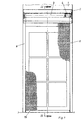
- a roller shutter box is in front of a lintel 1 2 attached with a roller 3 arranged therein.
- the roller 3 has a motor drive 4.
- a link belt 5 made of round wire mesh windable, its individual limbs alternating from one 6 over adjacent horizontal bars Wire 7 exist.
- the rods 6 extend up to lateral grooved rails 8, wherein the in Figs. 3 and 4th Shutter shown grooved rails 8, each from a U-shaped attached to the outside of the door panel 9 Profile 10 with a U-shaped lining 11 made of plastic consist.
- the horizontal rods 6 extend through in the Grooved rails 8 running rollers 12 and are angled behind it.
- the angled ends 13 extend up to behind the rollers 12 of the following rod 6. This it is ensured that a cut rod 6 not pulled out of the groove rail 8 can be.
- an end strip 14 arranged with the last rod 6 of the link belt 5 comprehensive eye bolts 15 and lock nuts 16 is held on the link belt 5.
- the grooved rails 8 are doweled into the door panels 9 Screws 17 attached.
- One adjoining the grooved rail 8 Flange 18 is used for better support.
- FIGS. 5 and 6 Another embodiment is shown in FIGS. 5 and 6 shown.
- the rods 6 to 6 extend in the lateral grooved rails 8, each from an outside on the door panels 9 attached U-shaped profile 10 exist.
- the U-shaped profile 10 is made of two opposite Legs 19, 20 built up on their Have ends inward bends 21, 22.
- the bends 21, 22 are arranged so that they are on the opposite the angled ends of the rod 6 Side of the roller 12.
- the one between the bends 21, 22 formed gap is slightly smaller than the diameter of the roller 12 so that the roller shutter at a break-in attempt, not from the side grooved rails 8, e.g. B. can be pulled or levered.
Landscapes
- Engineering & Computer Science (AREA)
- Structural Engineering (AREA)
- Architecture (AREA)
- Civil Engineering (AREA)
- Operating, Guiding And Securing Of Roll- Type Closing Members (AREA)
- Rolls And Other Rotary Bodies (AREA)
- Wing Frames And Configurations (AREA)
Abstract
Description
- Fig. 1
- die Ansicht einer mit einem Rolladen gesicherten Tür, teilweise geschnitten,
- Fig. 2
- einen Schnitt in Richtung II-II durch den Gegenstand nach Fig. 1,
- Fig. 3
- ein Detail des Gegenstandes nach Fig. 1 in vergrößerter Darstellung,
- Fig. 4
- einen Schnitt in Richtung IV-IV durch den Gegenstand nach Fig. 3,
- Fig. 5
- eine andere Ausführungsform des Gegenstandes nach Fig. 1 in vergrößerter Darstellung und
- Fig. 6
- einen Schnitt in Richtung VI-VI durch den Gegenstand nach Fig. 5.
Claims (8)
- Rolladen für Fenster oder Türen mit einer antreibbaren Walze (3) für ein darauf aufwickelbares Sicherungsgitter, das in seitlichen Nutschienen (8) geführt ist, dadurch gekennzeichnet, dass das Sicherungsgitter aus einem Runddrahtgeflechtgliederband (5) besteht, dessen einzelne Glieder aus einem abwechselnd über benachbarte horizontale Stangen (6) gelegten Draht (7) bestehen, wobei die Stangen (6) sich bis in die seitlichen Nutschienen (8) erstrecken.
- Rolladen nach Anspruch 1, dadurch gekennzeichnet, dass die Stangen (6) sich durch in den Nutschienen (8) laufende Rollen (12) oder Gleitsteine erstrecken und dahinter abgewinkelt sind, wobei die abgewinkelten Enden (13) sich bis hinter die Rolle (12) oder den Gleitstein der nachfolgenden Stange (6) erstrecken.
- Rollade nach Anspruch 1 oder 2, dadurch gekennzeichnet, dass die Nutschienen (8) aus einem U-Profil (10) mit einem U-förmigen Futter (11) aus Kunststoff bestehen.
- Rollade nach Anspruch 1 oder 2, dadurch gekennzeichnet, dass die Nutschienen (8) aus einem U-Profil (10) mit an beiden Schenkeln (19, 20) angeformten und gegeneinander gerichteten Abwinklungen (21, 22) bestehen.
- Rollade nach Anspruch 4 in Kombination mit Anspruch 2, dadurch gekennzeichnet, dass die Abwinklungen (21, 22) jeweils auf der den abgewinkelten Enden der Stangen (6) gegenüberliegenden Seite der Rollen (12) oder Gleitsteine an den Schenkeln (19, 20) angeformt sind und dass der zwischen den gegenüberliegenden Abwinklungen (21, 22) verbleibende Spalt zumindest etwas kleiner als der Durchmesser einer Rolle (12) oder die Dicke eines Gleitsteines ist.
- Rollade nach Anspruch 4 oder 5, dadurch gekennzeichnet, dass im Bereich der Rollen (12) oder der Gleitsteine innenseitig an den Schenkeln (19, 20) Führungsstege (23, 24) vorgesehen sind.
- Rollade nach einem der Ansprüche 1 bis 6, dadurch gekennzeichnet, dass am unteren Ende des Runddrahtgeflechtgliederbandes (5) eine in den Nutschienen (8) geführte Abschlussleiste (14) angeordnet ist.
- Rollade nach einem der Ansprüche 1 bis 7, dadurch gekennzeichnet, dass die Abschlussleiste (14) mit die letzte Stange (6) des Runddrahtgeflechtgliederbandes (5) überfassenden Augenschrauben (15) befestigt ist.
Applications Claiming Priority (2)
| Application Number | Priority Date | Filing Date | Title |
|---|---|---|---|
| DE29903358U | 1999-02-25 | ||
| DE29903358U DE29903358U1 (de) | 1999-02-25 | 1999-02-25 | Rolladen für Fenster oder Türen |
Publications (3)
| Publication Number | Publication Date |
|---|---|
| EP1031700A2 true EP1031700A2 (de) | 2000-08-30 |
| EP1031700A3 EP1031700A3 (de) | 2001-05-02 |
| EP1031700B1 EP1031700B1 (de) | 2005-04-13 |
Family
ID=8069914
Family Applications (1)
| Application Number | Title | Priority Date | Filing Date |
|---|---|---|---|
| EP00103658A Expired - Lifetime EP1031700B1 (de) | 1999-02-25 | 2000-02-22 | Rolladen für Fenster oder Türen |
Country Status (3)
| Country | Link |
|---|---|
| EP (1) | EP1031700B1 (de) |
| AT (1) | ATE293201T1 (de) |
| DE (2) | DE29903358U1 (de) |
Families Citing this family (2)
| Publication number | Priority date | Publication date | Assignee | Title |
|---|---|---|---|---|
| DE19962546A1 (de) * | 1999-12-23 | 2001-07-05 | Biffar Kg Oskar D | Absperrvorrichtung für Durchgangsöffnungen in Gebäuden |
| IT1403881B1 (it) * | 2010-02-15 | 2013-11-08 | Resstende S R L | Struttura di tenda a rullo, particolarmente per schermare superfici vetrate. |
Family Cites Families (2)
| Publication number | Priority date | Publication date | Assignee | Title |
|---|---|---|---|---|
| CH140941A (de) * | 1929-10-01 | 1930-07-15 | Wismer Julius | Rollvorhang für Toreingänge, Türen, Fenster etc. |
| US2048840A (en) * | 1935-04-26 | 1936-07-28 | Cornell Iron Works Inc | Flexible grille |
-
1999
- 1999-02-25 DE DE29903358U patent/DE29903358U1/de not_active Expired - Lifetime
-
2000
- 2000-02-22 AT AT00103658T patent/ATE293201T1/de not_active IP Right Cessation
- 2000-02-22 DE DE50010023T patent/DE50010023D1/de not_active Expired - Lifetime
- 2000-02-22 EP EP00103658A patent/EP1031700B1/de not_active Expired - Lifetime
Also Published As
| Publication number | Publication date |
|---|---|
| DE50010023D1 (de) | 2005-05-19 |
| DE29903358U1 (de) | 1999-05-12 |
| ATE293201T1 (de) | 2005-04-15 |
| EP1031700B1 (de) | 2005-04-13 |
| EP1031700A3 (de) | 2001-05-02 |
Similar Documents
| Publication | Publication Date | Title |
|---|---|---|
| DE19758648C2 (de) | Crashschutzvorrichtung für Schnellaufrolltore sowie Schnellaufrolltor | |
| EP0558973B1 (de) | Schiebetor | |
| EP1003952B1 (de) | Tür- oder torverschluss | |
| DE2703512C2 (de) | Rolltor für Hallen o.dgl. | |
| DE2947501A1 (de) | Ein- und ausfahrbare abdeckvorrichtung, insbesondere rolladen fuer fenster, tueren, tore o.dgl. | |
| DE3320947C2 (de) | Bogenförmig verschiebbares Schiebetor | |
| DE3835055C2 (de) | ||
| DE4031388C2 (de) | Seitensektionaltor oder Rundlauftor, Deckensektionaltor | |
| EP1031700B1 (de) | Rolladen für Fenster oder Türen | |
| EP0716213A1 (de) | Hochschiebesicherung für Rolläden und Rolltore | |
| DE884097C (de) | Rollverschluss fuer Tueren, Fenster u. dgl. | |
| DE3515404C2 (de) | ||
| EP0003728B1 (de) | Feuerschutzrolltor | |
| DE3328138C2 (de) | Sicherheitsverriegelung | |
| AT508177B1 (de) | Rollladen mit führungsschienen und anschlägen | |
| DE102009051344A1 (de) | Folientor | |
| DE202007013061U1 (de) | Brandschutzrolladen | |
| DE202007019187U1 (de) | Sektionaltor | |
| DE9419412U1 (de) | Hochschiebesicherung für Rolläden und Rolltore | |
| DE4015529A1 (de) | Rolladen | |
| EP2444583B1 (de) | Torsäule für ein Rolltor | |
| DE102020103603B4 (de) | Hochwasserbeständiges Sektionaltor | |
| EP2089601B1 (de) | Verschlussanordnung | |
| DE29508931U1 (de) | Einbauelement für den Abschluß einer Gebäudeöffnung | |
| CH684018A5 (de) | Schiebetor. |
Legal Events
| Date | Code | Title | Description |
|---|---|---|---|
| PUAI | Public reference made under article 153(3) epc to a published international application that has entered the european phase |
Free format text: ORIGINAL CODE: 0009012 |
|
| AK | Designated contracting states |
Kind code of ref document: A2 Designated state(s): AT BE CH CY DE DK ES FI FR GB GR IE IT LI LU MC NL PT SE |
|
| AX | Request for extension of the european patent |
Free format text: AL;LT;LV;MK;RO;SI |
|
| PUAL | Search report despatched |
Free format text: ORIGINAL CODE: 0009013 |
|
| AK | Designated contracting states |
Kind code of ref document: A3 Designated state(s): AT BE CH CY DE DK ES FI FR GB GR IE IT LI LU MC NL PT SE |
|
| AX | Request for extension of the european patent |
Free format text: AL;LT;LV;MK;RO;SI |
|
| 17P | Request for examination filed |
Effective date: 20010816 |
|
| AKX | Designation fees paid |
Free format text: AT BE CH CY DE DK ES FI FR GB GR IE IT LI LU MC NL PT SE |
|
| GRAP | Despatch of communication of intention to grant a patent |
Free format text: ORIGINAL CODE: EPIDOSNIGR1 |
|
| GRAS | Grant fee paid |
Free format text: ORIGINAL CODE: EPIDOSNIGR3 |
|
| GRAA | (expected) grant |
Free format text: ORIGINAL CODE: 0009210 |
|
| AK | Designated contracting states |
Kind code of ref document: B1 Designated state(s): AT BE CH CY DE DK ES FI FR GB GR IE IT LI LU MC NL PT SE |
|
| PG25 | Lapsed in a contracting state [announced via postgrant information from national office to epo] |
Ref country code: IT Free format text: LAPSE BECAUSE OF FAILURE TO SUBMIT A TRANSLATION OF THE DESCRIPTION OR TO PAY THE FEE WITHIN THE PRESCRIBED TIME-LIMIT;WARNING: LAPSES OF ITALIAN PATENTS WITH EFFECTIVE DATE BEFORE 2007 MAY HAVE OCCURRED AT ANY TIME BEFORE 2007. THE CORRECT EFFECTIVE DATE MAY BE DIFFERENT FROM THE ONE RECORDED. Effective date: 20050413 Ref country code: GB Free format text: LAPSE BECAUSE OF FAILURE TO SUBMIT A TRANSLATION OF THE DESCRIPTION OR TO PAY THE FEE WITHIN THE PRESCRIBED TIME-LIMIT Effective date: 20050413 Ref country code: NL Free format text: LAPSE BECAUSE OF FAILURE TO SUBMIT A TRANSLATION OF THE DESCRIPTION OR TO PAY THE FEE WITHIN THE PRESCRIBED TIME-LIMIT Effective date: 20050413 Ref country code: FI Free format text: LAPSE BECAUSE OF FAILURE TO SUBMIT A TRANSLATION OF THE DESCRIPTION OR TO PAY THE FEE WITHIN THE PRESCRIBED TIME-LIMIT Effective date: 20050413 Ref country code: IE Free format text: LAPSE BECAUSE OF FAILURE TO SUBMIT A TRANSLATION OF THE DESCRIPTION OR TO PAY THE FEE WITHIN THE PRESCRIBED TIME-LIMIT Effective date: 20050413 |
|
| REG | Reference to a national code |
Ref country code: GB Ref legal event code: FG4D Free format text: NOT ENGLISH |
|
| REG | Reference to a national code |
Ref country code: CH Ref legal event code: EP |
|
| REG | Reference to a national code |
Ref country code: IE Ref legal event code: FG4D Free format text: LANGUAGE OF EP DOCUMENT: GERMAN |
|
| REF | Corresponds to: |
Ref document number: 50010023 Country of ref document: DE Date of ref document: 20050519 Kind code of ref document: P |
|
| PG25 | Lapsed in a contracting state [announced via postgrant information from national office to epo] |
Ref country code: SE Free format text: LAPSE BECAUSE OF FAILURE TO SUBMIT A TRANSLATION OF THE DESCRIPTION OR TO PAY THE FEE WITHIN THE PRESCRIBED TIME-LIMIT Effective date: 20050713 Ref country code: DK Free format text: LAPSE BECAUSE OF FAILURE TO SUBMIT A TRANSLATION OF THE DESCRIPTION OR TO PAY THE FEE WITHIN THE PRESCRIBED TIME-LIMIT Effective date: 20050713 Ref country code: GR Free format text: LAPSE BECAUSE OF FAILURE TO SUBMIT A TRANSLATION OF THE DESCRIPTION OR TO PAY THE FEE WITHIN THE PRESCRIBED TIME-LIMIT Effective date: 20050713 |
|
| PG25 | Lapsed in a contracting state [announced via postgrant information from national office to epo] |
Ref country code: ES Free format text: LAPSE BECAUSE OF FAILURE TO SUBMIT A TRANSLATION OF THE DESCRIPTION OR TO PAY THE FEE WITHIN THE PRESCRIBED TIME-LIMIT Effective date: 20050724 |
|
| PG25 | Lapsed in a contracting state [announced via postgrant information from national office to epo] |
Ref country code: PT Free format text: LAPSE BECAUSE OF FAILURE TO SUBMIT A TRANSLATION OF THE DESCRIPTION OR TO PAY THE FEE WITHIN THE PRESCRIBED TIME-LIMIT Effective date: 20050913 |
|
| NLV1 | Nl: lapsed or annulled due to failure to fulfill the requirements of art. 29p and 29m of the patents act | ||
| GBV | Gb: ep patent (uk) treated as always having been void in accordance with gb section 77(7)/1977 [no translation filed] |
Effective date: 20050413 |
|
| REG | Reference to a national code |
Ref country code: IE Ref legal event code: FD4D |
|
| PLBE | No opposition filed within time limit |
Free format text: ORIGINAL CODE: 0009261 |
|
| STAA | Information on the status of an ep patent application or granted ep patent |
Free format text: STATUS: NO OPPOSITION FILED WITHIN TIME LIMIT |
|
| PG25 | Lapsed in a contracting state [announced via postgrant information from national office to epo] |
Ref country code: BE Free format text: LAPSE BECAUSE OF NON-PAYMENT OF DUE FEES Effective date: 20060228 Ref country code: LU Free format text: LAPSE BECAUSE OF NON-PAYMENT OF DUE FEES Effective date: 20060228 Ref country code: MC Free format text: LAPSE BECAUSE OF NON-PAYMENT OF DUE FEES Effective date: 20060228 |
|
| 26N | No opposition filed |
Effective date: 20060116 |
|
| EN | Fr: translation not filed | ||
| BERE | Be: lapsed |
Owner name: VORRICHTUNGS- UND MASCHINENBAU, ALBERT SCHOOF INH Effective date: 20060228 |
|
| PG25 | Lapsed in a contracting state [announced via postgrant information from national office to epo] |
Ref country code: FR Free format text: LAPSE BECAUSE OF FAILURE TO SUBMIT A TRANSLATION OF THE DESCRIPTION OR TO PAY THE FEE WITHIN THE PRESCRIBED TIME-LIMIT Effective date: 20050413 Ref country code: CY Free format text: LAPSE BECAUSE OF FAILURE TO SUBMIT A TRANSLATION OF THE DESCRIPTION OR TO PAY THE FEE WITHIN THE PRESCRIBED TIME-LIMIT Effective date: 20050413 |
|
| PGFP | Annual fee paid to national office [announced via postgrant information from national office to epo] |
Ref country code: AT Payment date: 20090219 Year of fee payment: 10 |
|
| PGFP | Annual fee paid to national office [announced via postgrant information from national office to epo] |
Ref country code: CH Payment date: 20090223 Year of fee payment: 10 |
|
| REG | Reference to a national code |
Ref country code: CH Ref legal event code: PL |
|
| PG25 | Lapsed in a contracting state [announced via postgrant information from national office to epo] |
Ref country code: CH Free format text: LAPSE BECAUSE OF NON-PAYMENT OF DUE FEES Effective date: 20100228 Ref country code: LI Free format text: LAPSE BECAUSE OF NON-PAYMENT OF DUE FEES Effective date: 20100228 |
|
| PG25 | Lapsed in a contracting state [announced via postgrant information from national office to epo] |
Ref country code: AT Free format text: LAPSE BECAUSE OF NON-PAYMENT OF DUE FEES Effective date: 20100222 |
|
| PGFP | Annual fee paid to national office [announced via postgrant information from national office to epo] |
Ref country code: DE Payment date: 20110318 Year of fee payment: 12 |
|
| REG | Reference to a national code |
Ref country code: DE Ref legal event code: R119 Ref document number: 50010023 Country of ref document: DE Effective date: 20120901 |
|
| PG25 | Lapsed in a contracting state [announced via postgrant information from national office to epo] |
Ref country code: DE Free format text: LAPSE BECAUSE OF NON-PAYMENT OF DUE FEES Effective date: 20120901 |