EP1031714A2 - Reservoir de distribution pour un moteur à combustion interne - Google Patents
Reservoir de distribution pour un moteur à combustion interne Download PDFInfo
- Publication number
- EP1031714A2 EP1031714A2 EP99309076A EP99309076A EP1031714A2 EP 1031714 A2 EP1031714 A2 EP 1031714A2 EP 99309076 A EP99309076 A EP 99309076A EP 99309076 A EP99309076 A EP 99309076A EP 1031714 A2 EP1031714 A2 EP 1031714A2
- Authority
- EP
- European Patent Office
- Prior art keywords
- manifold
- intake
- secondary gas
- reservoir
- throttle body
- Prior art date
- Legal status (The legal status is an assumption and is not a legal conclusion. Google has not performed a legal analysis and makes no representation as to the accuracy of the status listed.)
- Granted
Links
Images



Classifications
-
- F—MECHANICAL ENGINEERING; LIGHTING; HEATING; WEAPONS; BLASTING
- F02—COMBUSTION ENGINES; HOT-GAS OR COMBUSTION-PRODUCT ENGINE PLANTS
- F02M—SUPPLYING COMBUSTION ENGINES IN GENERAL WITH COMBUSTIBLE MIXTURES OR CONSTITUENTS THEREOF
- F02M35/00—Combustion-air cleaners, air intakes, intake silencers, or induction systems specially adapted for, or arranged on, internal-combustion engines
- F02M35/10—Air intakes; Induction systems
- F02M35/10209—Fluid connections to the air intake system; their arrangement of pipes, valves or the like
- F02M35/10222—Exhaust gas recirculation [EGR]; Positive crankcase ventilation [PCV]; Additional air admission, lubricant or fuel vapour admission
-
- F—MECHANICAL ENGINEERING; LIGHTING; HEATING; WEAPONS; BLASTING
- F02—COMBUSTION ENGINES; HOT-GAS OR COMBUSTION-PRODUCT ENGINE PLANTS
- F02B—INTERNAL-COMBUSTION PISTON ENGINES; COMBUSTION ENGINES IN GENERAL
- F02B47/00—Methods of operating engines involving adding non-fuel substances or anti-knock agents to combustion air, fuel, or fuel-air mixtures of engines
- F02B47/04—Methods of operating engines involving adding non-fuel substances or anti-knock agents to combustion air, fuel, or fuel-air mixtures of engines the substances being other than water or steam only
- F02B47/08—Methods of operating engines involving adding non-fuel substances or anti-knock agents to combustion air, fuel, or fuel-air mixtures of engines the substances being other than water or steam only the substances including exhaust gas
-
- F—MECHANICAL ENGINEERING; LIGHTING; HEATING; WEAPONS; BLASTING
- F02—COMBUSTION ENGINES; HOT-GAS OR COMBUSTION-PRODUCT ENGINE PLANTS
- F02B—INTERNAL-COMBUSTION PISTON ENGINES; COMBUSTION ENGINES IN GENERAL
- F02B75/00—Other engines
- F02B75/16—Engines characterised by number of cylinders, e.g. single-cylinder engines
- F02B75/18—Multi-cylinder engines
- F02B75/22—Multi-cylinder engines with cylinders in V, fan, or star arrangement
-
- F—MECHANICAL ENGINEERING; LIGHTING; HEATING; WEAPONS; BLASTING
- F02—COMBUSTION ENGINES; HOT-GAS OR COMBUSTION-PRODUCT ENGINE PLANTS
- F02D—CONTROLLING COMBUSTION ENGINES
- F02D21/00—Controlling engines characterised by their being supplied with non-airborne oxygen or other non-fuel gas
- F02D21/06—Controlling engines characterised by their being supplied with non-airborne oxygen or other non-fuel gas peculiar to engines having other non-fuel gas added to combustion air
- F02D21/08—Controlling engines characterised by their being supplied with non-airborne oxygen or other non-fuel gas peculiar to engines having other non-fuel gas added to combustion air the other gas being the exhaust gas of engine
-
- F—MECHANICAL ENGINEERING; LIGHTING; HEATING; WEAPONS; BLASTING
- F02—COMBUSTION ENGINES; HOT-GAS OR COMBUSTION-PRODUCT ENGINE PLANTS
- F02M—SUPPLYING COMBUSTION ENGINES IN GENERAL WITH COMBUSTIBLE MIXTURES OR CONSTITUENTS THEREOF
- F02M35/00—Combustion-air cleaners, air intakes, intake silencers, or induction systems specially adapted for, or arranged on, internal-combustion engines
- F02M35/10—Air intakes; Induction systems
- F02M35/104—Intake manifolds
- F02M35/1045—Intake manifolds characterised by the charge distribution between the cylinders/combustion chambers or its homogenisation
-
- F—MECHANICAL ENGINEERING; LIGHTING; HEATING; WEAPONS; BLASTING
- F02—COMBUSTION ENGINES; HOT-GAS OR COMBUSTION-PRODUCT ENGINE PLANTS
- F02M—SUPPLYING COMBUSTION ENGINES IN GENERAL WITH COMBUSTIBLE MIXTURES OR CONSTITUENTS THEREOF
- F02M35/00—Combustion-air cleaners, air intakes, intake silencers, or induction systems specially adapted for, or arranged on, internal-combustion engines
- F02M35/10—Air intakes; Induction systems
- F02M35/104—Intake manifolds
- F02M35/116—Intake manifolds for engines with cylinders in V-arrangement or arranged oppositely relative to the main shaft
-
- F—MECHANICAL ENGINEERING; LIGHTING; HEATING; WEAPONS; BLASTING
- F02—COMBUSTION ENGINES; HOT-GAS OR COMBUSTION-PRODUCT ENGINE PLANTS
- F02B—INTERNAL-COMBUSTION PISTON ENGINES; COMBUSTION ENGINES IN GENERAL
- F02B75/00—Other engines
- F02B75/16—Engines characterised by number of cylinders, e.g. single-cylinder engines
- F02B75/18—Multi-cylinder engines
- F02B2075/1804—Number of cylinders
- F02B2075/1824—Number of cylinders six
-
- F—MECHANICAL ENGINEERING; LIGHTING; HEATING; WEAPONS; BLASTING
- F02—COMBUSTION ENGINES; HOT-GAS OR COMBUSTION-PRODUCT ENGINE PLANTS
- F02M—SUPPLYING COMBUSTION ENGINES IN GENERAL WITH COMBUSTIBLE MIXTURES OR CONSTITUENTS THEREOF
- F02M35/00—Combustion-air cleaners, air intakes, intake silencers, or induction systems specially adapted for, or arranged on, internal-combustion engines
- F02M35/10—Air intakes; Induction systems
- F02M35/10006—Air intakes; Induction systems characterised by the position of elements of the air intake system in direction of the air intake flow, i.e. between ambient air inlet and supply to the combustion chamber
- F02M35/10026—Plenum chambers
- F02M35/10045—Multiple plenum chambers; Plenum chambers having inner separation walls
-
- Y—GENERAL TAGGING OF NEW TECHNOLOGICAL DEVELOPMENTS; GENERAL TAGGING OF CROSS-SECTIONAL TECHNOLOGIES SPANNING OVER SEVERAL SECTIONS OF THE IPC; TECHNICAL SUBJECTS COVERED BY FORMER USPC CROSS-REFERENCE ART COLLECTIONS [XRACs] AND DIGESTS
- Y02—TECHNOLOGIES OR APPLICATIONS FOR MITIGATION OR ADAPTATION AGAINST CLIMATE CHANGE
- Y02T—CLIMATE CHANGE MITIGATION TECHNOLOGIES RELATED TO TRANSPORTATION
- Y02T10/00—Road transport of goods or passengers
- Y02T10/10—Internal combustion engine [ICE] based vehicles
- Y02T10/12—Improving ICE efficiencies
Definitions
- the present invention relates to a system and method for secondary gas introduction, including but not limited to Exhaust Gas Recirculation (EGR), Positive Crankcase Ventilation (PCV) and Evaporative Emissions (EVAP), into the air induction system for a multi-cylinder internal combustion engine, and more particularly to a reservoir for introducing secondary gas into the induction system.
- EGR Exhaust Gas Recirculation
- PCV Positive Crankcase Ventilation
- EVAP Evaporative Emissions
- U.S. Patent 5,590,488 describes an intake manifold having an Exhaust Gas Recirculation (EGR) passage formed therein extending generally parallel to a cooling passage formed in the manifold.
- EGR Exhaust Gas Recirculation
- the EGR flow in the '488 patent is considered ported because EGR flows through secondary EGR passages extending from the EGR supply passage to individual runners in the intake manifold.
- the EGR ports are provided in close proximity to the cylinder head.
- the EGR ports are provided within the individual intake runners, which results in communication between the ports.
- Such communication short circuits a tuned induction system, resulting in a degradation of engine performance and can provide for unequal distribution of EGR.
- This unequal distribution can also affect engine performance and emissions because the EGR is not properly controlled between cylinders. This makes it difficult to control the EGR to ensure smooth running of the engine.
- U.S. Patents 5,535,717 and 5,492.093 provide a system for introducing EGR into the an air induction system. These patents provide introduction of EGR within a balance tube, or into one of the runners, or a primary runner. This system does not promote equal distribution or mixing, as air is typically stagnant in the primary runner unless balance tube valve and the intake valves for the cylinders are open, and therefore distribution of the EGR is uneven between the cylinder banks. As described above, this unequal distribution may produce undesirable operation of the vehicle.
- a valve for such a balance tube is open normally in mid-range operation, such as between approximately 3000 and 4500 RPM. Thus, outside this range (at low speed or high speed operation), the balance valve is closed and the EGR gas is not properly mixed, and therefore an inefficient, unequal cylinder bank distribution exists.
- an intake manifold for a multi-cylinder reciprocating internal combustion engine having a cylinder block with a cylinder head mounted thereto, said manifold comprising a plurality of intake runners for conducting air to a plurality of intake ports formed in the cylinder heads; an intake plenum communicating with said plurality of intake runners; and a secondary gas supply reservoir provided in said manifold for distribution of a secondary gas to said plenum.
- a method of supplying secondary gas to a plenum in a manifold of a multicylinder engine the manifold supplying fluids to a plurality of combustion chambers in said engine, the manifold further having a throttle body attached thereto, which method comprises providing a secondary gas reservoir in said manifold downstream from said throttle body; supplying a secondary gas to said reservoir; and distributing the secondary gas to a plenum as air is drawn through said throttle body into said manifold, said plenum being in further fluid communication with a plurality of intake runners in said manifold.
- an intake manifold for a multi-cylinder reciprocating internal combustion engine having a cylinder block with a cylinder head mounted thereto, said manifold comprising a plurality of intake runners for conducting air and a secondary gas to a plurality of intake ports formed in the cylinder head; a pair of intake plenums communicating with the plurality of intake runners; and a secondary gas supply reservoir provided in said manifold for communication of secondary gas to said plenums.
- Advantages of the present design include proper distribution and mixing of additional gases introduced into the intake system, including idle air, PCV and EVAP and other fluids at separate or coincidental supply reservoirs.
- an intake manifold 10 having a provision for mounting a throttle body 12 thereto.
- the throttle regulates the flow of a primary air flow gas, which is defined as the induction air brought into the manifold through the throttle body from ambient.
- the throttle body 12 comprises a valve which is adjusted using a throttle adjustment means 13 as known to one skilled in the art, such as a cable or electronic adjuster.
- the manifold includes a plurality of primary runners 60, 61, 62, 63, 64, 65, 66 and 67.
- the primary runners 60-67 distribute gases, including the primary air flow gas and secondary gases, to the intake ports.
- a representative intake port is illustrated in Figure 7 at 23, and is provided in the heads 30, 31 of an internal combustion engine 28 to provide intake air to a combustion chamber 27.
- the present invention is applicable to a port fuel injection engine as well as a direct injection engine, and therefore the detail of the injector and spark plug positioning are not illustrated in Figure 7.
- the secondary gases include any other gas introduced into the induction system downstream of the throttle body. These gases typically require mixing within the induction system to provide equal cylinder-to-cylinder distribution and thereby promote smooth operation of the engine and to improve the emissions therefrom.
- the present invention is directed at providing a manifold and a method enabling such mixing and nearly equal distribution.
- the secondary gases include, but are not limited to, recirculated exhaust gas (EGR), EVAP, idle air and PCV.
- EGR is introduced into the manifold 10 through a tube 14.
- a known valve 15 for EGR regulates the flow of the exhaust gas introduced into the manifold 10.
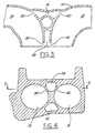
- the EGR is fed into a reservoir 16 in the manifold 10 as is shown in Figure 2.
- exhaust gas is drawn from the reservoir 16 through a pair of orifices 20, 22 provided in the manifold 10 leading between the runners 18, 19 and the reservoir 16. In this manner, the exhaust gas is stored in the reservoir 16 and provided early in the intake system soon after the throttle 12 upon demand.
- the EGR is thus drawn from the reservoir 16 and distributed to the secondary intake runners 18, 19 for introduction to the plenums 24, 25, then to primary runners 60-67 and ultimately into the cylinders (not shown) through a plurality of intake ports (not shown). This early introduction into the manifold 10 near the throttle 12 enables mixing within the manifold 10 and nearly equal distribution to all of the cylinders.
- the throttling of the gas at the throttle causes a venturi effect at the reservoir and sucks the secondary gas from the reservoir for mixing within the intake manifold prior to the air/fuel/secondary gas mixture being pulled into a primary runner.
- the throttle is closed and idle air is introduced into the intake manifold, the idle air draws the secondary gases from the reservoir.
- a tuned induction system is shortcircuited using a balance tube 40 and balance tube communication valve 42 to tune the intake system and thereby improve the performance of the induction system and engine performance.
- the tuning principle and examples thereof are described in US patents 5,408,962 and 5,638,785, assigned to the assignee of the present invention and which are incorporated herein by reference in their entirety.
- PCV Positive Crankcase Ventilation
- EVAP Evaporative Emissions
- idle air alternate fuels such as CNG, LPG
- performance enhancing fuels and/or other gases may likewise be introduced into the manifold 10 within the reservoir 16 or a second reservoir 28 for distribution as described above.
- PCV Positive Crankcase Ventilation
- EVAP Evaporative Emissions
- idle air alternate fuels such as CNG, LPG
- CNG Charge gas
- LPG performance enhancing fuels and/or other gases
- PCV is introduced to the reservoir 16 through a second port 26 and thereby equally distribute this supply of PCV to the secondary intake runners 18, 19 in a manner similar to that described above for the EGR.
- a preferred embodiment includes a second reservoir 28 provided for the idle air and EVAP.
- an idle air valve 32 controls the flow of idle air to the reservoir 28 through a conduit 36.
- EVAP is introduced to the conduit 36 and to the reservoir 28 at a connection 34 provided therefor.
- Idle air is introduced through the throttle 12 to a port 38 in the manifold 10. The idle air is then routed to the valve 32 and introduced to the reservoir 28 as described above.
- the first reservoir 16 for the PCV and EGR is provided in close proximity to the second reservoir 28 and therefore the distribution of these gases is provided in a manner as described above.
- EGR, PCV, EVAP or idle air may also be supplied in either one of the reservoirs 16 and 28 and/or in other separate reservoirs (not shown) for mixing and nearly equal distribution to the secondary intake runners 18, 19, as demanded by the engine.
- the second reservoir 28 distributes EVAP to the secondary intake runners 18, 19 through orifices 30, 32 in a manner similar to the gas distribution from first reservoir 16, as described above.
- the reservoirs 16, 28 are positioned adjacent and downstream of the throttle body 12.
- the reservoirs 16, 28 store the gases until demand from the engine draws the gases from the reservoirs into the secondary intake runners 18, 19, as demanded by the engine, and is therefore distributed to the cylinders in an equal manner.
- the present invention can likewise be applied to: a single bore throttle body with single plenum, single bore throttle body with multiple plenums, dual bore throttle body with single plenum, dual bore throttle body with multiple plenums (illustrated in the Figures) providing the advantage of minimizing induction tuning loses by introducing the secondary emissions gasses as far away from the cylinder ports as packaging will permit.
- a V-type engine is illustrated in the figures, this disclosure is directed at other engine configurations, not described here in specific detail.
Landscapes
- Engineering & Computer Science (AREA)
- Chemical & Material Sciences (AREA)
- Combustion & Propulsion (AREA)
- Mechanical Engineering (AREA)
- General Engineering & Computer Science (AREA)
- Exhaust-Gas Circulating Devices (AREA)
- Supplying Secondary Fuel Or The Like To Fuel, Air Or Fuel-Air Mixtures (AREA)
Applications Claiming Priority (2)
| Application Number | Priority Date | Filing Date | Title |
|---|---|---|---|
| US257654 | 1999-02-25 | ||
| US09/257,654 US6155223A (en) | 1999-02-25 | 1999-02-25 | Distribution reservoir for an internal combustion engine |
Publications (3)
| Publication Number | Publication Date |
|---|---|
| EP1031714A2 true EP1031714A2 (fr) | 2000-08-30 |
| EP1031714A3 EP1031714A3 (fr) | 2001-09-12 |
| EP1031714B1 EP1031714B1 (fr) | 2006-03-15 |
Family
ID=22977188
Family Applications (1)
| Application Number | Title | Priority Date | Filing Date |
|---|---|---|---|
| EP99309076A Expired - Lifetime EP1031714B1 (fr) | 1999-02-25 | 1999-11-15 | Reservoir de distribution pour un moteur à combustion interne |
Country Status (3)
| Country | Link |
|---|---|
| US (1) | US6155223A (fr) |
| EP (1) | EP1031714B1 (fr) |
| DE (1) | DE69930355T2 (fr) |
Families Citing this family (9)
| Publication number | Priority date | Publication date | Assignee | Title |
|---|---|---|---|---|
| US6691686B2 (en) | 2001-12-28 | 2004-02-17 | Visteon Global Technologies, Inc. | Intake manifold with improved exhaust gas recirculation |
| US7093589B2 (en) * | 2004-01-08 | 2006-08-22 | Visteon Global Technologies, Inc. | Apparatus for increasing induction air flow rate to a turbocharger |
| US8511289B2 (en) * | 2009-05-18 | 2013-08-20 | Aisan Kogyo Kabushiki Kaisha | Intake manifolds |
| US9322364B2 (en) * | 2013-07-22 | 2016-04-26 | GM Global Technology Operations LLC | Engine inlet for EGR-air flow distribution |
| USD766986S1 (en) | 2014-07-29 | 2016-09-20 | Kohler, Co. | Engine |
| US9541044B2 (en) | 2015-01-27 | 2017-01-10 | Ford Global Technologies, Llc | Intake manifold secondary gas distribution via structural posts |
| JP6580518B2 (ja) * | 2016-05-12 | 2019-09-25 | 株式会社豊田自動織機 | 内燃機関の吸気装置 |
| JP6563362B2 (ja) * | 2016-05-12 | 2019-08-21 | 株式会社豊田自動織機 | 内燃機関の吸気装置 |
| JP2021011833A (ja) * | 2019-07-04 | 2021-02-04 | アイシン精機株式会社 | 吸入装置 |
Family Cites Families (17)
| Publication number | Priority date | Publication date | Assignee | Title |
|---|---|---|---|---|
| JPS6270653A (ja) * | 1985-09-24 | 1987-04-01 | Yamaha Motor Co Ltd | V形エンジンの排気浄化装置 |
| JPS6285163A (ja) * | 1985-10-11 | 1987-04-18 | Yamaha Motor Co Ltd | V形エンジンの排気浄化装置 |
| GB2191818A (en) * | 1986-06-20 | 1987-12-23 | Ford Motor Co | Tuned inlet manifold |
| JP2767441B2 (ja) * | 1988-11-25 | 1998-06-18 | ヤマハ発動機株式会社 | V型多気筒エンジンの吸気装置 |
| JP2778727B2 (ja) * | 1989-03-03 | 1998-07-23 | ヤマハ発動機株式会社 | エンジンの吸気装置 |
| GB2256674A (en) * | 1991-06-10 | 1992-12-16 | Ford Motor Co | Acoustic pipe coupling. |
| GB2256675A (en) * | 1991-06-11 | 1992-12-16 | Ford Motor Co | Tuned i.c.engine intake system. |
| US5267543A (en) * | 1992-12-21 | 1993-12-07 | Ford Motor Company | Dual induction system for internal combustion engine |
| US5408962A (en) * | 1994-07-05 | 1995-04-25 | Ford Motor Company | Engine performance improvement |
| US5492093A (en) * | 1994-09-02 | 1996-02-20 | Chrysler Corporation | Fluid distributing in dual intake manifolds |
| US5535717A (en) * | 1994-09-02 | 1996-07-16 | Chrysler Corporation | Fluid distribution method in dual intake manifolds |
| JP3210825B2 (ja) * | 1995-01-14 | 2001-09-25 | ヤマハ発動機株式会社 | V型多気筒エンジンの吸気装置 |
| US5490488A (en) * | 1995-04-05 | 1996-02-13 | Ford Motor Company | Internal combustion engine intake manifold with integral EGR cooler and ported EGR flow passages |
| US5740778A (en) * | 1996-03-22 | 1998-04-21 | Ford Global Technologies, Inc. | Variable geometry intake system for an internal combustion engine |
| JPH09303225A (ja) * | 1996-05-16 | 1997-11-25 | Suzuki Motor Corp | インテークマニホールドの支持構造 |
| US5638785A (en) * | 1996-10-15 | 1997-06-17 | Ford Motor Company | Variable air intake manifold |
| US5762036A (en) * | 1997-01-16 | 1998-06-09 | Ford Global Technologies, Inc. | Split plenum intake manifold with variable runners |
-
1999
- 1999-02-25 US US09/257,654 patent/US6155223A/en not_active Expired - Lifetime
- 1999-11-15 DE DE69930355T patent/DE69930355T2/de not_active Expired - Lifetime
- 1999-11-15 EP EP99309076A patent/EP1031714B1/fr not_active Expired - Lifetime
Also Published As
| Publication number | Publication date |
|---|---|
| EP1031714B1 (fr) | 2006-03-15 |
| EP1031714A3 (fr) | 2001-09-12 |
| DE69930355D1 (de) | 2006-05-11 |
| US6155223A (en) | 2000-12-05 |
| DE69930355T2 (de) | 2006-08-03 |
Similar Documents
| Publication | Publication Date | Title |
|---|---|---|
| US6053154A (en) | Exhaust gas recycling arrangement with individual cylinder throttling | |
| US6039029A (en) | Induction system for fuel injected engine | |
| US9322364B2 (en) | Engine inlet for EGR-air flow distribution | |
| US5657727A (en) | V-type engine induction system | |
| EP0801224A3 (fr) | Dispositif d'admission d'air pour moteur à combustion interne | |
| US5307784A (en) | Induction system for internal combustion engine | |
| US7036493B1 (en) | Intake manifold for an internal combustion engine | |
| US5813375A (en) | Method and system for distributing vapors or gases to each cylinder of a multicylinder engine | |
| EP1031714B1 (fr) | Reservoir de distribution pour un moteur à combustion interne | |
| JPS59231161A (ja) | 内燃機関の補助空気供給装置 | |
| US5146897A (en) | Intake manifold of intake system for multi-cylinder internal combustion engine | |
| US7240669B2 (en) | Method of operating an internal combustion engine with a dual fuel injection system | |
| GB2386158A (en) | Intake system for internal combustion engine | |
| US6655337B2 (en) | V-type 2-cylinder engine | |
| US6918383B2 (en) | Fuel control system | |
| US7296563B2 (en) | Internal combustion engine intake device | |
| US4479470A (en) | Intake passage structure for internal combustion engines | |
| WO1993000505A3 (fr) | Collecteur d'admission pour un moteur a combustion interne a plusieurs cylindres | |
| JP2008075522A (ja) | 排気ガス還流装置を備える多気筒内燃機関 | |
| US20060090722A1 (en) | Intake manifold spacer for an internal combustion engine | |
| US5056474A (en) | Internal combustion engine having multiple carburetors and a starting mixture | |
| US6622687B2 (en) | Intake apparatus of multi-cylinder internal combustion engine | |
| JP2000220540A (ja) | 吸気マニホールド構造 | |
| JP3143687B2 (ja) | 多気筒エンジンの吸気マニホールド | |
| EP0953761B1 (fr) | Moteur à combustion interne avec canal auxiliaire d'admission |
Legal Events
| Date | Code | Title | Description |
|---|---|---|---|
| PUAI | Public reference made under article 153(3) epc to a published international application that has entered the european phase |
Free format text: ORIGINAL CODE: 0009012 |
|
| AK | Designated contracting states |
Kind code of ref document: A2 Designated state(s): AT BE CH CY DE DK ES FI FR GB GR IE IT LI LU MC NL PT SE Kind code of ref document: A2 Designated state(s): DE FR GB |
|
| AX | Request for extension of the european patent |
Free format text: AL;LT;LV;MK;RO;SI |
|
| PUAL | Search report despatched |
Free format text: ORIGINAL CODE: 0009013 |
|
| AK | Designated contracting states |
Kind code of ref document: A3 Designated state(s): AT BE CH CY DE DK ES FI FR GB GR IE IT LI LU MC NL PT SE |
|
| AX | Request for extension of the european patent |
Free format text: AL;LT;LV;MK;RO;SI |
|
| RIC1 | Information provided on ipc code assigned before grant |
Free format text: 7F 02B 47/08 A, 7F 02D 21/08 B, 7F 02M 35/10 B, 7F 02B 75/22 B |
|
| 17P | Request for examination filed |
Effective date: 20020225 |
|
| AKX | Designation fees paid |
Free format text: DE FR GB |
|
| 17Q | First examination report despatched |
Effective date: 20050309 |
|
| GRAP | Despatch of communication of intention to grant a patent |
Free format text: ORIGINAL CODE: EPIDOSNIGR1 |
|
| GRAS | Grant fee paid |
Free format text: ORIGINAL CODE: EPIDOSNIGR3 |
|
| GRAA | (expected) grant |
Free format text: ORIGINAL CODE: 0009210 |
|
| AK | Designated contracting states |
Kind code of ref document: B1 Designated state(s): DE FR GB |
|
| REG | Reference to a national code |
Ref country code: GB Ref legal event code: FG4D |
|
| REG | Reference to a national code |
Ref country code: GB Ref legal event code: 732E |
|
| REF | Corresponds to: |
Ref document number: 69930355 Country of ref document: DE Date of ref document: 20060511 Kind code of ref document: P |
|
| PGFP | Annual fee paid to national office [announced via postgrant information from national office to epo] |
Ref country code: FR Payment date: 20061103 Year of fee payment: 8 |
|
| PLBE | No opposition filed within time limit |
Free format text: ORIGINAL CODE: 0009261 |
|
| STAA | Information on the status of an ep patent application or granted ep patent |
Free format text: STATUS: NO OPPOSITION FILED WITHIN TIME LIMIT |
|
| EN | Fr: translation not filed | ||
| 26N | No opposition filed |
Effective date: 20061218 |
|
| PG25 | Lapsed in a contracting state [announced via postgrant information from national office to epo] |
Ref country code: FR Free format text: LAPSE BECAUSE OF FAILURE TO SUBMIT A TRANSLATION OF THE DESCRIPTION OR TO PAY THE FEE WITHIN THE PRESCRIBED TIME-LIMIT Effective date: 20070309 |
|
| REG | Reference to a national code |
Ref country code: GB Ref legal event code: 746 Effective date: 20080731 |
|
| PGFP | Annual fee paid to national office [announced via postgrant information from national office to epo] |
Ref country code: GB Payment date: 20081008 Year of fee payment: 10 |
|
| GBPC | Gb: european patent ceased through non-payment of renewal fee |
Effective date: 20091115 |
|
| PG25 | Lapsed in a contracting state [announced via postgrant information from national office to epo] |
Ref country code: GB Free format text: LAPSE BECAUSE OF NON-PAYMENT OF DUE FEES Effective date: 20091115 |
|
| REG | Reference to a national code |
Ref country code: DE Ref legal event code: R082 Ref document number: 69930355 Country of ref document: DE Representative=s name: DOERFLER, THOMAS, DR.-ING., DE |
|
| PGFP | Annual fee paid to national office [announced via postgrant information from national office to epo] |
Ref country code: DE Payment date: 20181015 Year of fee payment: 20 |
|
| REG | Reference to a national code |
Ref country code: DE Ref legal event code: R071 Ref document number: 69930355 Country of ref document: DE |