EP1031715A2 - Lageranordnung in einer Gasturbine - Google Patents
Lageranordnung in einer Gasturbine Download PDFInfo
- Publication number
- EP1031715A2 EP1031715A2 EP00301185A EP00301185A EP1031715A2 EP 1031715 A2 EP1031715 A2 EP 1031715A2 EP 00301185 A EP00301185 A EP 00301185A EP 00301185 A EP00301185 A EP 00301185A EP 1031715 A2 EP1031715 A2 EP 1031715A2
- Authority
- EP
- European Patent Office
- Prior art keywords
- engine
- gas turbine
- turbine engine
- bearing
- electromagnetic
- Prior art date
- Legal status (The legal status is an assumption and is not a legal conclusion. Google has not performed a legal analysis and makes no representation as to the accuracy of the status listed.)
- Granted
Links
- 238000005096 rolling process Methods 0.000 claims abstract description 18
- 239000007788 liquid Substances 0.000 claims abstract description 7
- 239000010687 lubricating oil Substances 0.000 claims description 8
- 239000000314 lubricant Substances 0.000 abstract description 11
- 230000015556 catabolic process Effects 0.000 abstract description 5
- 238000006731 degradation reaction Methods 0.000 abstract description 5
- 238000005461 lubrication Methods 0.000 abstract description 3
- 239000007789 gas Substances 0.000 description 26
- 238000002485 combustion reaction Methods 0.000 description 7
- 239000003570 air Substances 0.000 description 6
- 238000001816 cooling Methods 0.000 description 4
- 230000006835 compression Effects 0.000 description 3
- 238000007906 compression Methods 0.000 description 3
- 238000012423 maintenance Methods 0.000 description 3
- 230000001141 propulsive effect Effects 0.000 description 3
- 239000007858 starting material Substances 0.000 description 3
- 238000011144 upstream manufacturing Methods 0.000 description 3
- 230000015572 biosynthetic process Effects 0.000 description 2
- 239000000446 fuel Substances 0.000 description 2
- 239000000203 mixture Substances 0.000 description 2
- OKTJSMMVPCPJKN-UHFFFAOYSA-N Carbon Chemical compound [C] OKTJSMMVPCPJKN-UHFFFAOYSA-N 0.000 description 1
- 239000012080 ambient air Substances 0.000 description 1
- 229910052799 carbon Inorganic materials 0.000 description 1
- 238000004939 coking Methods 0.000 description 1
- 230000000694 effects Effects 0.000 description 1
- 230000008030 elimination Effects 0.000 description 1
- 238000003379 elimination reaction Methods 0.000 description 1
- 239000012530 fluid Substances 0.000 description 1
- 238000009434 installation Methods 0.000 description 1
- 238000012544 monitoring process Methods 0.000 description 1
- 239000003921 oil Substances 0.000 description 1
- 239000011236 particulate material Substances 0.000 description 1
- 238000010248 power generation Methods 0.000 description 1
Images


Classifications
-
- F—MECHANICAL ENGINEERING; LIGHTING; HEATING; WEAPONS; BLASTING
- F01—MACHINES OR ENGINES IN GENERAL; ENGINE PLANTS IN GENERAL; STEAM ENGINES
- F01D—NON-POSITIVE DISPLACEMENT MACHINES OR ENGINES, e.g. STEAM TURBINES
- F01D15/00—Adaptations of machines or engines for special use; Combinations of engines with devices driven thereby
- F01D15/10—Adaptations for driving, or combinations with, electric generators
-
- F—MECHANICAL ENGINEERING; LIGHTING; HEATING; WEAPONS; BLASTING
- F01—MACHINES OR ENGINES IN GENERAL; ENGINE PLANTS IN GENERAL; STEAM ENGINES
- F01D—NON-POSITIVE DISPLACEMENT MACHINES OR ENGINES, e.g. STEAM TURBINES
- F01D25/00—Component parts, details, or accessories, not provided for in, or of interest apart from, other groups
- F01D25/16—Arrangement of bearings; Supporting or mounting bearings in casings
-
- F—MECHANICAL ENGINEERING; LIGHTING; HEATING; WEAPONS; BLASTING
- F02—COMBUSTION ENGINES; HOT-GAS OR COMBUSTION-PRODUCT ENGINE PLANTS
- F02C—GAS-TURBINE PLANTS; AIR INTAKES FOR JET-PROPULSION PLANTS; CONTROLLING FUEL SUPPLY IN AIR-BREATHING JET-PROPULSION PLANTS
- F02C7/00—Features, components parts, details or accessories, not provided for in, or of interest apart form groups F02C1/00 - F02C6/00; Air intakes for jet-propulsion plants
- F02C7/06—Arrangements of bearings; Lubricating
-
- F—MECHANICAL ENGINEERING; LIGHTING; HEATING; WEAPONS; BLASTING
- F16—ENGINEERING ELEMENTS AND UNITS; GENERAL MEASURES FOR PRODUCING AND MAINTAINING EFFECTIVE FUNCTIONING OF MACHINES OR INSTALLATIONS; THERMAL INSULATION IN GENERAL
- F16C—SHAFTS; FLEXIBLE SHAFTS; ELEMENTS OR CRANKSHAFT MECHANISMS; ROTARY BODIES OTHER THAN GEARING ELEMENTS; BEARINGS
- F16C32/00—Bearings not otherwise provided for
- F16C32/04—Bearings not otherwise provided for using magnetic or electric supporting means
- F16C32/0406—Magnetic bearings
- F16C32/044—Active magnetic bearings
- F16C32/0474—Active magnetic bearings for rotary movement
-
- F—MECHANICAL ENGINEERING; LIGHTING; HEATING; WEAPONS; BLASTING
- F16—ENGINEERING ELEMENTS AND UNITS; GENERAL MEASURES FOR PRODUCING AND MAINTAINING EFFECTIVE FUNCTIONING OF MACHINES OR INSTALLATIONS; THERMAL INSULATION IN GENERAL
- F16C—SHAFTS; FLEXIBLE SHAFTS; ELEMENTS OR CRANKSHAFT MECHANISMS; ROTARY BODIES OTHER THAN GEARING ELEMENTS; BEARINGS
- F16C37/00—Cooling of bearings
- F16C37/005—Cooling of bearings of magnetic bearings
-
- F—MECHANICAL ENGINEERING; LIGHTING; HEATING; WEAPONS; BLASTING
- F05—INDEXING SCHEMES RELATING TO ENGINES OR PUMPS IN VARIOUS SUBCLASSES OF CLASSES F01-F04
- F05D—INDEXING SCHEME FOR ASPECTS RELATING TO NON-POSITIVE-DISPLACEMENT MACHINES OR ENGINES, GAS-TURBINES OR JET-PROPULSION PLANTS
- F05D2220/00—Application
- F05D2220/50—Application for auxiliary power units (APU's)
-
- F—MECHANICAL ENGINEERING; LIGHTING; HEATING; WEAPONS; BLASTING
- F05—INDEXING SCHEMES RELATING TO ENGINES OR PUMPS IN VARIOUS SUBCLASSES OF CLASSES F01-F04
- F05D—INDEXING SCHEME FOR ASPECTS RELATING TO NON-POSITIVE-DISPLACEMENT MACHINES OR ENGINES, GAS-TURBINES OR JET-PROPULSION PLANTS
- F05D2240/00—Components
- F05D2240/50—Bearings
- F05D2240/51—Magnetic
- F05D2240/515—Electromagnetic
-
- F—MECHANICAL ENGINEERING; LIGHTING; HEATING; WEAPONS; BLASTING
- F16—ENGINEERING ELEMENTS AND UNITS; GENERAL MEASURES FOR PRODUCING AND MAINTAINING EFFECTIVE FUNCTIONING OF MACHINES OR INSTALLATIONS; THERMAL INSULATION IN GENERAL
- F16C—SHAFTS; FLEXIBLE SHAFTS; ELEMENTS OR CRANKSHAFT MECHANISMS; ROTARY BODIES OTHER THAN GEARING ELEMENTS; BEARINGS
- F16C2360/00—Engines or pumps
- F16C2360/23—Gas turbine engines
-
- Y—GENERAL TAGGING OF NEW TECHNOLOGICAL DEVELOPMENTS; GENERAL TAGGING OF CROSS-SECTIONAL TECHNOLOGIES SPANNING OVER SEVERAL SECTIONS OF THE IPC; TECHNICAL SUBJECTS COVERED BY FORMER USPC CROSS-REFERENCE ART COLLECTIONS [XRACs] AND DIGESTS
- Y02—TECHNOLOGIES OR APPLICATIONS FOR MITIGATION OR ADAPTATION AGAINST CLIMATE CHANGE
- Y02T—CLIMATE CHANGE MITIGATION TECHNOLOGIES RELATED TO TRANSPORTATION
- Y02T50/00—Aeronautics or air transport
- Y02T50/60—Efficient propulsion technologies, e.g. for aircraft
Definitions
- This invention relates to a gas turbine engine and is particularly concerned with a bearing arrangement for supporting the main shaft or shafts of such an engine.
- Gas turbine engines typically comprise gas compression and expansion sections that are spaced apart by a combustion section.
- the gas compression section comprises two or more compressor portions that are drivingly interconnected with a corresponding number of turbine portions in the gas expansion section.
- An appropriate number of hollow coaxial shafts extend along the longitudinal axis of the engine interconnecting the compressor and turbine portions.
- air entering the compression section is progressively compressed thereby before being mixed with fuel and the mixture combusted in the combustion section.
- the resultant hot gases then expand through, and thereby drive, the turbine portions of the expansion section.
- the shaft or shafts interconnecting the compressor and turbine portions are supported by rolling element bearings that are strategically positioned along the lengths of the shafts.
- the bearings are designed to carry the radial and axial loads expected to be imposed upon them and are lubricated by a fluid lubricant, usually an appropriate oil.
- the lubricant flows between the various engine bearings and storage reservoirs through passages located within and around the engine. This obviously presents difficulties if the lubricant is required to flow through areas of the engine (such as the turbine portions) that operate at high temperature. Thus the lubricant is rendered vulnerable to thermal degradation or even combustion. Thermal degradation can lead to the formation of particulate material within the lubricant. This is clearly undesirable in view of the filter blockage that can result and the prejudicial effect that it can have on the bearings.
- a gas turbine engine comprises at least one shaft having an axis of rotation providing a driving interconnection between two portions of said engine, said at least one shaft being primarily supported from the remainder of said engine during normal engine operation by at least one rolling element bearing and at least one electromagnetic bearing, said bearings being axially spaced apart from each other so that said at least one electromagnetic bearing is or are positioned in a portion of said engine that is operationally at a higher temperature than the portion of said engine in which said at least one rolling element bearing is or are positioned.
- Said portions of said engine are preferably a compressor portion and a turbine portion, said at least one electromagnetic bearing being situated in said turbine portion.
- said at least one electromagnetic bearing is or are actively controlled.
- said at least one electromagnetic bearing is or are journal bearings.
- Said at least one shaft may drive an electrical generator, said electrical generator constituting the primary source of electrical power for said at least one electromagnetic bearing.
- Said at least one rolling element bearing may be lubricated by a liquid lubricant.
- Said at least one electromagnetic bearing may be gas or liquid cooled.
- Said gas turbine engine may be a ducted fan gas turbine engine having at least two shafts, each of said shafts being primarily supported from the remainder of said engine by at least one rolling element bearing and at least one electromagnetic bearing, said electromagnetic bearings being situated in the turbine section of said engine.
- a ducted fan gas turbine engine generally indicated at 10 is of conventional configuration. It comprises, in axial flow series, a propulsive fan 11, intermediate and high pressure compressors 12 and 13 respectively, combustion equipment 14 and high, intermediate and low pressure turbines 15, 16 and 17 respectively.
- Three concentric shafts 18, 19 and 20 provide driving interconnection between the various compressors and turbines. Specifically, a first shaft 18 interconnects the fan 11 and the low pressure turbine 17, a second shaft 19 interconnects the intermediate pressure compressor 12 and the intermediate pressure turbine 16, and a third shaft 20 interconnects the high pressure compressor 13 and the high pressure turbine 15.
- the gas turbine engine 10 functions in the conventional manner whereby ambient air is accelerated by the fan 11 and divided into two concentric flows.
- the first, radially outer, flow passes through a casing 21 surrounding the fan blades 11 and over an annular array of outlet guide vanes 22 to be exhausted to atmosphere to provide propulsive thrust.
- the second flow is directed into the intermediate and high pressure compressors 12 and 13 which act upon the air to progressively increase its pressure.
- the compressed air is then mixed with fuel in the combustion equipment 14 and the mixture combusted.
- the resultant hot combustion products expand through, and thereby drive, the high, intermediate and low pressure turbines 15, 16 and 17 before being exhausted to atmosphere through a propulsion nozzle 23 located at the downstream end of the engine 10 to provide additional propulsive thrust.
- the first shaft 18 interconnecting the fan 11 and the low pressure turbine 17 is supported for rotation on bearings positioned in the region of each of its axial extents.
- the bearing 24 at the upstream end of the shaft 18 is of the conventional rolling element type and supports the shaft 18 from fixed engine structure 25.
- downstream end of the shaft 18 is supported by a first active electromagnetic bearing 26.
- the second shaft 19 is supported for rotation at its upstream end from the engine fixed structure 25 by a rolling element bearing 27. Its downstream end is supported by a second active electromagnetic bearing 28. Further support for the second shaft 19 is provided by a rolling element bearing 29 that is carried by further fixed engine structure 30 and is positioned part-way along the second shaft 19.
- the third shaft 20 is supported for rotation at its upstream end from the further fixed engine structure 30 by a rolling element bearing 31. Its downstream end is supported by a third active electromagnetic bearing 32.
- All of the active electromagnetic bearings 26, 28 and 32 are journal bearings and are supported from fixed engine structure which, in the interests of clarity, is not shown.
- An intershaft rolling element bearing 33 is positioned between the first and second shafts 18 and 19, radially inwardly of the bearing 29.
- the engine 10 is of the three shaft type, it will be appreciated that the present invention could be applicable to gas turbine engines of the twin shaft type or even engines having a single shaft.
- the rolling element bearings 24, 27, 29, 31 and 33 are all of conventional configuration and are located within the engine 10 in the conventional manner. Consequently further details of their configuration and installation will not be given since such information will be well known to those skilled in the art.
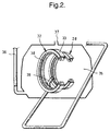
- each stator portion of the electromagnetic bearings 26, 28 and 32 is in the form of a ring 33 that carries an annular array of electromagnetic coils 34 on its radially inner surface.
- the coils 34 when activated, create a magnetic field that serves to support the shaft surrounded by the ring 33.
- the coils 34 when activated, generate heat.
- the electromagnetic bearings 28 and 32 are contained within a chamber 35 to which cooling air derived from a convenient source (such as one of the engine's compressors) is directed.
- the cooling air is delivered to the chamber 35 through a pipe 36 and exhausted from the chamber 35 through an outlet orifice 37. It will be appreciated that other forms of gas cooling could be employed if so desired and indeed it may be desirable in certain circumstances to employ liquid cooling.
- the electromagnetic bearings 26, 28 and 32 are actively controlled. This is to ensure that the shafts 18, 19 and 20 are maintained as closely as possible to a coaxial relationship with the longitudinal axis 10a of the engine 10. Additionally, the electromagnetic bearings 26, 28 and 32 are controlled in such a way that any vibration in the shafts 18, 19 and 20 is substantially eliminated.
- each electromagnetic bearing is associated with a plurality of sensors, one of which 38 can be seen in Figure 2, that provide output signals representative of the distance between each shaft and its corresponding electromagnetic bearing. If reference is now made to Figure 3, which shows the third electromagnetic bearing 32, the active control mechanism can be seen in more detail. It will be appreciated however that the remaining first and second electromagnetic bearings 26 and 28 are of similar configuration.
- the electromagnetic bearing 32 is surrounded by a plurality of the coils 34 carried, as mentioned previously, by the ring 33.
- the coils 34 carried, as mentioned previously, by the ring 33.
- Figure 3 only four coils 34 are shown, but it will be appreciated that as mentioned earlier, there is an annular array of such coils 34.
- two sensors 38 are shown, there are in fact more than this.
- the signals from a pair of diametrically opposed sensors 38 are fed to an device 40 that determines the difference between the signals and provides an output signal 41 proportional to that difference.
- the sensor difference output signal 41 is combined with a reference signal 42, whereupon the combined signal is acted upon by an analogue to digital converter 43.
- the resultant digital signal is then acted upon by a control device 44 which determines the nature of the magnetic field necessary to maintain the shaft 20 coaxial with the engine axis 10a.
- the output of the control device 44 is divided into two signals 45 and 46 that are acted upon by two digital to analogue converters 47 and 48.
- the resultant analogue signals are acted upon by two power amplifiers 49 and 50 before being directed to activate the coils 34 in a manner consistent with the maintenance of a coaxial relationship between the shaft 20 and engine axis 10a.
- the coils 34 and sensors 38 may also be activated in such a manner, as mentioned earlier, as to reduce or substantially eliminate vibration in the shaft 20.
- the first shaft 18 interconnecting the fan 11 and the low pressure turbine 17 is provided with an electrical generator 51 at its downstream end.
- the generator 51 which may be of any convenient type, generates electrical power upon the rotation of the first shaft 18.
- the generated electrical power provides two outputs 52 and 53.
- the first output 52 is directed to provide electrical power for the aircraft which in use carries the engine 10.
- the remaining electrical output 53 from the generator 51 is directed to the main electronic control unit 57 for the engine 10 and constitutes the power source for that unit 57.
- the control unit 57 in turn supplies an appropriate level of electrical power via a line 58 to the control unit 59 of the electromagnetic bearings 26, 28 and 32.
- the control unit 59 incorporates the circuitry shown in Figure 3 and other, similar, circuitry.
- the main electronic control unit 57 does, of course, also control the operation of many of the remaining variable features of the engine 10.
- the generator 51 is the primary source of power for the electromagnetic bearings 26, 28 and 32, it will be appreciated that in certain situations, such as during engine starting or during maintenance when the engine 10 is not running, insufficient power will be generated to activate the bearings. Under such circumstances, it will be necessary to derive electrical power from an alternative source, such as a battery, auxiliary power unit or other suitable power source.
- the electromagnetic bearings 26, 28 and 32 are all located within the hot turbine section of the engine 10. Since these bearings do not require an externally supplied liquid lubricant in order to function, problems usually associated with the provision of liquid lubricant passages within a hot engine area are avoided. Thus the problems of thermal degradation of lubricating oil and the resultant coking and lacquering problems that this can give rise to are avoided. Moreover, since the constraints of a liquid lubricated system are avoided, it is possible to contemplate increasing the operating temperatures within the turbine. This in turn gives rise to the possibility of increased thermal efficiency of the engine 10.
- the liquid lubrication system may be simplified, thereby reducing costs and weight.
- the rolling element bearings 24, 27, 29, 31 and 33 are located close to the air driven starter 60 used for starting the engine 10, they could utilise a liquid lubricant system shared with that starter 60.
- the starter 60 is mechanically interconnected with the third shaft 20 in the conventional manner via a bevel gear arrangement 65 in order to facilitate engine starting.
- the present invention has been described with specific reference to a gas turbine engine for use in powering an aircraft, it will be appreciated that it is also applicable to gas turbine engines used for other purposes. Thus, for instance the present invention may be applicable to gas turbine engines used in land-based power generation units or those used for marine purposes.
Landscapes
- Engineering & Computer Science (AREA)
- General Engineering & Computer Science (AREA)
- Mechanical Engineering (AREA)
- Chemical & Material Sciences (AREA)
- Combustion & Propulsion (AREA)
- Magnetic Bearings And Hydrostatic Bearings (AREA)
- Rolling Contact Bearings (AREA)
Applications Claiming Priority (2)
| Application Number | Priority Date | Filing Date | Title |
|---|---|---|---|
| GBGB9904221.0A GB9904221D0 (en) | 1999-02-25 | 1999-02-25 | Gas turbine engine bearing arrangement |
| GB9904221 | 1999-02-25 |
Publications (3)
| Publication Number | Publication Date |
|---|---|
| EP1031715A2 true EP1031715A2 (de) | 2000-08-30 |
| EP1031715A3 EP1031715A3 (de) | 2002-07-03 |
| EP1031715B1 EP1031715B1 (de) | 2005-08-24 |
Family
ID=10848396
Family Applications (1)
| Application Number | Title | Priority Date | Filing Date |
|---|---|---|---|
| EP00301185A Expired - Lifetime EP1031715B1 (de) | 1999-02-25 | 2000-02-16 | Lageranordnung in einer Gasturbine |
Country Status (4)
| Country | Link |
|---|---|
| US (1) | US6378293B1 (de) |
| EP (1) | EP1031715B1 (de) |
| DE (1) | DE60022108T2 (de) |
| GB (1) | GB9904221D0 (de) |
Cited By (15)
| Publication number | Priority date | Publication date | Assignee | Title |
|---|---|---|---|---|
| EP1312822A3 (de) * | 2001-11-10 | 2006-05-17 | Rolls-Royce Plc | Wellenlager |
| EP1352161A4 (de) * | 2000-12-22 | 2007-01-03 | Pratt & Whitney Canada | Hauptantriebstriebwerkssystem mit integriertem hilfsantriebsaggregat |
| EP1544416A3 (de) * | 2003-12-15 | 2007-02-28 | Man Turbo Ag | Lagerung des Rotors einer Gasturbine |
| US8100646B2 (en) | 2008-05-16 | 2012-01-24 | Rolls-Royce Deutschland Ltd & Co Kg | Two-shaft engine for an aircraft gas turbine |
| CN104481899A (zh) * | 2014-12-05 | 2015-04-01 | 浙江理工大学 | 采用电磁轴承的外转子离心风机 |
| CN109707513A (zh) * | 2018-12-10 | 2019-05-03 | 中国航发四川燃气涡轮研究院 | 一种多电发动机进气机匣 |
| US20210270209A1 (en) * | 2013-09-03 | 2021-09-02 | Israel Aerospace Industries Ltd. | Engine |
| US20220268205A1 (en) * | 2019-09-30 | 2022-08-25 | Ihi Corporation | Electric generator and multi-shaft gas turbine engine for aircraft equipped with electric generator |
| GB2610573A (en) * | 2021-09-08 | 2023-03-15 | Rolls Royce Plc | An improved gas turbine engine |
| US11920540B2 (en) | 2021-09-08 | 2024-03-05 | Rolls-Royce Plc | Gas turbine engine with a defined fan axis angle between a fan tip axis and a centerline |
| US11993387B2 (en) | 2021-09-08 | 2024-05-28 | Rolls-Royce Plc | Gas turbine engine |
| US12006055B2 (en) | 2021-09-08 | 2024-06-11 | Rolls-Royce Plc | Gas turbine engine with electric machines |
| US12092030B2 (en) | 2021-09-08 | 2024-09-17 | Rolls-Royce Plc | Gas turbine engine |
| US12092037B2 (en) | 2021-09-08 | 2024-09-17 | Rolls-Royce Plc | Gas turbine engine with electric machines |
| US12104530B2 (en) | 2021-09-08 | 2024-10-01 | Rolls-Royce Plc | Gas turbine engine |
Families Citing this family (31)
| Publication number | Priority date | Publication date | Assignee | Title |
|---|---|---|---|---|
| WO2003008792A1 (en) * | 2001-07-18 | 2003-01-30 | Jae-Chang Lee | Jet engine using exhaust gas |
| US6608418B2 (en) * | 2001-08-24 | 2003-08-19 | Smiths Aerospace, Inc. | Permanent magnet turbo-generator having magnetic bearings |
| US6881027B2 (en) * | 2003-02-18 | 2005-04-19 | Honeywell International, Inc. | Gearless/oilless gas turbine engine |
| US7055306B2 (en) | 2003-04-30 | 2006-06-06 | Hamilton Sundstrand Corporation | Combined stage single shaft turbofan engine |
| US7033133B2 (en) * | 2003-12-10 | 2006-04-25 | Honeywell International, Inc. | Air turbine starter having a low differential check valve |
| US7033134B2 (en) * | 2004-02-24 | 2006-04-25 | Honeywell International, Inc. | Air turbine starter having a force balanced, pressure energized, weighted check valve |
| US7014419B2 (en) * | 2004-02-27 | 2006-03-21 | Honeywell International, Inc. | Passive improved air turbine starter lubrication system |
| FR2878286B1 (fr) * | 2004-11-25 | 2009-05-22 | Snecma Moteurs Sa | Turbomachine comportant un generateur de courant electrique integre |
| US20060196164A1 (en) * | 2005-03-03 | 2006-09-07 | Donohue Thomas F | Dual mode turbo engine |
| DE102006003884A1 (de) * | 2006-01-27 | 2007-08-02 | Mtu Aero Engines Gmbh | Strahltriebwerk mit aktivmagnetischer Lagerung |
| US7750521B2 (en) * | 2006-12-07 | 2010-07-06 | General Electric Company | Double-sided starter/generator for aircrafts |
| US7765789B2 (en) * | 2006-12-15 | 2010-08-03 | General Electric Company | Apparatus and method for assembling gas turbine engines |
| US7950237B2 (en) * | 2007-06-25 | 2011-05-31 | United Technologies Corporation | Managing spool bearing load using variable area flow nozzle |
| FR2919896B1 (fr) * | 2007-08-07 | 2009-10-30 | Snecma Sa | Turboreacteur comprenant un generateur de courant monte dans la soufflante et un procede de montage dudit generateur dans la soufflante |
| US9494084B2 (en) | 2007-08-23 | 2016-11-15 | United Technologies Corporation | Gas turbine engine with fan variable area nozzle for low fan pressure ratio |
| US10167813B2 (en) | 2007-08-23 | 2019-01-01 | United Technologies Corporation | Gas turbine engine with fan variable area nozzle to reduce fan instability |
| US9701415B2 (en) | 2007-08-23 | 2017-07-11 | United Technologies Corporation | Gas turbine engine with axial movable fan variable area nozzle |
| US8028513B2 (en) * | 2007-10-26 | 2011-10-04 | United Technologies Corporation | Variable bypass turbine fan |
| DE102008018101A1 (de) * | 2008-04-09 | 2009-10-15 | Rolls-Royce Deutschland Ltd & Co Kg | Strahltriebwerk mit mindestens einem Notantrieb |
| DE102010049885B4 (de) * | 2010-11-01 | 2015-06-25 | Rolls-Royce Deutschland Ltd & Co Kg | Strahltriebwerk |
| AT510988B1 (de) * | 2011-03-03 | 2012-08-15 | Avl List Gmbh | Brennkraftmaschine |
| WO2013147951A1 (en) * | 2011-12-30 | 2013-10-03 | United Technologies Corporation | Gas turbine engine with fan variable area nozzle for low fan pressure ratio |
| US8607576B1 (en) * | 2012-06-07 | 2013-12-17 | United Technologies Corporation | Single turbine driving dual compressors |
| US9097134B2 (en) * | 2012-09-14 | 2015-08-04 | Pratt & Whitney Canada Corp. | Air cooling design for tail-cone generator installation |
| WO2014133836A1 (en) | 2013-02-28 | 2014-09-04 | United Technologies Corporation | Self cleaning debris filter for fan drive gear system |
| US9638056B2 (en) * | 2013-03-12 | 2017-05-02 | Rolls-Royce North American Technologies, Inc. | Gas turbine engine and active balancing system |
| GB201704502D0 (en) * | 2017-03-22 | 2017-05-03 | Rolls Royce Plc | Gas turbine engine |
| GB201718068D0 (en) * | 2017-11-01 | 2017-12-13 | Rolls Royce Plc | Resonance vibration control method and system |
| EP4092289A1 (de) * | 2021-05-17 | 2022-11-23 | Rolls-Royce Deutschland Ltd & Co KG | System zur schwingungskontrolle in drehmaschinen |
| US12473857B2 (en) * | 2023-04-21 | 2025-11-18 | Rtx Corporation | Magnetic-foil bearing supporting turbine engine rotating structure |
| CN120140414A (zh) * | 2023-12-11 | 2025-06-13 | 通用电气公司 | 用于燃气涡轮发动机的扭转振动阻尼器机构 |
Citations (1)
| Publication number | Priority date | Publication date | Assignee | Title |
|---|---|---|---|---|
| EP0816654A2 (de) | 1996-06-26 | 1998-01-07 | Allison Engine Company, Inc. | Lagerkombination für eine Gasturbine |
Family Cites Families (12)
| Publication number | Priority date | Publication date | Assignee | Title |
|---|---|---|---|---|
| US3907386A (en) * | 1973-01-22 | 1975-09-23 | Avco Corp | Bearing assembly systems |
| DE3527945A1 (de) * | 1985-08-03 | 1987-02-12 | Bbc Brown Boveri & Cie | Lagerung von rotierenden maschinen |
| US5355042A (en) * | 1988-09-09 | 1994-10-11 | University Of Virginia Patent Foundation | Magnetic bearings for pumps, compressors and other rotating machinery |
| JPH04124496A (ja) * | 1990-09-17 | 1992-04-24 | Hitachi Ltd | 流体機械 |
| GB2258699A (en) | 1991-08-10 | 1993-02-17 | Rolls Royce Business Ventures | Shaft bearing arrangement |
| GB2268983B (en) * | 1992-07-23 | 1996-04-03 | Glacier Metal Co Ltd | Magnetic bearing back-up |
| DE9215696U1 (de) * | 1992-11-18 | 1994-03-17 | Anton Piller GmbH & Co KG, 37520 Osterode | Stromgewinnungsanlage |
| US5376827A (en) * | 1993-05-27 | 1994-12-27 | General Electric Company | Integrated turbine-generator |
| DE4444587A1 (de) * | 1994-12-14 | 1996-06-20 | Siemens Ag | Turbine mit einer magnetisch gelagerten Welle |
| US5658125A (en) | 1995-02-28 | 1997-08-19 | Allison Engine Company, Inc. | Magnetic bearings as actuation for active compressor stability control |
| GB9606546D0 (en) * | 1996-03-28 | 1996-06-05 | Rolls Royce Plc | Gas turbine engine system |
| US5749700A (en) * | 1996-07-17 | 1998-05-12 | Allison Engine Company, Inc. | High speed, high temperature hybrid magnetic thrust bearing |
-
1999
- 1999-02-25 GB GBGB9904221.0A patent/GB9904221D0/en not_active Ceased
-
2000
- 2000-02-16 DE DE60022108T patent/DE60022108T2/de not_active Expired - Lifetime
- 2000-02-16 EP EP00301185A patent/EP1031715B1/de not_active Expired - Lifetime
- 2000-02-18 US US09/506,570 patent/US6378293B1/en not_active Expired - Lifetime
Patent Citations (1)
| Publication number | Priority date | Publication date | Assignee | Title |
|---|---|---|---|---|
| EP0816654A2 (de) | 1996-06-26 | 1998-01-07 | Allison Engine Company, Inc. | Lagerkombination für eine Gasturbine |
Cited By (19)
| Publication number | Priority date | Publication date | Assignee | Title |
|---|---|---|---|---|
| EP1352161A4 (de) * | 2000-12-22 | 2007-01-03 | Pratt & Whitney Canada | Hauptantriebstriebwerkssystem mit integriertem hilfsantriebsaggregat |
| EP1312822A3 (de) * | 2001-11-10 | 2006-05-17 | Rolls-Royce Plc | Wellenlager |
| EP1544416A3 (de) * | 2003-12-15 | 2007-02-28 | Man Turbo Ag | Lagerung des Rotors einer Gasturbine |
| US8100646B2 (en) | 2008-05-16 | 2012-01-24 | Rolls-Royce Deutschland Ltd & Co Kg | Two-shaft engine for an aircraft gas turbine |
| US11629666B2 (en) * | 2013-09-03 | 2023-04-18 | Israel Aerospace Industries Ltd. | Turbofan engine |
| US20210270209A1 (en) * | 2013-09-03 | 2021-09-02 | Israel Aerospace Industries Ltd. | Engine |
| CN104481899A (zh) * | 2014-12-05 | 2015-04-01 | 浙江理工大学 | 采用电磁轴承的外转子离心风机 |
| CN109707513A (zh) * | 2018-12-10 | 2019-05-03 | 中国航发四川燃气涡轮研究院 | 一种多电发动机进气机匣 |
| CN109707513B (zh) * | 2018-12-10 | 2021-11-26 | 中国航发四川燃气涡轮研究院 | 一种多电发动机进气机匣 |
| US20220268205A1 (en) * | 2019-09-30 | 2022-08-25 | Ihi Corporation | Electric generator and multi-shaft gas turbine engine for aircraft equipped with electric generator |
| US11867119B2 (en) * | 2019-09-30 | 2024-01-09 | Ihi Corporation | Electric generator and multi-shaft gas turbine engine for aircraft equipped with electric generator |
| EP4148247A1 (de) * | 2021-09-08 | 2023-03-15 | Rolls-Royce plc | Verbesserter gasturbinenmotor |
| GB2610573A (en) * | 2021-09-08 | 2023-03-15 | Rolls Royce Plc | An improved gas turbine engine |
| US11920540B2 (en) | 2021-09-08 | 2024-03-05 | Rolls-Royce Plc | Gas turbine engine with a defined fan axis angle between a fan tip axis and a centerline |
| US11993387B2 (en) | 2021-09-08 | 2024-05-28 | Rolls-Royce Plc | Gas turbine engine |
| US12006055B2 (en) | 2021-09-08 | 2024-06-11 | Rolls-Royce Plc | Gas turbine engine with electric machines |
| US12092030B2 (en) | 2021-09-08 | 2024-09-17 | Rolls-Royce Plc | Gas turbine engine |
| US12092037B2 (en) | 2021-09-08 | 2024-09-17 | Rolls-Royce Plc | Gas turbine engine with electric machines |
| US12104530B2 (en) | 2021-09-08 | 2024-10-01 | Rolls-Royce Plc | Gas turbine engine |
Also Published As
| Publication number | Publication date |
|---|---|
| DE60022108D1 (de) | 2005-09-29 |
| GB9904221D0 (en) | 1999-04-21 |
| US6378293B1 (en) | 2002-04-30 |
| DE60022108T2 (de) | 2006-02-16 |
| EP1031715B1 (de) | 2005-08-24 |
| EP1031715A3 (de) | 2002-07-03 |
Similar Documents
| Publication | Publication Date | Title |
|---|---|---|
| EP1031715B1 (de) | Lageranordnung in einer Gasturbine | |
| EP1706620B1 (de) | Turbomotorarchitektur | |
| US7703290B2 (en) | Air thrust bearing for a gas turbine engine | |
| US7065954B2 (en) | Turbine, particularly useful for small aircraft | |
| US5113670A (en) | Bearing cooling arrangement for air cycle machine | |
| US3722212A (en) | Gas turbine engine lubrication system | |
| EP2935840B1 (de) | Halterung mit einer axialen aufwärtsverbindung zum verbinden eines getriebes mit einem turbinenmotorgehäuse | |
| EP3536901B1 (de) | Schubsteuerung eines gelagerten rotors | |
| US20060108807A1 (en) | Turbomachine including an integrated electricity generator | |
| CN110878760B (zh) | 用于涡轮机械的密封组件 | |
| US12065972B2 (en) | Buffer fluid delivery system and method for a shaft seal of a gas turbine engine | |
| CN104136721B (zh) | 涡轮发动机及其操作方法 | |
| EP4015852B1 (de) | Lagergehäuse mit gleitgelenk | |
| EP4345269B1 (de) | Wärmeverwaltungssystem für flugzeuge | |
| US11834991B2 (en) | Lubrication system for turbine engine electric machine | |
| US12270342B1 (en) | Thermal management system for an engine | |
| US20250003482A1 (en) | Lubrication system for a gear assembly | |
| EP4484801A1 (de) | Schmiersystem für eine getriebeanordnung | |
| US9540952B2 (en) | Turbocharger with oil-free hydrostatic bearing |
Legal Events
| Date | Code | Title | Description |
|---|---|---|---|
| PUAI | Public reference made under article 153(3) epc to a published international application that has entered the european phase |
Free format text: ORIGINAL CODE: 0009012 |
|
| AK | Designated contracting states |
Kind code of ref document: A2 Designated state(s): AT BE CH CY DE DK ES FI FR GB GR IE IT LI LU MC NL PT SE |
|
| AX | Request for extension of the european patent |
Free format text: AL;LT;LV;MK;RO;SI |
|
| PUAL | Search report despatched |
Free format text: ORIGINAL CODE: 0009013 |
|
| AK | Designated contracting states |
Kind code of ref document: A3 Designated state(s): AT BE CH CY DE DK ES FI FR GB GR IE IT LI LU MC NL PT SE |
|
| AX | Request for extension of the european patent |
Free format text: AL;LT;LV;MK;RO;SI |
|
| 17P | Request for examination filed |
Effective date: 20020629 |
|
| AKX | Designation fees paid |
Designated state(s): DE FR GB |
|
| 17Q | First examination report despatched |
Effective date: 20030227 |
|
| GRAP | Despatch of communication of intention to grant a patent |
Free format text: ORIGINAL CODE: EPIDOSNIGR1 |
|
| GRAS | Grant fee paid |
Free format text: ORIGINAL CODE: EPIDOSNIGR3 |
|
| GRAA | (expected) grant |
Free format text: ORIGINAL CODE: 0009210 |
|
| AK | Designated contracting states |
Kind code of ref document: B1 Designated state(s): DE FR GB |
|
| REG | Reference to a national code |
Ref country code: GB Ref legal event code: FG4D |
|
| REF | Corresponds to: |
Ref document number: 60022108 Country of ref document: DE Date of ref document: 20050929 Kind code of ref document: P |
|
| ET | Fr: translation filed | ||
| PLBE | No opposition filed within time limit |
Free format text: ORIGINAL CODE: 0009261 |
|
| STAA | Information on the status of an ep patent application or granted ep patent |
Free format text: STATUS: NO OPPOSITION FILED WITHIN TIME LIMIT |
|
| 26N | No opposition filed |
Effective date: 20060526 |
|
| PGFP | Annual fee paid to national office [announced via postgrant information from national office to epo] |
Ref country code: GB Payment date: 20130227 Year of fee payment: 14 Ref country code: FR Payment date: 20130311 Year of fee payment: 14 Ref country code: DE Payment date: 20130227 Year of fee payment: 14 |
|
| REG | Reference to a national code |
Ref country code: DE Ref legal event code: R119 Ref document number: 60022108 Country of ref document: DE |
|
| GBPC | Gb: european patent ceased through non-payment of renewal fee |
Effective date: 20140216 |
|
| REG | Reference to a national code |
Ref country code: FR Ref legal event code: ST Effective date: 20141031 |
|
| REG | Reference to a national code |
Ref country code: DE Ref legal event code: R119 Ref document number: 60022108 Country of ref document: DE Effective date: 20140902 |
|
| PG25 | Lapsed in a contracting state [announced via postgrant information from national office to epo] |
Ref country code: FR Free format text: LAPSE BECAUSE OF NON-PAYMENT OF DUE FEES Effective date: 20140228 Ref country code: GB Free format text: LAPSE BECAUSE OF NON-PAYMENT OF DUE FEES Effective date: 20140216 Ref country code: DE Free format text: LAPSE BECAUSE OF NON-PAYMENT OF DUE FEES Effective date: 20140902 |