EP1031782A2 - Demi-tube - Google Patents
Demi-tube Download PDFInfo
- Publication number
- EP1031782A2 EP1031782A2 EP00103660A EP00103660A EP1031782A2 EP 1031782 A2 EP1031782 A2 EP 1031782A2 EP 00103660 A EP00103660 A EP 00103660A EP 00103660 A EP00103660 A EP 00103660A EP 1031782 A2 EP1031782 A2 EP 1031782A2
- Authority
- EP
- European Patent Office
- Prior art keywords
- pipe shell
- projections
- pipe
- insulation
- shell according
- Prior art date
- Legal status (The legal status is an assumption and is not a legal conclusion. Google has not performed a legal analysis and makes no representation as to the accuracy of the status listed.)
- Withdrawn
Links
- 238000009413 insulation Methods 0.000 claims abstract description 56
- 239000011490 mineral wool Substances 0.000 claims abstract description 11
- 239000000835 fiber Substances 0.000 claims abstract description 8
- 229920002522 Wood fibre Polymers 0.000 claims abstract description 4
- 229920002678 cellulose Polymers 0.000 claims abstract description 4
- 239000001913 cellulose Substances 0.000 claims abstract description 4
- 239000000919 ceramic Substances 0.000 claims abstract description 4
- 239000007799 cork Substances 0.000 claims abstract description 4
- 239000011491 glass wool Substances 0.000 claims abstract description 4
- 239000002557 mineral fiber Substances 0.000 claims abstract description 4
- 239000002023 wood Substances 0.000 claims abstract description 4
- 239000002025 wood fiber Substances 0.000 claims abstract description 4
- 210000002268 wool Anatomy 0.000 claims abstract description 4
- 239000000378 calcium silicate Substances 0.000 claims abstract description 3
- 229910052918 calcium silicate Inorganic materials 0.000 claims abstract description 3
- OYACROKNLOSFPA-UHFFFAOYSA-N calcium;dioxido(oxo)silane Chemical compound [Ca+2].[O-][Si]([O-])=O OYACROKNLOSFPA-UHFFFAOYSA-N 0.000 claims abstract description 3
- 239000010451 perlite Substances 0.000 claims abstract description 3
- 235000019362 perlite Nutrition 0.000 claims abstract description 3
- 239000004033 plastic Substances 0.000 claims abstract description 3
- 229920003023 plastic Polymers 0.000 claims abstract description 3
- 239000004575 stone Substances 0.000 claims description 23
- 239000000779 smoke Substances 0.000 claims description 15
- 239000002803 fossil fuel Substances 0.000 claims description 5
- 239000007789 gas Substances 0.000 claims description 5
- 238000010438 heat treatment Methods 0.000 claims description 5
- 239000006260 foam Substances 0.000 claims description 2
- 239000011494 foam glass Substances 0.000 claims description 2
- 238000002485 combustion reaction Methods 0.000 claims 2
- 239000011449 brick Substances 0.000 abstract 1
- 239000011521 glass Substances 0.000 abstract 1
- 238000005253 cladding Methods 0.000 description 6
- 239000000463 material Substances 0.000 description 5
- 238000005452 bending Methods 0.000 description 3
- 230000000694 effects Effects 0.000 description 3
- 239000004793 Polystyrene Substances 0.000 description 2
- 230000015572 biosynthetic process Effects 0.000 description 2
- 238000009434 installation Methods 0.000 description 2
- 238000004519 manufacturing process Methods 0.000 description 2
- 208000000260 Warts Diseases 0.000 description 1
- 230000006978 adaptation Effects 0.000 description 1
- 239000011230 binding agent Substances 0.000 description 1
- 229910010293 ceramic material Inorganic materials 0.000 description 1
- 230000006835 compression Effects 0.000 description 1
- 238000007906 compression Methods 0.000 description 1
- 238000010276 construction Methods 0.000 description 1
- 239000004570 mortar (masonry) Substances 0.000 description 1
- 238000000465 moulding Methods 0.000 description 1
- 229920002223 polystyrene Polymers 0.000 description 1
- 201000010153 skin papilloma Diseases 0.000 description 1
Images

Classifications
-
- F—MECHANICAL ENGINEERING; LIGHTING; HEATING; WEAPONS; BLASTING
- F16—ENGINEERING ELEMENTS AND UNITS; GENERAL MEASURES FOR PRODUCING AND MAINTAINING EFFECTIVE FUNCTIONING OF MACHINES OR INSTALLATIONS; THERMAL INSULATION IN GENERAL
- F16L—PIPES; JOINTS OR FITTINGS FOR PIPES; SUPPORTS FOR PIPES, CABLES OR PROTECTIVE TUBING; MEANS FOR THERMAL INSULATION IN GENERAL
- F16L59/00—Thermal insulation in general
- F16L59/02—Shape or form of insulating materials, with or without coverings integral with the insulating materials
- F16L59/021—Shape or form of insulating materials, with or without coverings integral with the insulating materials comprising a single piece or sleeve, e.g. split sleeves; consisting of two half sleeves; comprising more than two segments
- F16L59/025—Shape or form of insulating materials, with or without coverings integral with the insulating materials comprising a single piece or sleeve, e.g. split sleeves; consisting of two half sleeves; comprising more than two segments comprising more than two segments
Definitions
- the invention relates to a pipe shell for thermal and / or acoustic insulation a pipeline, in particular a pipeline for the discharge of when burning fossil fuels in heating systems resulting exhaust gases, with at least one insulation element, the two in has essentially large surfaces running parallel to each other, at least one surface of which is on a lateral surface of an adjacent one Component, in particular on the outer surface of the pipe to be insulated and / or on an inner surface of a the tubular element surrounding the casing stone lies.
- the invention further relates to the use of a pipe shell with at least an insulation element, the two substantially parallel to each other has large surfaces.
- tubular shells are known from the prior art. They exist from one or more insulation boards that have a certain bending ability have so that they match the radius of curvature of a pipe can be adjusted. Such pipe shells are also for pipelines with a deviating from a circular cross-section Cross section, for example a polygonal cross section can be used.
- the pipe shells described above are used in particular Thermal insulation of three-shell chimneys consisting of a flue pipe, an insulation layer and cladding stones.
- Smoke pipe which consists of stacked pipe sections, arranged within the mantle stones. Between the coat stones and the pipe sections of the smoke pipe, which also in the rest can be formed in one piece, insulation elements are arranged, the for example made of mineral wool, in particular rock wool and form the pipe shell.
- the smoke pipe consists in particular of coarse ceramic materials, such as chamotte and can be round or essentially cross-section be polygonal, the edges of one in cross section polygonal smoke pipe made of fluidic and are rounded off for technical reasons.
- the assembly this chimney is done in such a way that first mantle stones under Use mortar on top of each other.
- the number of out Shorter stones due to weight depends on the length of the Smoke pipe segments, d. H. the pipe shots, which are interposed the insulation elements are arranged in the cladding stones.
- the the Pipe shell forming insulation elements support the smoke pipe against the Sheath stone from and must be fitted exactly, so that a complete Thermal insulation is achieved that is not due to discontinuities in the area of the insulation elements, d. H. between neighboring insulation elements is affected.
- Such insulation elements usually have a material thickness of 3 to 5 cm, so that this is relative thin plates. Due to the high coefficient of friction of the Insulation on the surface of the mantle stone or the surface of the Flue pipe can damage the insulation elements. It is also possible that the high coefficient of friction is a compression caused the inserted insulation elements, so that neighboring The edges of insulation elements should not lie completely on top of each other. Furthermore there is a risk that the thin insulation panels will bend, so that areas arise between the mantle stone and the flue pipe are not adequately insulated because of open joints at the joints of the boards clearly shows the thermal resistance of the insulation layer to reduce.
- DE 196 16 268 U1 is an insulation element that has proven itself in practice for thermal insulation of polygonal cross-section Pipelines known. It also describes the AT-PS 319 453 the formation of a pipe shell, which is in a space between adjacent components, for example one Flue pipe and a casing stone can be arranged. More examples related pipe shells are from US 3,336,951, the DE 82 32 124 U1 and DE-OS 25 08 733 known.
- the invention has for its object to provide a generic pipe shell that can be used in various ways with different pipes, especially fireplace systems and compensates for manufacturing tolerances, ensuring a tight fit of the pipe shell, in particular between two adjacent components.
- projections are arranged in the area of at least one surface.
- the insulation element points to the formation of the pipe shell in the area at least one surface protrudes slightly from it highlight the surface.
- These projections support the clamping effect the pipe shell, especially between the casing stones and the smoke pipe.
- friction force occurring in the area of the projections having reduced surface of the insulation element.
- the manufacturing tolerances are the same as both Insulating element, as well as the pipeline to be insulated or with it connected system components.
- the protrusions are compressible trained so that a pressure stress when installing the pipe shell between the insulation element and the neighboring component is built, it ensures that the pipe shell during the Installation of the component does not slide out of this.
- the projections at equal distances from each other on the surface of the Insulation element are arranged.
- an arrangement of the Insulation element at a constant distance from the neighboring component guaranteed so that the advantages described above overall over the entire surface of the insulation element or the pipe shell remain.
- the distance between the insulation element and the component can also be made very small in order to avoid unnecessary Avoid airspaces that reduce the insulation performance.
- the projections are strip-shaped and extend in particular parallel to a longitudinal edge of the insulation element. But it is also conceivable that the projections are wart-shaped and distributed over the surface of the insulation element or the pipe shell are.
- Corresponding insulation element on side surfaces running parallel to each other has trained gradations. These gradations are formed such that the insulating element in the region of its side surfaces is plugged into one another with a continuous pipe shell to achieve constant insulation properties.
- the Projections arranged in the area of the gradations which is particularly true has proven to be advantageous if the pipe shell consists of several insulation elements formed in this way. Usually are such insulation elements are the same, so that the projections at equal distances from each other over the circumference of the Pipe shell are arranged distributed.
- the projections are arranged on both surfaces of the insulating element. It has proven to be advantageous that the positive overall Effects of the pipe shell can be further improved.
- the projections are semicircular in cross section, so that on the one hand they are linear or point-shaped on the lateral surfaces of the or adjacent components and on the other hand by the shape have good compressibility.
- the projections have a triangular cross section are trained. This configuration is particularly then advantageous if the projections in the area of the gradations of the Insulation elements are arranged.
- the pipe shell can consist of several insulation elements exist, which are plate-shaped and a certain bending stiffness have an adaptation of the insulation elements to the required Radius of the pipe shell allows. Form the insulation elements thus sections of the pipe shell and can be assembled to form the pipe shell.
- the insulating element or elements from mineral fibers in particular glass, slag and / or Rock wool, from ceramic fibers, from foam plastics, such as EPS, FEF, PEF, PF, PUR, PIR and / or UF and / or made of foam glass, calcium silicate, Cork, wood fibers, wood wool, cellulose and / or expanded perlite and / or the like exists.
- foam plastics such as EPS, FEF, PEF, PF, PUR, PIR and / or UF and / or made of foam glass, calcium silicate, Cork, wood fibers, wood wool, cellulose and / or expanded perlite and / or the like exists.
- the pipe shell according to the invention can be round, oval or other Way arcuate and / or polygonal, in particular rectangular or square pipes are used.
- this pipe shell is according to the invention Thermal and / or acoustic insulation of a pipeline for the discharge of when burning fossil fuels in heating systems Exhaust gases are provided, the pipe shell between a smoke pipe and a cladding stone is arranged.
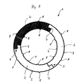
- Figure 1 is a first embodiment of a pipe shell 1 in cross section shown.
- the pipe shell 1 consists of three plate-shaped Insulating elements 2, which have a certain bending stiffness, so that them to the diameter of an insulated, not shown Pipeline are customizable.
- the three insulation elements 2 form a total the tubular shell 1 in cross section, so that the tubular shell 1 for Thermal and / or acoustic insulation of a chimney can be used, which has a smoke pipe and casing stones, not shown, which are arranged at a distance from the flue pipe so that the pipe shell 1 an annular cavity between the mantle stones and the Fills the smoke pipe.
- Each insulation element 2 has two large ones running parallel to one another Surfaces 3, 4 and two narrow sides running in the longitudinal direction 5, 6 on
- the large surface 4 forms an inner lateral surface and the large surface 3 an outer surface of the pipe shell 1, the large surface 3 on the inner surface of the casing stone and the large surface 4 on the outer surface of the smoke tube is present.
- the narrow sides 5, 6 are provided with a gradation 7 that Adjacent insulation elements 2 can be positively connected to one another and in total a tube shell 1 with a homogeneous material thickness is created.
- the step 7 in the area of the narrow side 5 is approximately staircase-shaped or Z-shaped, so that a step is formed into which a section of the adjacent insulation element 2 can be used.
- the insulation elements 2 consist of mineral fibers, namely rock wool fibers, designed in the usual way to a flat insulation element and are bound with binders.
- the insulation elements 2 in evenly spaced projections on the are semicircular in cross section.
- the protrusions 8 are ledge-shaped and extend in the longitudinal direction of the pipe shell 1 over almost the entire surface 3, 4 of the insulation element 2. It can also be seen that the projections 8 in the embodiment according to Figure 1 essentially opposite in the area the surfaces 3, 4 are arranged.
- FIG. 2 shows a second embodiment of a pipe shell 1, which corresponds structurally essentially to the pipe shell 1 according to FIG. 1.
- the difference between the two pipe shells 1 in the Figures 1 and 2 is that in the embodiment according to Figure 2 projections 9 are arranged in the region of the gradations 7.
- the Projections 9 are triangular in cross section and extend also strip-like in the longitudinal direction of the pipe shell 1. How in the case of the projections 8 according to FIG linear contact of the projections 9 on the not shown Mantle stone of a fireplace.
- both the semicircular as well as triangular shape of the projections 8, 9 advantageous in terms of the compressibility of the projections 8, 9, which are made of the same material as the insulation element 2 exist.
- the pipe shells 1 described above are particularly suitable for use in heat and / or sound insulation Pipeline for the discharge of fossil fuels Exhaust gases generated in heating systems, the Pipe shell 1 arranged between a smoke pipe and a casing stone becomes.
- the pipe shell 1 shown here is for a cross section round smoke pipe and a casing stone with a round pipe opening in cross section intended.
- the projections 8, 9 simultaneously reduce the frictional forces, that occur when the pipe shell 1 in a cavity between Cladding stone and flue pipe is inserted.
- This montage can be done either at the factory or at the construction site, with the projections 8, 9 have the advantage that the Pipe shell 1 through the projections 8, 9 improved in the cavity between the smoke pipe and the cladding stone is held.
- the tabs 8, 9 are compressible so that they build up a certain compressive stress, with which the advantages described above can be achieved.
- the pipe shell 1 can of course also consist of other materials, if the pipe shell 1 for example in low temperature applications can be made from foamed moldings. In addition to rock wool fibers Glass wool fibers, ceramic fibers, Find slag wool fibers and / or molded polystyrene parts. Of course there is also the possibility of the pipe shell 1 Form cork, wood fibers, wood wool, cellulose or the like, wherein the use of the pipe shell 1 according to the invention not on the area shown is limited in chimney systems.
Landscapes
- Engineering & Computer Science (AREA)
- General Engineering & Computer Science (AREA)
- Mechanical Engineering (AREA)
- Thermal Insulation (AREA)
- Exhaust Silencers (AREA)
- Rigid Pipes And Flexible Pipes (AREA)
Applications Claiming Priority (2)
| Application Number | Priority Date | Filing Date | Title |
|---|---|---|---|
| DE1999108673 DE19908673A1 (de) | 1999-02-26 | 1999-02-26 | Rohrschale |
| DE19908673 | 1999-02-26 |
Publications (2)
| Publication Number | Publication Date |
|---|---|
| EP1031782A2 true EP1031782A2 (fr) | 2000-08-30 |
| EP1031782A3 EP1031782A3 (fr) | 2003-04-09 |
Family
ID=7899175
Family Applications (1)
| Application Number | Title | Priority Date | Filing Date |
|---|---|---|---|
| EP00103660A Withdrawn EP1031782A3 (fr) | 1999-02-26 | 2000-02-22 | Demi-tube |
Country Status (2)
| Country | Link |
|---|---|
| EP (1) | EP1031782A3 (fr) |
| DE (1) | DE19908673A1 (fr) |
Cited By (6)
| Publication number | Priority date | Publication date | Assignee | Title |
|---|---|---|---|---|
| EP1184614A3 (fr) * | 2000-08-29 | 2003-03-12 | Deutsche Rockwool Mineralwoll GmbH & Co. OHG | Demi-coquille |
| EP1559844A1 (fr) * | 2004-01-31 | 2005-08-03 | Deutsche Rockwool Mineralwoll GmbH & Co. OHG | Element d' isolation et système composite d' isolation thermique |
| EP1571404A1 (fr) * | 2004-03-05 | 2005-09-07 | Wolf GmbH | Accumulateur stratifié avec un carter et une isolation |
| EP1610050A1 (fr) * | 2004-06-25 | 2005-12-28 | Deutsche Rockwool Mineralwoll GmbH & Co. OHG | Elément d'isolation de tuyau pour l'isolation thermique et/ou acoustique d'un tuyau |
| EP2876347A1 (fr) * | 2013-11-22 | 2015-05-27 | Saint-Gobain Isover G+H Ag | Élément d'isolation thermique ou acoustique de conduits, en particulier de conduits de cheminée |
| US9790836B2 (en) | 2012-11-20 | 2017-10-17 | Tenneco Automotive Operating Company, Inc. | Loose-fill insulation exhaust gas treatment device and methods of manufacturing |
Families Citing this family (5)
| Publication number | Priority date | Publication date | Assignee | Title |
|---|---|---|---|---|
| DE10228001A1 (de) * | 2002-06-22 | 2004-01-15 | Deutsche Rockwool Mineralwoll Gmbh + Co Ohg | Vorrichtung zur Führung und Ausleitung von Abluft |
| DE102011107573A1 (de) | 2011-07-16 | 2013-06-06 | Secura Services Ag | Thermisch isolierende Rohrschelle |
| CN104406008A (zh) * | 2014-11-04 | 2015-03-11 | 北京市燃气集团有限责任公司 | 聚乙烯燃气管道的保温隔热设施及其隔热方法 |
| DE202016004919U1 (de) | 2016-08-11 | 2016-09-05 | Saint-Gobain Isover G+H Ag | Dämmsystem für in Mantelsteinen geführte Kaminrohre |
| CN113266730B (zh) * | 2021-06-21 | 2021-11-19 | 江苏金环科技有限公司 | 一种具有补偿功能的保温装置 |
Citations (11)
| Publication number | Priority date | Publication date | Assignee | Title |
|---|---|---|---|---|
| DE1225929B (de) * | 1964-07-22 | 1966-09-29 | Emil Siegwart | Verfahren zum Aufbringen einer Berbund-isolierung auf insbesondere von Wasser oder Dampf durchstroemte und gegen Waermeverlust zu schuetzende Rohrleitungen und Vorrichtung dazu |
| US3336951A (en) | 1964-04-27 | 1967-08-22 | Eagle Picher Co | Grooved insulating material |
| DE2309866A1 (de) * | 1972-03-02 | 1973-09-06 | Rockwool Ab | Rohrschalung |
| AT319453B (de) | 1971-04-14 | 1974-12-27 | Schiedel Kamin Betonwerk | Schacht, insbesondere Kamin- oder Abwurfschacht |
| US3886981A (en) * | 1971-11-08 | 1975-06-03 | Atlantic Richfield Co | Pipeline insulation means |
| DE2508733A1 (de) | 1974-03-01 | 1976-02-05 | Strulik Wilhelm P | Waerme- und schalldaemmender mantel fuer lueftungs- und klimaanlagen |
| DE8232127U1 (de) | 1982-11-16 | 1983-06-30 | Felten & Guilleaume Energietechnik GmbH, 5000 Köln | Kraftschluessiger abschluss einer flexiblen fernwaermeleitung |
| FR2556447A1 (fr) * | 1983-12-08 | 1985-06-14 | Thimon Jacques | Element tubulaire pour cheminee |
| DE29520476U1 (de) * | 1995-12-23 | 1996-02-08 | Hewing Gmbh | Isolierung für ein Sanitär- oder Heizungsrohr |
| DE29518110U1 (de) * | 1995-11-15 | 1996-11-28 | Achenbach GmbH & Co. KG, 57548 Kirchen | Wärmeisolierende Körper-Ummantelung |
| DE19616268A1 (de) | 1996-04-24 | 1997-11-06 | Rockwool Mineralwolle | Vorrichtung zur Führung und Ausleitung von Verbrennungsgasen sowie Herstellungsverfahren |
Family Cites Families (3)
| Publication number | Priority date | Publication date | Assignee | Title |
|---|---|---|---|---|
| GB8814014D0 (en) * | 1988-06-14 | 1988-07-20 | British Petroleum Co Plc | Insulating material |
| KR920006734Y1 (ko) * | 1990-02-07 | 1992-09-26 | 이종호 | 내경면에 나선상의 유체 삼각 안내돌기를 갖는 다층 파이프 |
| DE4110124C2 (de) * | 1991-03-27 | 2002-02-21 | Missel Gmbh & Co E | Verfahren zur Anbringung eines schlauchförmigen Verbundes an einem Abwasserrohr mit verbesserter Schalldämmung |
-
1999
- 1999-02-26 DE DE1999108673 patent/DE19908673A1/de not_active Ceased
-
2000
- 2000-02-22 EP EP00103660A patent/EP1031782A3/fr not_active Withdrawn
Patent Citations (11)
| Publication number | Priority date | Publication date | Assignee | Title |
|---|---|---|---|---|
| US3336951A (en) | 1964-04-27 | 1967-08-22 | Eagle Picher Co | Grooved insulating material |
| DE1225929B (de) * | 1964-07-22 | 1966-09-29 | Emil Siegwart | Verfahren zum Aufbringen einer Berbund-isolierung auf insbesondere von Wasser oder Dampf durchstroemte und gegen Waermeverlust zu schuetzende Rohrleitungen und Vorrichtung dazu |
| AT319453B (de) | 1971-04-14 | 1974-12-27 | Schiedel Kamin Betonwerk | Schacht, insbesondere Kamin- oder Abwurfschacht |
| US3886981A (en) * | 1971-11-08 | 1975-06-03 | Atlantic Richfield Co | Pipeline insulation means |
| DE2309866A1 (de) * | 1972-03-02 | 1973-09-06 | Rockwool Ab | Rohrschalung |
| DE2508733A1 (de) | 1974-03-01 | 1976-02-05 | Strulik Wilhelm P | Waerme- und schalldaemmender mantel fuer lueftungs- und klimaanlagen |
| DE8232127U1 (de) | 1982-11-16 | 1983-06-30 | Felten & Guilleaume Energietechnik GmbH, 5000 Köln | Kraftschluessiger abschluss einer flexiblen fernwaermeleitung |
| FR2556447A1 (fr) * | 1983-12-08 | 1985-06-14 | Thimon Jacques | Element tubulaire pour cheminee |
| DE29518110U1 (de) * | 1995-11-15 | 1996-11-28 | Achenbach GmbH & Co. KG, 57548 Kirchen | Wärmeisolierende Körper-Ummantelung |
| DE29520476U1 (de) * | 1995-12-23 | 1996-02-08 | Hewing Gmbh | Isolierung für ein Sanitär- oder Heizungsrohr |
| DE19616268A1 (de) | 1996-04-24 | 1997-11-06 | Rockwool Mineralwolle | Vorrichtung zur Führung und Ausleitung von Verbrennungsgasen sowie Herstellungsverfahren |
Cited By (6)
| Publication number | Priority date | Publication date | Assignee | Title |
|---|---|---|---|---|
| EP1184614A3 (fr) * | 2000-08-29 | 2003-03-12 | Deutsche Rockwool Mineralwoll GmbH & Co. OHG | Demi-coquille |
| EP1559844A1 (fr) * | 2004-01-31 | 2005-08-03 | Deutsche Rockwool Mineralwoll GmbH & Co. OHG | Element d' isolation et système composite d' isolation thermique |
| EP1571404A1 (fr) * | 2004-03-05 | 2005-09-07 | Wolf GmbH | Accumulateur stratifié avec un carter et une isolation |
| EP1610050A1 (fr) * | 2004-06-25 | 2005-12-28 | Deutsche Rockwool Mineralwoll GmbH & Co. OHG | Elément d'isolation de tuyau pour l'isolation thermique et/ou acoustique d'un tuyau |
| US9790836B2 (en) | 2012-11-20 | 2017-10-17 | Tenneco Automotive Operating Company, Inc. | Loose-fill insulation exhaust gas treatment device and methods of manufacturing |
| EP2876347A1 (fr) * | 2013-11-22 | 2015-05-27 | Saint-Gobain Isover G+H Ag | Élément d'isolation thermique ou acoustique de conduits, en particulier de conduits de cheminée |
Also Published As
| Publication number | Publication date |
|---|---|
| DE19908673A1 (de) | 2000-09-07 |
| EP1031782A3 (fr) | 2003-04-09 |
Similar Documents
| Publication | Publication Date | Title |
|---|---|---|
| DE3635270C2 (fr) | ||
| DE102008055978A1 (de) | Platten-Unterbau zum flächigen Verlegen von Rohrleitungen für Heiz- Kühl- oder Absorberzwecke, zum Beispiel für Fußboden- oder Wandheizungen sowie Verfahren zur Herstellung einer solchen Heizung | |
| DE19908673A1 (de) | Rohrschale | |
| DE2902831A1 (de) | Schall- und waermeisolationswand | |
| DE10039859A1 (de) | Leitungsbauteil für Lüftungsrohre oder -kanäle | |
| DE2003139A1 (de) | Rohrleitung aus Kunststoff fuer gasfoermige Medien | |
| DE3546735C2 (de) | Dämmplatte zur Wärmedämmung von Rohren, bestehend aus Mineralfasern | |
| DE3040116A1 (de) | Rohrfoermiger leitungskanal fuer installationszwecke | |
| DE69312025T2 (de) | Multischalen-Element mit flexiblen Isolierplatten zwischen den Wänden von diesem Element | |
| EP0551640A1 (fr) | Revêtement pour mur de bâtiment | |
| DE19509890C1 (de) | Schornstein-Dämmelement | |
| DE19616268C2 (de) | Vorrichtung zur Führung und Ausleitung von durch eine, in einem Gebäude zu Heizzwecken installierte Verbrennungseinrichtung | |
| AT404630B (de) | Dämmelement | |
| EP1610050B1 (fr) | Elément d'isolation de tuyau pour l'isolation thermique et/ou acoustique d'un tuyau | |
| DE8803395U1 (de) | Rohr | |
| DE29701757U1 (de) | Asymetrisch genutete Mineralfaserdämmplatten, vorzugsweise für Wärmedämmung runder Rauchrohre von Schornsteinen und Abgasanlagen | |
| DE10000803A1 (de) | Schacht für Schornsteine oder Abgasleitungen | |
| EP1301668B1 (fr) | Element constitutif | |
| AT13130U1 (de) | Rauchgaszugsystem, rauchgaszugmodul und nachheizvorrichtung | |
| DE29624218U1 (de) | Vorrichtung zur Führung und Ausleitung von Verbrennungsgasen | |
| DE3705725A1 (de) | Mehrschaliger isolierschacht | |
| EP1058057A1 (fr) | Elément de cheminée avec amenée d'air de combustion | |
| DE9409804U1 (de) | Rohrleitungsisolation | |
| DE3517996A1 (de) | Feuchtigkeitsunempfindlicher hausschornstein | |
| DE10042254A1 (de) | Rohrschale |
Legal Events
| Date | Code | Title | Description |
|---|---|---|---|
| PUAI | Public reference made under article 153(3) epc to a published international application that has entered the european phase |
Free format text: ORIGINAL CODE: 0009012 |
|
| AK | Designated contracting states |
Kind code of ref document: A2 Designated state(s): AT BE CH CY DE DK ES FI FR GB GR IE IT LI LU MC NL PT SE |
|
| AX | Request for extension of the european patent |
Free format text: AL;LT;LV;MK;RO;SI |
|
| RAP1 | Party data changed (applicant data changed or rights of an application transferred) |
Owner name: DEUTSCHE ROCKWOOL MINERALWOLL GMBH & CO. OHG |
|
| PUAL | Search report despatched |
Free format text: ORIGINAL CODE: 0009013 |
|
| AK | Designated contracting states |
Kind code of ref document: A3 Designated state(s): AT BE CH CY DE DK ES FI FR GB GR IE IT LI LU MC NL PT SE Designated state(s): AT BE CH CY DE DK ES FI FR GB GR IE IT LI LU MC NL PT SE |
|
| AX | Request for extension of the european patent |
Extension state: AL LT LV MK RO SI |
|
| 17P | Request for examination filed |
Effective date: 20030329 |
|
| AKX | Designation fees paid |
Designated state(s): DE |
|
| 17Q | First examination report despatched |
Effective date: 20040303 |
|
| STAA | Information on the status of an ep patent application or granted ep patent |
Free format text: STATUS: THE APPLICATION IS DEEMED TO BE WITHDRAWN |
|
| 18D | Application deemed to be withdrawn |
Effective date: 20050301 |