EP1031803B1 - Verfahren und Vorrichtung zur Maximierung der Produktivität einer Erdgasverflüssigungsanlage - Google Patents
Verfahren und Vorrichtung zur Maximierung der Produktivität einer Erdgasverflüssigungsanlage Download PDFInfo
- Publication number
- EP1031803B1 EP1031803B1 EP00400475A EP00400475A EP1031803B1 EP 1031803 B1 EP1031803 B1 EP 1031803B1 EP 00400475 A EP00400475 A EP 00400475A EP 00400475 A EP00400475 A EP 00400475A EP 1031803 B1 EP1031803 B1 EP 1031803B1
- Authority
- EP
- European Patent Office
- Prior art keywords
- valve
- recompressor
- compressor
- turboexpander
- antisurge
- Prior art date
- Legal status (The legal status is an assumption and is not a legal conclusion. Google has not performed a legal analysis and makes no representation as to the accuracy of the status listed.)
- Expired - Lifetime
Links
- VNWKTOKETHGBQD-UHFFFAOYSA-N methane Chemical compound C VNWKTOKETHGBQD-UHFFFAOYSA-N 0.000 title claims description 30
- 238000000034 method Methods 0.000 title claims description 24
- 239000003345 natural gas Substances 0.000 title claims description 15
- 239000007788 liquid Substances 0.000 title claims description 13
- 238000004519 manufacturing process Methods 0.000 title claims description 10
- 238000005259 measurement Methods 0.000 claims description 9
- 230000007423 decrease Effects 0.000 claims description 8
- 239000007789 gas Substances 0.000 description 11
- 230000009471 action Effects 0.000 description 3
- 238000010586 diagram Methods 0.000 description 3
- 230000008901 benefit Effects 0.000 description 2
- 239000000446 fuel Substances 0.000 description 2
- 230000008569 process Effects 0.000 description 2
- 238000012545 processing Methods 0.000 description 2
- 238000004364 calculation method Methods 0.000 description 1
- 238000004891 communication Methods 0.000 description 1
- 230000006835 compression Effects 0.000 description 1
- 238000007906 compression Methods 0.000 description 1
- 238000012986 modification Methods 0.000 description 1
- 230000004048 modification Effects 0.000 description 1
- 238000012544 monitoring process Methods 0.000 description 1
- 238000000926 separation method Methods 0.000 description 1
- 230000009466 transformation Effects 0.000 description 1
Images


Classifications
-
- F—MECHANICAL ENGINEERING; LIGHTING; HEATING; WEAPONS; BLASTING
- F25—REFRIGERATION OR COOLING; COMBINED HEATING AND REFRIGERATION SYSTEMS; HEAT PUMP SYSTEMS; MANUFACTURE OR STORAGE OF ICE; LIQUEFACTION SOLIDIFICATION OF GASES
- F25J—LIQUEFACTION, SOLIDIFICATION OR SEPARATION OF GASES OR GASEOUS OR LIQUEFIED GASEOUS MIXTURES BY PRESSURE AND COLD TREATMENT OR BY BRINGING THEM INTO THE SUPERCRITICAL STATE
- F25J3/00—Processes or apparatus for separating the constituents of gaseous or liquefied gaseous mixtures involving the use of liquefaction or solidification
- F25J3/02—Processes or apparatus for separating the constituents of gaseous or liquefied gaseous mixtures involving the use of liquefaction or solidification by rectification, i.e. by continuous interchange of heat and material between a vapour stream and a liquid stream
- F25J3/0295—Start-up or control of the process; Details of the apparatus used, e.g. sieve plates, packings
-
- F—MECHANICAL ENGINEERING; LIGHTING; HEATING; WEAPONS; BLASTING
- F01—MACHINES OR ENGINES IN GENERAL; ENGINE PLANTS IN GENERAL; STEAM ENGINES
- F01D—NON-POSITIVE DISPLACEMENT MACHINES OR ENGINES, e.g. STEAM TURBINES
- F01D15/00—Adaptations of machines or engines for special use; Combinations of engines with devices driven thereby
- F01D15/08—Adaptations for driving, or combinations with, pumps
-
- F—MECHANICAL ENGINEERING; LIGHTING; HEATING; WEAPONS; BLASTING
- F02—COMBUSTION ENGINES; HOT-GAS OR COMBUSTION-PRODUCT ENGINE PLANTS
- F02C—GAS-TURBINE PLANTS; AIR INTAKES FOR JET-PROPULSION PLANTS; CONTROLLING FUEL SUPPLY IN AIR-BREATHING JET-PROPULSION PLANTS
- F02C1/00—Gas-turbine plants characterised by the use of hot gases or unheated pressurised gases, as the working fluid
- F02C1/02—Gas-turbine plants characterised by the use of hot gases or unheated pressurised gases, as the working fluid the working fluid being an unheated pressurised gas
-
- F—MECHANICAL ENGINEERING; LIGHTING; HEATING; WEAPONS; BLASTING
- F25—REFRIGERATION OR COOLING; COMBINED HEATING AND REFRIGERATION SYSTEMS; HEAT PUMP SYSTEMS; MANUFACTURE OR STORAGE OF ICE; LIQUEFACTION SOLIDIFICATION OF GASES
- F25J—LIQUEFACTION, SOLIDIFICATION OR SEPARATION OF GASES OR GASEOUS OR LIQUEFIED GASEOUS MIXTURES BY PRESSURE AND COLD TREATMENT OR BY BRINGING THEM INTO THE SUPERCRITICAL STATE
- F25J3/00—Processes or apparatus for separating the constituents of gaseous or liquefied gaseous mixtures involving the use of liquefaction or solidification
- F25J3/02—Processes or apparatus for separating the constituents of gaseous or liquefied gaseous mixtures involving the use of liquefaction or solidification by rectification, i.e. by continuous interchange of heat and material between a vapour stream and a liquid stream
- F25J3/0204—Processes or apparatus for separating the constituents of gaseous or liquefied gaseous mixtures involving the use of liquefaction or solidification by rectification, i.e. by continuous interchange of heat and material between a vapour stream and a liquid stream characterised by the feed stream
- F25J3/0209—Natural gas or substitute natural gas
-
- F—MECHANICAL ENGINEERING; LIGHTING; HEATING; WEAPONS; BLASTING
- F25—REFRIGERATION OR COOLING; COMBINED HEATING AND REFRIGERATION SYSTEMS; HEAT PUMP SYSTEMS; MANUFACTURE OR STORAGE OF ICE; LIQUEFACTION SOLIDIFICATION OF GASES
- F25J—LIQUEFACTION, SOLIDIFICATION OR SEPARATION OF GASES OR GASEOUS OR LIQUEFIED GASEOUS MIXTURES BY PRESSURE AND COLD TREATMENT OR BY BRINGING THEM INTO THE SUPERCRITICAL STATE
- F25J3/00—Processes or apparatus for separating the constituents of gaseous or liquefied gaseous mixtures involving the use of liquefaction or solidification
- F25J3/02—Processes or apparatus for separating the constituents of gaseous or liquefied gaseous mixtures involving the use of liquefaction or solidification by rectification, i.e. by continuous interchange of heat and material between a vapour stream and a liquid stream
- F25J3/0228—Processes or apparatus for separating the constituents of gaseous or liquefied gaseous mixtures involving the use of liquefaction or solidification by rectification, i.e. by continuous interchange of heat and material between a vapour stream and a liquid stream characterised by the separated product stream
- F25J3/0233—Processes or apparatus for separating the constituents of gaseous or liquefied gaseous mixtures involving the use of liquefaction or solidification by rectification, i.e. by continuous interchange of heat and material between a vapour stream and a liquid stream characterised by the separated product stream separation of CnHm with 1 carbon atom or more
-
- F—MECHANICAL ENGINEERING; LIGHTING; HEATING; WEAPONS; BLASTING
- F25—REFRIGERATION OR COOLING; COMBINED HEATING AND REFRIGERATION SYSTEMS; HEAT PUMP SYSTEMS; MANUFACTURE OR STORAGE OF ICE; LIQUEFACTION SOLIDIFICATION OF GASES
- F25J—LIQUEFACTION, SOLIDIFICATION OR SEPARATION OF GASES OR GASEOUS OR LIQUEFIED GASEOUS MIXTURES BY PRESSURE AND COLD TREATMENT OR BY BRINGING THEM INTO THE SUPERCRITICAL STATE
- F25J3/00—Processes or apparatus for separating the constituents of gaseous or liquefied gaseous mixtures involving the use of liquefaction or solidification
- F25J3/02—Processes or apparatus for separating the constituents of gaseous or liquefied gaseous mixtures involving the use of liquefaction or solidification by rectification, i.e. by continuous interchange of heat and material between a vapour stream and a liquid stream
- F25J3/0228—Processes or apparatus for separating the constituents of gaseous or liquefied gaseous mixtures involving the use of liquefaction or solidification by rectification, i.e. by continuous interchange of heat and material between a vapour stream and a liquid stream characterised by the separated product stream
- F25J3/0238—Processes or apparatus for separating the constituents of gaseous or liquefied gaseous mixtures involving the use of liquefaction or solidification by rectification, i.e. by continuous interchange of heat and material between a vapour stream and a liquid stream characterised by the separated product stream separation of CnHm with 2 carbon atoms or more
-
- F—MECHANICAL ENGINEERING; LIGHTING; HEATING; WEAPONS; BLASTING
- F25—REFRIGERATION OR COOLING; COMBINED HEATING AND REFRIGERATION SYSTEMS; HEAT PUMP SYSTEMS; MANUFACTURE OR STORAGE OF ICE; LIQUEFACTION SOLIDIFICATION OF GASES
- F25J—LIQUEFACTION, SOLIDIFICATION OR SEPARATION OF GASES OR GASEOUS OR LIQUEFIED GASEOUS MIXTURES BY PRESSURE AND COLD TREATMENT OR BY BRINGING THEM INTO THE SUPERCRITICAL STATE
- F25J3/00—Processes or apparatus for separating the constituents of gaseous or liquefied gaseous mixtures involving the use of liquefaction or solidification
- F25J3/02—Processes or apparatus for separating the constituents of gaseous or liquefied gaseous mixtures involving the use of liquefaction or solidification by rectification, i.e. by continuous interchange of heat and material between a vapour stream and a liquid stream
- F25J3/0228—Processes or apparatus for separating the constituents of gaseous or liquefied gaseous mixtures involving the use of liquefaction or solidification by rectification, i.e. by continuous interchange of heat and material between a vapour stream and a liquid stream characterised by the separated product stream
- F25J3/0242—Processes or apparatus for separating the constituents of gaseous or liquefied gaseous mixtures involving the use of liquefaction or solidification by rectification, i.e. by continuous interchange of heat and material between a vapour stream and a liquid stream characterised by the separated product stream separation of CnHm with 3 carbon atoms or more
-
- F—MECHANICAL ENGINEERING; LIGHTING; HEATING; WEAPONS; BLASTING
- F25—REFRIGERATION OR COOLING; COMBINED HEATING AND REFRIGERATION SYSTEMS; HEAT PUMP SYSTEMS; MANUFACTURE OR STORAGE OF ICE; LIQUEFACTION SOLIDIFICATION OF GASES
- F25J—LIQUEFACTION, SOLIDIFICATION OR SEPARATION OF GASES OR GASEOUS OR LIQUEFIED GASEOUS MIXTURES BY PRESSURE AND COLD TREATMENT OR BY BRINGING THEM INTO THE SUPERCRITICAL STATE
- F25J3/00—Processes or apparatus for separating the constituents of gaseous or liquefied gaseous mixtures involving the use of liquefaction or solidification
- F25J3/06—Processes or apparatus for separating the constituents of gaseous or liquefied gaseous mixtures involving the use of liquefaction or solidification by partial condensation
- F25J3/0605—Processes or apparatus for separating the constituents of gaseous or liquefied gaseous mixtures involving the use of liquefaction or solidification by partial condensation characterised by the feed stream
- F25J3/061—Natural gas or substitute natural gas
-
- F—MECHANICAL ENGINEERING; LIGHTING; HEATING; WEAPONS; BLASTING
- F25—REFRIGERATION OR COOLING; COMBINED HEATING AND REFRIGERATION SYSTEMS; HEAT PUMP SYSTEMS; MANUFACTURE OR STORAGE OF ICE; LIQUEFACTION SOLIDIFICATION OF GASES
- F25J—LIQUEFACTION, SOLIDIFICATION OR SEPARATION OF GASES OR GASEOUS OR LIQUEFIED GASEOUS MIXTURES BY PRESSURE AND COLD TREATMENT OR BY BRINGING THEM INTO THE SUPERCRITICAL STATE
- F25J3/00—Processes or apparatus for separating the constituents of gaseous or liquefied gaseous mixtures involving the use of liquefaction or solidification
- F25J3/06—Processes or apparatus for separating the constituents of gaseous or liquefied gaseous mixtures involving the use of liquefaction or solidification by partial condensation
- F25J3/063—Processes or apparatus for separating the constituents of gaseous or liquefied gaseous mixtures involving the use of liquefaction or solidification by partial condensation characterised by the separated product stream
- F25J3/0635—Processes or apparatus for separating the constituents of gaseous or liquefied gaseous mixtures involving the use of liquefaction or solidification by partial condensation characterised by the separated product stream separation of CnHm with 1 carbon atom or more
-
- F—MECHANICAL ENGINEERING; LIGHTING; HEATING; WEAPONS; BLASTING
- F25—REFRIGERATION OR COOLING; COMBINED HEATING AND REFRIGERATION SYSTEMS; HEAT PUMP SYSTEMS; MANUFACTURE OR STORAGE OF ICE; LIQUEFACTION SOLIDIFICATION OF GASES
- F25J—LIQUEFACTION, SOLIDIFICATION OR SEPARATION OF GASES OR GASEOUS OR LIQUEFIED GASEOUS MIXTURES BY PRESSURE AND COLD TREATMENT OR BY BRINGING THEM INTO THE SUPERCRITICAL STATE
- F25J3/00—Processes or apparatus for separating the constituents of gaseous or liquefied gaseous mixtures involving the use of liquefaction or solidification
- F25J3/06—Processes or apparatus for separating the constituents of gaseous or liquefied gaseous mixtures involving the use of liquefaction or solidification by partial condensation
- F25J3/063—Processes or apparatus for separating the constituents of gaseous or liquefied gaseous mixtures involving the use of liquefaction or solidification by partial condensation characterised by the separated product stream
- F25J3/064—Processes or apparatus for separating the constituents of gaseous or liquefied gaseous mixtures involving the use of liquefaction or solidification by partial condensation characterised by the separated product stream separation of CnHm with 2 carbon atoms or more
-
- F—MECHANICAL ENGINEERING; LIGHTING; HEATING; WEAPONS; BLASTING
- F25—REFRIGERATION OR COOLING; COMBINED HEATING AND REFRIGERATION SYSTEMS; HEAT PUMP SYSTEMS; MANUFACTURE OR STORAGE OF ICE; LIQUEFACTION SOLIDIFICATION OF GASES
- F25J—LIQUEFACTION, SOLIDIFICATION OR SEPARATION OF GASES OR GASEOUS OR LIQUEFIED GASEOUS MIXTURES BY PRESSURE AND COLD TREATMENT OR BY BRINGING THEM INTO THE SUPERCRITICAL STATE
- F25J3/00—Processes or apparatus for separating the constituents of gaseous or liquefied gaseous mixtures involving the use of liquefaction or solidification
- F25J3/06—Processes or apparatus for separating the constituents of gaseous or liquefied gaseous mixtures involving the use of liquefaction or solidification by partial condensation
- F25J3/063—Processes or apparatus for separating the constituents of gaseous or liquefied gaseous mixtures involving the use of liquefaction or solidification by partial condensation characterised by the separated product stream
- F25J3/0645—Processes or apparatus for separating the constituents of gaseous or liquefied gaseous mixtures involving the use of liquefaction or solidification by partial condensation characterised by the separated product stream separation of CnHm with 3 carbon atoms or more
-
- F—MECHANICAL ENGINEERING; LIGHTING; HEATING; WEAPONS; BLASTING
- F25—REFRIGERATION OR COOLING; COMBINED HEATING AND REFRIGERATION SYSTEMS; HEAT PUMP SYSTEMS; MANUFACTURE OR STORAGE OF ICE; LIQUEFACTION SOLIDIFICATION OF GASES
- F25J—LIQUEFACTION, SOLIDIFICATION OR SEPARATION OF GASES OR GASEOUS OR LIQUEFIED GASEOUS MIXTURES BY PRESSURE AND COLD TREATMENT OR BY BRINGING THEM INTO THE SUPERCRITICAL STATE
- F25J2230/00—Processes or apparatus involving steps for increasing the pressure of gaseous process streams
- F25J2230/20—Integrated compressor and process expander; Gear box arrangement; Multiple compressors on a common shaft
-
- F—MECHANICAL ENGINEERING; LIGHTING; HEATING; WEAPONS; BLASTING
- F25—REFRIGERATION OR COOLING; COMBINED HEATING AND REFRIGERATION SYSTEMS; HEAT PUMP SYSTEMS; MANUFACTURE OR STORAGE OF ICE; LIQUEFACTION SOLIDIFICATION OF GASES
- F25J—LIQUEFACTION, SOLIDIFICATION OR SEPARATION OF GASES OR GASEOUS OR LIQUEFIED GASEOUS MIXTURES BY PRESSURE AND COLD TREATMENT OR BY BRINGING THEM INTO THE SUPERCRITICAL STATE
- F25J2230/00—Processes or apparatus involving steps for increasing the pressure of gaseous process streams
- F25J2230/32—Compression of the product stream
-
- F—MECHANICAL ENGINEERING; LIGHTING; HEATING; WEAPONS; BLASTING
- F25—REFRIGERATION OR COOLING; COMBINED HEATING AND REFRIGERATION SYSTEMS; HEAT PUMP SYSTEMS; MANUFACTURE OR STORAGE OF ICE; LIQUEFACTION SOLIDIFICATION OF GASES
- F25J—LIQUEFACTION, SOLIDIFICATION OR SEPARATION OF GASES OR GASEOUS OR LIQUEFIED GASEOUS MIXTURES BY PRESSURE AND COLD TREATMENT OR BY BRINGING THEM INTO THE SUPERCRITICAL STATE
- F25J2230/00—Processes or apparatus involving steps for increasing the pressure of gaseous process streams
- F25J2230/60—Processes or apparatus involving steps for increasing the pressure of gaseous process streams the fluid being hydrocarbons or a mixture of hydrocarbons
-
- F—MECHANICAL ENGINEERING; LIGHTING; HEATING; WEAPONS; BLASTING
- F25—REFRIGERATION OR COOLING; COMBINED HEATING AND REFRIGERATION SYSTEMS; HEAT PUMP SYSTEMS; MANUFACTURE OR STORAGE OF ICE; LIQUEFACTION SOLIDIFICATION OF GASES
- F25J—LIQUEFACTION, SOLIDIFICATION OR SEPARATION OF GASES OR GASEOUS OR LIQUEFIED GASEOUS MIXTURES BY PRESSURE AND COLD TREATMENT OR BY BRINGING THEM INTO THE SUPERCRITICAL STATE
- F25J2240/00—Processes or apparatus involving steps for expanding of process streams
- F25J2240/02—Expansion of a process fluid in a work-extracting turbine (i.e. isentropic expansion), e.g. of the feed stream
-
- F—MECHANICAL ENGINEERING; LIGHTING; HEATING; WEAPONS; BLASTING
- F25—REFRIGERATION OR COOLING; COMBINED HEATING AND REFRIGERATION SYSTEMS; HEAT PUMP SYSTEMS; MANUFACTURE OR STORAGE OF ICE; LIQUEFACTION SOLIDIFICATION OF GASES
- F25J—LIQUEFACTION, SOLIDIFICATION OR SEPARATION OF GASES OR GASEOUS OR LIQUEFIED GASEOUS MIXTURES BY PRESSURE AND COLD TREATMENT OR BY BRINGING THEM INTO THE SUPERCRITICAL STATE
- F25J2240/00—Processes or apparatus involving steps for expanding of process streams
- F25J2240/80—Hot exhaust gas turbine combustion engine
-
- F—MECHANICAL ENGINEERING; LIGHTING; HEATING; WEAPONS; BLASTING
- F25—REFRIGERATION OR COOLING; COMBINED HEATING AND REFRIGERATION SYSTEMS; HEAT PUMP SYSTEMS; MANUFACTURE OR STORAGE OF ICE; LIQUEFACTION SOLIDIFICATION OF GASES
- F25J—LIQUEFACTION, SOLIDIFICATION OR SEPARATION OF GASES OR GASEOUS OR LIQUEFIED GASEOUS MIXTURES BY PRESSURE AND COLD TREATMENT OR BY BRINGING THEM INTO THE SUPERCRITICAL STATE
- F25J2280/00—Control of the process or apparatus
- F25J2280/02—Control in general, load changes, different modes ("runs"), measurements
Definitions
- This invention relates generally to a method and apparatus for maximizing the production rate of natural gas liquids (NGL) in a gas processing plant. More specifically, this invention relates to the control of a turboexpander that drives a recompressor, with the objective of maximizing NGL production.
- NGL natural gas liquids
- R c is a pressure ratio
- p d is a compressor discharge pressure
- p s is a compressor suction pressure
- ⁇ p o is a differential pressure obtained across a flow measurement device
- a location of the compressor's operation point may be determined relative to a surge limit line.
- the compressor's performance curves may also be plotted in a space defined by ( q red , h red ).
- a purpose of this invention is to maximize the production rate of NGL in a gas processing plant by increasing the power that the turboexpander absorbs. This can be achieved at maximum rotational speed and with maximum opening of the turboexpander's adjustable nozzles by opening the recompressor's antisurge (hot recycle) valve or its cold recycle valve, or both of them. Valve opening must be limited to a preset value determined by a curve constructed on the recompressor's performance map. This curve is located such that
- the invention is not limited to these forms of error calculation.
- Figs. 1A and 1B depict similar control system diagrams of a turbomachinery train used for natural gas liquids (NGL) separation.
- the train in each figure includes a turboexpander 101 with governed (adjustable) nozzles 103 , a separator 105 , a recompressor 107 having an antisurge (hot recycle) valve 109 , a booster compressor 111 having an antisurge (hot recycle) valve 113 , and a gas turbine 115 equipped with a fuel control valve 117 .
- the booster compressor 111 discharges to the plant outlet piping by way of a gas cooler 119 which, in turn, connects to the recompressor 107 inlet through a cold recycle valve 121 .
- the turboexpander 101 and both compressors 107, 111 are each equipped with a control system that includes devices for monitoring process input signals, such as pressures in suction and discharge, temperatures, rotational speed, and differential pressure across flow measurement devices. These process signals are sent by various transmitters: pressure (PT), temperature (TT), rotational speed (ST), and pressure differential flow measurement (FT- ⁇ p o ).
- process input signals such as pressures in suction and discharge, temperatures, rotational speed, and differential pressure across flow measurement devices. These process signals are sent by various transmitters: pressure (PT), temperature (TT), rotational speed (ST), and pressure differential flow measurement (FT- ⁇ p o ).
- FT- ⁇ p o pressure differential flow measurement
- the turbomachinery train shown in Fig. 1B includes the same transmitter types, but with the addition of a recompressor's differential pressure transmitter (DPT- ⁇ p o ) rather than two pressure transmitters (PT).
- System controllers (each equipped with a PID algorithm) consist of flow indicating (FIC) 123 , speed indicating (SIC) 125 , antisurge (UIC-1, 2) 127, 131 , cold recycle indicating (CRIC) 129 , and pressure indicating (PIC) 133 .
- FID flow indicating
- SIC speed indicating
- UICC antisurge
- CRIC cold recycle indicating
- PIC pressure indicating
- the apparatus operates in the following manner. Mass flow is maintained by adjustable nozzles 103 , while plant discharge pressure is maintained by the booster compressor 111 driven by the gas turbine 115 . Energy is removed from gas as it passes through the turboexpander 101 ; the gas then moves on to the separator 105 where high-molecular weight liquefied components are separated from the lighter gaseous components. Simultaneously, as the liquid level reaches a preset value, a separator level controller (not shown) opens a drain valve.
- the gas throughput controller (FIC) 123 opens the adjustable nozzles 103 by way of a summation block, ⁇ -1 135 . Because of this action, gas throughput and rotational speed of the turboexpander 101 increase. Consequently, the booster compressor's 111 rotational speed and the plant outlet pressure both decrease. At this time, an outlet pressure controller (PIC) 133 opens the fuel control valve 117 , thereby increasing the booster compressor's rotational speed and maintaining the plant outlet pressure equal to its set point.
- PIC outlet pressure controller
- the UIC-1 controller 127 and the CRIC controller 129 are both designed to maintain a minimum flow.
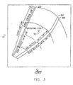
- the UIC-1 controller 127 modulates the hot recycle valve 113 to keep the operating point 301 (see Fig. 3 ) to the right of the surge control line 303 .
- the CRIC controller 129 modulates the cold recycle valve 121 to ensure that the operating point resides to the right of the cold recycle valve line 305 .
- the action of the CRIC controller also permits the hot recycle valve 113 to be closed (for antisurge purposes) in steady state to protect the recompressor 107 from high temperatures. Under a hard disturbance, both the hot recycle valve 113 and the cold recycle valve 121 may be opened to protect the recompressor from surge.
- UIC-1 127 and CRIC 129 An additional limiting loop is available in each of the two controllers, UIC-1 127 and CRIC 129 . These limiting loops are high-flow limits.
- the UIC-1 high-flow limit is intended to maintain the operating point to the left of the hot recycle valve limit line 307 by limiting the hot recycle valve's 113 opening.
- the CRIC high-flow limit is intended to maintain the operating point to the left of the cold recycle valve limit line 309 by limiting the opening of the cold recycle valve 121 .
- the relative positions of the hot and cold recycle valve limit lines 307, 309 ensures that the hot valve is closed first.
- this controller opens the recompressor's hot recycle valve 109 by way of summation block ⁇ -2 137 , or it opens the cold recycle valve 121 by way of summation block ⁇ -3 139 , or both operations concurrently. Opening the hot recycle valve 109 and/or the cold recycle valve 121 increases recompressor 107 power and, in turn, limits the turboexpander's rotational speed. Both valves may also open in a given relationship to prevent an increase of the recompressor's 107 inlet temperature.
- the UIC-1 controller 127 and the CRIC controller 129 stop increasing their respective output signals, thereby preventing further opening of the hot recycle valve 109 and/or the cold recycle valve 121.
- the SIC controller 125 cannot open the hot recycle valve 109 and/or the cold recycle valve 121 , and has to commence closing the adjustable nozzles 103 (acting through ⁇ -1 135 ) to limit the turboexpander's rotational speed.
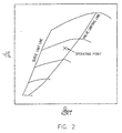
- the reason behind this sequence is that further opening of the hot and/or cold recycle valves 109 , 121 will not increase compressor power but, instead, will decrease power. This is shown in Fig. 2 where operation to the right of the curve labeled "Valve Limiting Line" will result in a decrease in compressor power with valve opening. Only the closing of the adjustable nozzles 103 can limit turboexpander rotational speed.
- the apparatus In carrying out the process by the previously described second method where both the cold recycle controller and the antisurge controller (whose set point may be slightly closer to the surge limit line) open corresponding valves to maintain maximum compressor power for the current rotational speed, the apparatus operates in the following manner. Summation blocks ⁇ -2, 3 137, 139 have zero multipliers on inputs from the SIC controller 125 . Set points for the UIC-1 controller 127 and the CRIC controller 129 are adjusted to slightly different high-flow limit set points. The compressor's maximum-power operating condition is now maintained at any rotational speed by opening the cold recycle valve 121 and the recompressor's hot recycle valve 109 , when needed.
- the high-flow set point of the UIC-1 controller is closer (as mentioned above) to the surge limit line than the high-flow set point of the CRIC controller, and the hot recycle valve 109 may be closed because the cold recycle valve 121 is sufficiently open and maintains the required compressor operating condition.
- the "Valve Limiting Line” shown in Fig. 2 is the "Hot Recycle Valve Limit Line” shown in Fig. 3 .
- a coordinate transformation is performed to plot it in coordinates which include only information available from measurement devices around the compressor.
- the compressor achieves its maximum power.
- the CRIC controller 129 and the cold recycle valve 121 may be recognized, to some extent, as an antisurge controller and an antisurge valve, respectively.
Landscapes
- Engineering & Computer Science (AREA)
- Mechanical Engineering (AREA)
- General Engineering & Computer Science (AREA)
- Physics & Mathematics (AREA)
- Thermal Sciences (AREA)
- Chemical & Material Sciences (AREA)
- Chemical Kinetics & Catalysis (AREA)
- General Chemical & Material Sciences (AREA)
- Oil, Petroleum & Natural Gas (AREA)
- Combustion & Propulsion (AREA)
- Control Of Positive-Displacement Air Blowers (AREA)
- Structures Of Non-Positive Displacement Pumps (AREA)
Claims (24)
- Verfahren zur Maximierung der Produktion von Erdgasflüssigkeiten aus Erdgas unter Verwendung einer Ausrüstung umfassend einen Turboexpander (101) mit einstellbaren Düsen (103), einen Rekompressor (107), einen Turboexpander - Geschwindigkeitsregler (125), eine Fließratensteuerung (123), eine Kompressor-Gegenverdichter-Regelung (127) und ein Kompressor-Gegenverdichter-Ventil (109, 121,), wobei das Verfahren umfasst:a) Messen einer Rotationsgeschwindigkeit N des Turboexpanders (101);b) Berechnung einer Abweichung N-NSP der Turboexpander-Rotationsgeschwindigkeit N von einem Begrenzungs-Sollwert NSP;c) Regelung der Rotationsgeschwindigkeit des Turboexpanders (101), wenn die Abweichung positiv ist, durch Modulation des Kompressor-Gegenverdichter-Ventils (109, 121), um die Abweichung auf einen Wert zurückzuführen und zu halten, der geringer oder gleich Null ist;d) Begrenzung der Öffnung des Kompressor-Gegenverdichter-Ventils (109, 121), wenn eine weitere Öffnung zu einer Abnahme der Kompressorleistung führt.
- Verfahren nach Anspruch 1, wobei die Bestimmung des Punktes, an dem eine weitere Öffnung des Gegenverdichter-Ventils (109, 121) zu einer Abnahme der Kompressorleistung führt, die Schritte umfasst:a) Messung von Parametern in der Nähe des Rekompressors (107), die geeignet sind für die Berechnung von ausgewählten Ähnlichkeitsparametern;b) Berechnung eines Rekompressors (107) - Arbeitspunktortes als eine Funktion der ausgewählten Ähnlichkeitsparameter unter Verwendung der gemessenen Parameter;c) Vergleich des Arbeitspunktortes mit einer vorbestimmten Grenze.
- Verfahren nach Anspruch 2, wobei die Öffnung des Gegenverdichter-Ventils (109, 121) angehalten wird, wenn der Arbeitspunkt an die vorbestimmte Grenze gelangt.
- Verfahren nach Anspruch 2, wobei die gemessenen Parameter, die in der Nähe des Rekompressors (107) gemessen werden, umfassen:a) einen Differentialdruck Δp0, gemessen über einer Fluss-Messeinrichtung;b) einen Ansaugdruck, ps; undc) einen Abgabedruck pd.
- Verfahren nach Anspruch 2, wobei die gemessenen Parameter, die in der Nähe des Rekompressors gemessen werden, umfassen:a) einen Differentialdruck Δp0, gemessen über einer Fluss-Messeinrichtung; undb) einen Differenzialdruck Δpc über dem Rekompressor (107).
- Verfahren nach Anspruch 1, wobei die einstellbaren Düsen (103) des Turboexpanders ebenfalls betätigt werden, um die Rotationsgeschwindigkeit N geringer oder gleich groß wie den Begrenzungs-Sollwert Nsp zu halten.
- Verfahren nach Anspruch 6, wobei die einstellbaren Düsen (103) des Turboexpanders betätigt werden, um die Rotationsgeschwindigkeit unter ihrem Grenzwert zu regeln, wenn die Öffnung des Gegenverdichter-Ventils begrenzt ist.
- Verfahren nach Anspruch 1, wobei das Kompressor-Gegenverdichter-Ventil (109, 121) ein Kalt-Recycleventil (121) ist.
- Verfahren nach Anspruch 1, wobei das Kompressor-Gegenverdichter-Ventil (109, 121) ein Heiß-Recycleventil (109) ist.
- Verfahren zur Maximierung der Produktion von Erdgasflüssigkeiten aus Ergas unter Verwendung eines Rekompressors (107) mit einer Kompressor-Gegenverdichter-Regelung (127) und einem Kompressor-Gegenverdichter-Ventil (109, 121), wobei das Verfahren umfasst:a) Messung von Parametern in der Nähe des Rekompressors (107) die geeignet sind zur Berechnung von ausgewählten Ähnlichkeitsparametern;b) Bestimmung eines Rekompressor (107) - Arbeitspunktortes in Bezug auf einen Hochfluss-Grenzwert; undc) Verwendung des relativen Ortes des Arbeitspunktes des Rekompressors (107) zu dem Hochfluss-Grenzwert, um das Kompressor-Gegenverdichter-Ventil (109, 121) zu modulieren und den Ort auf einem vorbestimmten Wert zu halten.
- Verfahren nach Anspruch 10, wobei das Gegenverdichter-Ventil ein Kalt-Recycleventil (121) ist.
- Verfahren nach Anspruch 10, wobei das Gegenverdichter-Ventil ein Heiß-Recycleventil (109) ist.
- Vorrichtung zur Maximierung der Produktion von Erdgasflüssigkeiten aus Erdgas unter Verwendung einer Ausrüstung umfassend einen Turboexpander (101) mit einstellbaren Düsen (103), einen Rekompressor (107), eine Turboexpander-Geschwindigkeitsregelung (125), eine Fließratensteuerung (123), eine Kompressor-Gegenverdichter-Regelung (127) und ein Kompressor-Gegenverdichtungs-Ventil (109, 121), wobei die Vorrichtung umfasst:a) Mittel zur Messung einer Rotationsgeschwindigkeit N des Turboexpanders (101);b) Mittel zur Berechnung einer Abweichung N-NSP der Turboexpander (101)-Rotationsgeschwindigkeit N von einem Begrenzungs-Sollwert NSP;c) Mittel zur Regelung der Rotationsgeschwindigkeit des Turboexpanders (101), wenn die Abweichung positiv ist, durch Modulation des Kompressor-Gegenverdichter-Ventils (109, 121), um die Abweichung auf einen Wert zurückzuführen oder zu halten, der geringer oder gleich Null ist; undd) Mittel zur Begrenzung der Öffnung des Kompressor-Gegenverdichter-Ventils (109, 121), wenn eine weitere Öffnung zu einer Abnahme der Kompressorleistung führt.
- Vorrichtung nach Anspruch 13, wobei die Bestimmung des Punktes, an welchem eine weitere Öffnung des Gegenverdichter-Ventils (109, 121) zu einer Abnahme in der Kompressorleistung führt, umfasst:a) Mittel zur Messung von Parametern in der Nähe des Rekompressors (107), die für die Berechnung ausgewählter Ähnlichkeitsparameter geeignet sind;b) Mittel zur Berechnung eines Rekompressor (107)-Arbeitspunktortes als eine Funktion der ausgewählten Ähnlichkeitsparameter unter Verwendung der gemessenen Parameter; undc) Mittel zum Vergleich des Arbeitspunktortes mit einem vorbestimmten Grenzwert.
- Vorrichtung nach Anspruch 14, wobei die Öffnung des Gegenverdichter-Ventils (109, 121) angehalten wird, wenn der Arbeitspunkt an den vorbestimmten Grenzwert gelangt.
- Vorrichtung nach Anspruch 14, wobei die gemessenen Parameter, die in der Nähe des Rekompressors (107) gemessen werden, umfassen:a) einen Differentialdruck ΔP0 gemessen über einer Fluss-Messeinrichtung;b) einen Ansaugdruck (Ps);c) einen Abgabedruck pd.
- Vorrichtung nach Anspruch 14, wobei die gemessenen Parameter, die in der Nähe des Rekompressors (107) gemessen werden, umfassen:a) einen Differentialdruck ΔP0 gemessen über einer Fluss-Messeinrichtung; undb) einen Differentialdruck ΔPc über dem Rekompressor (107).
- Vorrichtung nach Anspruch 13, wobei die einstellbaren Düsen (103) des Turboexpanders ebenfalls betätigt werden, um die Rotationsgeschwindigkeit N geringer oder gleich dem Begrenzungs-Sollwert NSP zu halten.
- Vorrichtung nach Anspruch 18, wobei die einstellbaren Düsen (103) des Turboexpanders betätigt werden, um die Rotationsgeschwindigkeit unter ihren Grenzwert zu regeln, wenn die Öffnung des Gegenverdichter-Ventits begrenzt ist.
- Vorrichtung nach Anspruch 13, wobei das Kompressor-Gegenverdichter-Ventil (109, 121) ein Kalt-Recycleventil (121) ist.
- Vorrichtung nach Anspruch 13, wobei das Kompressor-Gegenverdichter-Ventil (109, 121) ein Heiß-Recycleventil (109) ist.
- Vorrichtung zur Maximierung der Produktion von Erdgasflüssigkeit aus Erdgas unter Verwendung eines Rekompressors (107) mit einem Kompressor-Gegenverdichter-Regler (127) und einem Kompressor-Gegenverdichter-Ventil (109, 121), wobei die Vorrichtung umfasst:a) Mittel zur Messung von Parametern in der Nähe des Rekompressors (107), die für die Berechnung ausgewählter Ähnlichkeitsparameter geeignet sind;b) Mittel zur Bestimmung eines Rekompressor (107)-Arbeitspunktortes in Bezug auf eine Hochfluss-Grenze; undc) Mittel zur Verwendung des relativen Ortes des Rekompressor (107)-Arbeitspunktes zu der Hochfluss-Grenze zur Modulation des Kompressor-Gegenverdichter-Ventils, um den Ort auf einen vorbestimmten Wert zu halten.
- Vorrichtung nach Anspruch 22, wobei das Gegenverdichter-Ventil (109, 121) ein Kalt-Recycleventil (121) ist.
- Vorrichtung nach Anspruch 22, wobei das Gegenverdichter-Ventil (109, 121) ein Heiß-Recycleventil (109) ist.
Applications Claiming Priority (2)
| Application Number | Priority Date | Filing Date | Title |
|---|---|---|---|
| US09/259,187 US6332336B1 (en) | 1999-02-26 | 1999-02-26 | Method and apparatus for maximizing the productivity of a natural gas liquids production plant |
| US259187 | 1999-02-26 |
Publications (3)
| Publication Number | Publication Date |
|---|---|
| EP1031803A2 EP1031803A2 (de) | 2000-08-30 |
| EP1031803A3 EP1031803A3 (de) | 2001-10-10 |
| EP1031803B1 true EP1031803B1 (de) | 2004-09-22 |
Family
ID=22983895
Family Applications (1)
| Application Number | Title | Priority Date | Filing Date |
|---|---|---|---|
| EP00400475A Expired - Lifetime EP1031803B1 (de) | 1999-02-26 | 2000-02-22 | Verfahren und Vorrichtung zur Maximierung der Produktivität einer Erdgasverflüssigungsanlage |
Country Status (3)
| Country | Link |
|---|---|
| US (1) | US6332336B1 (de) |
| EP (1) | EP1031803B1 (de) |
| DE (1) | DE60013933T2 (de) |
Families Citing this family (25)
| Publication number | Priority date | Publication date | Assignee | Title |
|---|---|---|---|---|
| US6394120B1 (en) * | 2000-10-06 | 2002-05-28 | Scales Air Compressor | Method and control system for controlling multiple compressors |
| DE102005050573A1 (de) * | 2005-10-21 | 2007-04-26 | Eco Naturgas Handels Gmbh | Verwendung eines Turbokompressors zur Gewinnung von Energie aus einem unter Druck stehenden Gas |
| US20070204649A1 (en) * | 2006-03-06 | 2007-09-06 | Sander Kaart | Refrigerant circuit |
| US20070245770A1 (en) * | 2006-04-19 | 2007-10-25 | Saudi Arabian Oil Company | Optimization of a dual refrigeration system natural gas liquid plant via empirical experimental method |
| AU2007253406B2 (en) * | 2006-05-19 | 2010-12-16 | Shell Internationale Research Maatschappij B.V. | Method and apparatus for treating a hydrocarbon stream |
| TW200933106A (en) * | 2007-10-17 | 2009-08-01 | Shell Int Research | Method and apparatus for controlling a refrigerant compressor, and use thereof in a method of cooling a hydrocarbon stream |
| US8360744B2 (en) * | 2008-03-13 | 2013-01-29 | Compressor Controls Corporation | Compressor-expander set critical speed avoidance |
| US20090297333A1 (en) * | 2008-05-28 | 2009-12-03 | Saul Mirsky | Enhanced Turbocompressor Startup |
| GB2473979B (en) * | 2008-07-29 | 2012-09-26 | Shell Int Research | Method and apparatus for treating a hydrocarbon stream and method of cooling a hydrocarbon stream |
| JP2012504723A (ja) * | 2008-07-29 | 2012-02-23 | シエル・インターナシヨネイル・リサーチ・マーチヤツピイ・ベー・ウイ | 圧縮機の制御方法及び装置、並びに炭化水素流の冷却方法 |
| DE102009031309A1 (de) * | 2009-06-30 | 2011-01-05 | Ksb Aktiengesellschaft | Verfahren zur Förderung von Fluiden mit Kreiselpumpen |
| JP4932886B2 (ja) | 2009-09-30 | 2012-05-16 | 三菱重工コンプレッサ株式会社 | ガス処理装置 |
| JP5191969B2 (ja) * | 2009-09-30 | 2013-05-08 | 三菱重工コンプレッサ株式会社 | ガス処理装置 |
| EP2482016B1 (de) * | 2011-01-26 | 2019-04-10 | General Electric Technology GmbH | Verfahren zur Entspannung eines Gasstroms, der Kohlendioxid umfasst und Oxyfuel-Kraftwerk mit einer Anordnung zur Entspannung eines Gasstroms, der Kohlendioxid umfasst |
| US9696074B2 (en) | 2014-01-03 | 2017-07-04 | Woodward, Inc. | Controlling refrigeration compression systems |
| EP2957620A1 (de) | 2014-06-17 | 2015-12-23 | Shell International Research Maatschappij B.V. | Verfahren und System zur Erzeugung einer druckbeaufschlagten und zumindest teilweise kondensierten Kohlenwasserstoffmischung |
| ITUB20152030A1 (it) * | 2015-07-09 | 2017-01-09 | Nuovo Pignone Tecnologie Srl | Sistema di compressore con una disposizione di raffreddamento tra la valvola di anti-pompaggio ed il lato di aspirazione del compressore, e relativo metodo |
| US11022369B2 (en) * | 2016-02-09 | 2021-06-01 | Mitsubishi Heavy Industries Compressor Corporation | Booster system |
| IT201600070852A1 (it) * | 2016-07-07 | 2018-01-07 | Nuovo Pignone Tecnologie Srl | Protezione anti-pompaggio di compressore in condizioni di gas umido |
| EP3396169B1 (de) * | 2017-04-27 | 2022-01-12 | Cryostar SAS | Verfahren zur steuerung eines mehrstufigen kompressors |
| JP7436980B2 (ja) * | 2020-01-22 | 2024-02-22 | 日本エア・リキード合同会社 | 液化装置 |
| DE202020102557U1 (de) | 2020-05-06 | 2021-08-09 | Karl Morgenbesser | Stelleinrichtung für Systeme mit strömendem Fluid sowie System mit Stelleinrichtung |
| GB2596405A (en) * | 2020-05-26 | 2021-12-29 | Linde Gmbh | Method and apparatus for cooling a fluid stream containing at least one hydrocarbon |
| CN114962317B (zh) * | 2022-05-14 | 2023-12-19 | 杭州德玛仕气体设备工程有限公司 | 一种齿式单级或多级离心式压缩机防喘振控制方法 |
| IT202200025737A1 (it) * | 2022-12-15 | 2023-03-15 | Nuovo Pignone Tecnologie Srl | Sistema di compressore multi-stadio con predisposizione anti-pompaggio, e metodo |
Family Cites Families (9)
| Publication number | Priority date | Publication date | Assignee | Title |
|---|---|---|---|---|
| US4281970A (en) | 1979-06-15 | 1981-08-04 | Phillips Petroleum Company | Turbo-expander control |
| US4698080A (en) * | 1984-06-15 | 1987-10-06 | Phillips Petroleum Company | Feed control for cryogenic gas plant |
| US4949276A (en) * | 1988-10-26 | 1990-08-14 | Compressor Controls Corp. | Method and apparatus for preventing surge in a dynamic compressor |
| US5139548A (en) * | 1991-07-31 | 1992-08-18 | Air Products And Chemicals, Inc. | Gas liquefaction process control system |
| FR2708093B1 (fr) * | 1993-07-23 | 1995-09-01 | Air Liquide | Installation de réfrigération à très basse température. |
| US5508943A (en) * | 1994-04-07 | 1996-04-16 | Compressor Controls Corporation | Method and apparatus for measuring the distance of a turbocompressor's operating point to the surge limit interface |
| NO960911A (no) * | 1996-03-06 | 1997-05-05 | Linde Ag | Anlegg for fremstilling av flytendegjort naturgass |
| US5743714A (en) * | 1996-04-03 | 1998-04-28 | Dmitry Drob | Method and apparatus for minimum work control optimization of multicompressor stations |
| US5791160A (en) * | 1997-07-24 | 1998-08-11 | Air Products And Chemicals, Inc. | Method and apparatus for regulatory control of production and temperature in a mixed refrigerant liquefied natural gas facility |
-
1999
- 1999-02-26 US US09/259,187 patent/US6332336B1/en not_active Expired - Lifetime
-
2000
- 2000-02-22 DE DE60013933T patent/DE60013933T2/de not_active Expired - Lifetime
- 2000-02-22 EP EP00400475A patent/EP1031803B1/de not_active Expired - Lifetime
Also Published As
| Publication number | Publication date |
|---|---|
| EP1031803A3 (de) | 2001-10-10 |
| US6332336B1 (en) | 2001-12-25 |
| DE60013933D1 (de) | 2004-10-28 |
| EP1031803A2 (de) | 2000-08-30 |
| DE60013933T2 (de) | 2005-10-06 |
Similar Documents
| Publication | Publication Date | Title |
|---|---|---|
| US6332336B1 (en) | Method and apparatus for maximizing the productivity of a natural gas liquids production plant | |
| US8540498B2 (en) | Compressor-expander set critical speed avoidance | |
| RU2084704C1 (ru) | Способ регулирования компрессорной станции (варианты), способ регулирования основного параметра газа компрессорной станции и устройство для регулирования компрессорной станции (варианты) | |
| EP2331825B1 (de) | Verfahren zum steuern eines kompressors und vorrichtung dafür | |
| US3527059A (en) | Method of controlling parallel-operating refrigeration compressors | |
| AU2007347705B2 (en) | Anti-bogdown control system for turbine/compressor systems | |
| EP0676545A2 (de) | Verfahren und Gerät zur Regulierung des Pumpens | |
| CA2184130A1 (en) | Method and apparatus for load balancing among multiple compressors | |
| CA3193723A1 (en) | Apparatus and method for harnessing energy from a wellbore to perform multiple functions while reducing emissions | |
| US9410551B2 (en) | Method for operating a compressor | |
| US20220268143A1 (en) | Apparatus and method for three-phase separation at a well | |
| CA3231227A1 (en) | System and method for harnessing energy from a pressurized gas flow to produce lng | |
| US11168700B2 (en) | Method for controlling the outlet pressure of a compressor | |
| US4494006A (en) | Method and apparatus for controlling a multicompressor station | |
| US4921399A (en) | Gas pipeline temperature control | |
| US4281970A (en) | Turbo-expander control | |
| US6155076A (en) | Method to optimize thermodynamic expansion in gas liquefaction processes | |
| RU2762473C2 (ru) | Способ регулирования многоступенчатого компрессора | |
| CN110259676A (zh) | 一种增压压缩机的性能测试设备以及测试方法 | |
| CA3245084A1 (en) | APPARATUS AND METHOD FOR THREE-PHASE SEPARATION AT THE LEVEL OF A WELL | |
| CN111592441A (zh) | 一种天然气乙烷回收装置的控制装置及使用方法 | |
| CN212741184U (zh) | 一种天然气乙烷回收装置的控制装置 | |
| US20250163791A1 (en) | Apparatus and method for three-phase separation at a well | |
| EP1272794A1 (de) | Verfahren und vorrichtung zum transportieren von kohlenwasserstoffen |
Legal Events
| Date | Code | Title | Description |
|---|---|---|---|
| PUAI | Public reference made under article 153(3) epc to a published international application that has entered the european phase |
Free format text: ORIGINAL CODE: 0009012 |
|
| AK | Designated contracting states |
Kind code of ref document: A2 Designated state(s): AT BE CH CY DE DK ES FI FR GB GR IE IT LI LU MC NL PT SE Kind code of ref document: A2 Designated state(s): DE FR GB IT NL |
|
| AX | Request for extension of the european patent |
Free format text: AL;LT;LV;MK;RO;SI |
|
| PUAL | Search report despatched |
Free format text: ORIGINAL CODE: 0009013 |
|
| AK | Designated contracting states |
Kind code of ref document: A3 Designated state(s): AT BE CH CY DE DK ES FI FR GB GR IE IT LI LU MC NL PT SE |
|
| AX | Request for extension of the european patent |
Free format text: AL;LT;LV;MK;RO;SI |
|
| RIC1 | Information provided on ipc code assigned before grant |
Free format text: 7F 25J 1/00 A, 7F 04D 27/02 B |
|
| 17P | Request for examination filed |
Effective date: 20011203 |
|
| AKX | Designation fees paid |
Free format text: DE FR GB IT NL |
|
| 17Q | First examination report despatched |
Effective date: 20030905 |
|
| GRAP | Despatch of communication of intention to grant a patent |
Free format text: ORIGINAL CODE: EPIDOSNIGR1 |
|
| GRAS | Grant fee paid |
Free format text: ORIGINAL CODE: EPIDOSNIGR3 |
|
| GRAA | (expected) grant |
Free format text: ORIGINAL CODE: 0009210 |
|
| AK | Designated contracting states |
Kind code of ref document: B1 Designated state(s): DE FR GB IT NL |
|
| PG25 | Lapsed in a contracting state [announced via postgrant information from national office to epo] |
Ref country code: IT Free format text: LAPSE BECAUSE OF FAILURE TO SUBMIT A TRANSLATION OF THE DESCRIPTION OR TO PAY THE FEE WITHIN THE PRESCRIBED TIME-LIMIT;WARNING: LAPSES OF ITALIAN PATENTS WITH EFFECTIVE DATE BEFORE 2007 MAY HAVE OCCURRED AT ANY TIME BEFORE 2007. THE CORRECT EFFECTIVE DATE MAY BE DIFFERENT FROM THE ONE RECORDED. Effective date: 20040922 Ref country code: FR Free format text: LAPSE BECAUSE OF FAILURE TO SUBMIT A TRANSLATION OF THE DESCRIPTION OR TO PAY THE FEE WITHIN THE PRESCRIBED TIME-LIMIT Effective date: 20040922 Ref country code: NL Free format text: LAPSE BECAUSE OF FAILURE TO SUBMIT A TRANSLATION OF THE DESCRIPTION OR TO PAY THE FEE WITHIN THE PRESCRIBED TIME-LIMIT Effective date: 20040922 |
|
| REG | Reference to a national code |
Ref country code: GB Ref legal event code: FG4D |
|
| REF | Corresponds to: |
Ref document number: 60013933 Country of ref document: DE Date of ref document: 20041028 Kind code of ref document: P |
|
| NLV1 | Nl: lapsed or annulled due to failure to fulfill the requirements of art. 29p and 29m of the patents act | ||
| PLBE | No opposition filed within time limit |
Free format text: ORIGINAL CODE: 0009261 |
|
| STAA | Information on the status of an ep patent application or granted ep patent |
Free format text: STATUS: NO OPPOSITION FILED WITHIN TIME LIMIT |
|
| 26N | No opposition filed |
Effective date: 20050623 |
|
| EN | Fr: translation not filed | ||
| PGFP | Annual fee paid to national office [announced via postgrant information from national office to epo] |
Ref country code: GB Payment date: 20190228 Year of fee payment: 20 Ref country code: DE Payment date: 20190228 Year of fee payment: 20 |
|
| REG | Reference to a national code |
Ref country code: DE Ref legal event code: R071 Ref document number: 60013933 Country of ref document: DE |
|
| REG | Reference to a national code |
Ref country code: GB Ref legal event code: PE20 Expiry date: 20200221 |
|
| PG25 | Lapsed in a contracting state [announced via postgrant information from national office to epo] |
Ref country code: GB Free format text: LAPSE BECAUSE OF EXPIRATION OF PROTECTION Effective date: 20200221 |