EP1031848A1 - Procede permettant d'accroitre l'insensibilite au brouillage lors de la reception de signaux provenant de systemes de navigation par satellite, et dispositif de mise en oeuvre de ce procede - Google Patents
Procede permettant d'accroitre l'insensibilite au brouillage lors de la reception de signaux provenant de systemes de navigation par satellite, et dispositif de mise en oeuvre de ce procede Download PDFInfo
- Publication number
- EP1031848A1 EP1031848A1 EP98962729A EP98962729A EP1031848A1 EP 1031848 A1 EP1031848 A1 EP 1031848A1 EP 98962729 A EP98962729 A EP 98962729A EP 98962729 A EP98962729 A EP 98962729A EP 1031848 A1 EP1031848 A1 EP 1031848A1
- Authority
- EP
- European Patent Office
- Prior art keywords
- signal
- copy
- correlation
- pseudo
- sequence
- Prior art date
- Legal status (The legal status is an assumption and is not a legal conclusion. Google has not performed a legal analysis and makes no representation as to the accuracy of the status listed.)
- Withdrawn
Links
Images



Classifications
-
- G—PHYSICS
- G01—MEASURING; TESTING
- G01S—RADIO DIRECTION-FINDING; RADIO NAVIGATION; DETERMINING DISTANCE OR VELOCITY BY USE OF RADIO WAVES; LOCATING OR PRESENCE-DETECTING BY USE OF THE REFLECTION OR RERADIATION OF RADIO WAVES; ANALOGOUS ARRANGEMENTS USING OTHER WAVES
- G01S19/00—Satellite radio beacon positioning systems; Determining position, velocity or attitude using signals transmitted by such systems
- G01S19/01—Satellite radio beacon positioning systems transmitting time-stamped messages, e.g. GPS [Global Positioning System], GLONASS [Global Orbiting Navigation Satellite System] or GALILEO
- G01S19/13—Receivers
- G01S19/23—Testing, monitoring, correcting or calibrating of receiver elements
-
- H—ELECTRICITY
- H04—ELECTRIC COMMUNICATION TECHNIQUE
- H04B—TRANSMISSION
- H04B1/00—Details of transmission systems, not covered by a single one of groups H04B3/00 - H04B13/00; Details of transmission systems not characterised by the medium used for transmission
- H04B1/69—Spread spectrum techniques
- H04B1/707—Spread spectrum techniques using direct sequence modulation
- H04B1/7073—Synchronisation aspects
- H04B1/7075—Synchronisation aspects with code phase acquisition
-
- G—PHYSICS
- G01—MEASURING; TESTING
- G01S—RADIO DIRECTION-FINDING; RADIO NAVIGATION; DETERMINING DISTANCE OR VELOCITY BY USE OF RADIO WAVES; LOCATING OR PRESENCE-DETECTING BY USE OF THE REFLECTION OR RERADIATION OF RADIO WAVES; ANALOGOUS ARRANGEMENTS USING OTHER WAVES
- G01S19/00—Satellite radio beacon positioning systems; Determining position, velocity or attitude using signals transmitted by such systems
- G01S19/01—Satellite radio beacon positioning systems transmitting time-stamped messages, e.g. GPS [Global Positioning System], GLONASS [Global Orbiting Navigation Satellite System] or GALILEO
- G01S19/13—Receivers
- G01S19/22—Multipath-related issues
-
- H—ELECTRICITY
- H04—ELECTRIC COMMUNICATION TECHNIQUE
- H04B—TRANSMISSION
- H04B1/00—Details of transmission systems, not covered by a single one of groups H04B3/00 - H04B13/00; Details of transmission systems not characterised by the medium used for transmission
- H04B1/69—Spread spectrum techniques
- H04B1/707—Spread spectrum techniques using direct sequence modulation
- H04B1/7073—Synchronisation aspects
- H04B1/7085—Synchronisation aspects using a code tracking loop, e.g. a delay-locked loop
-
- G—PHYSICS
- G01—MEASURING; TESTING
- G01S—RADIO DIRECTION-FINDING; RADIO NAVIGATION; DETERMINING DISTANCE OR VELOCITY BY USE OF RADIO WAVES; LOCATING OR PRESENCE-DETECTING BY USE OF THE REFLECTION OR RERADIATION OF RADIO WAVES; ANALOGOUS ARRANGEMENTS USING OTHER WAVES
- G01S19/00—Satellite radio beacon positioning systems; Determining position, velocity or attitude using signals transmitted by such systems
- G01S19/01—Satellite radio beacon positioning systems transmitting time-stamped messages, e.g. GPS [Global Positioning System], GLONASS [Global Orbiting Navigation Satellite System] or GALILEO
- G01S19/13—Receivers
- G01S19/24—Acquisition or tracking or demodulation of signals transmitted by the system
- G01S19/30—Acquisition or tracking or demodulation of signals transmitted by the system code related
Definitions
- the present invention relates to systems of reception of digital radio signal coded by pseudonoise sequences, which in particular are used in the systems of global positioning GPS (USA) and GLONASS ( Russian), and adapted for operation under distorted parameters of the received signal due to the multipath effect.
- the passive receivers of pseudonoise signals transmitted by the satellites of global positioning systems GPS USA) and GLONASS (Global Navigational Satellite System, Russia) are now widely used and allow the user to accurately determine his coordinates (latitude, longitude, height)and time.
- the global positioning systems are described in the following references: "Global Navigational Satellite System - GLONASS".
- the known receivers of a pseudonoise signals operate with a complex digital radio signal consisting of a plurality of signals, transmitted from the satellites which are within the limits of direct visibility, a noise component as well as components caused by the interference due to repeated reflections of the direct signal from various sites of the earth surface, constructions, etc.
- This interference causing distortion of the parameters of the signal being received and, as a result, a low accuracy of the receiver characteristics is known as a "multipath" effect.
- the signal is amplified in the RPNS, converted into an intermediate frequency and digitized in the radio-frequency unit of the receiver.
- the digital correlation technique is used for the final detection of the signals.
- digital correlators performing the correlation of the incoming complex digital radio signal by multiplying its digits by the local copy of the sought signal generated inside the correlator followed by accumulation of the correlation results through a definite time interval. As a rule, this interval is taken equal to 1 millisecond, that is equal to the length of the code sequence C/A of the GPS/GLONASS code.
- the calculator which reads out the information from the accumulator and closes the tracing loop by means of its routine.
- the tracing cycle uses the results of correlation of the input signal with the early (advanced) and late (delayed) copies of this signal or with a difference (early-minus-late) copy.
- the main (direct) signal coming from the satellite there is an additional delayed signal due to the multipath effect that will result in distortion of the discrimination characteristic of the tracing cycle and, as a corollary, appearance of an additional error in the range finding.
- the correlator should ensure the best possible signal-to-noise ratio.
- gating correlator and an “improved gating correlator”, permitting one to lower the negative effect of the multipath transmission even more (cf. "L. Garin, J-M. Rousseau “Enhanced Strobe Correlator Multipath Rejection for Code and Carrier", ION-GPS 1997, Session B2).
- the “gating correlator” based on a linear combination of two narrow correlators, excluding the multipath effect for a significant amount of the delayed signals, nevertheless, worsens the signal-to-noise ratio by 3 dB relative to the source narrow correlator.
- the narrow source correlator as mentioned here is one of the two narrow correlators whose combination forms a "gating correlator” and which has a minimum temporary shift relative to the exact copy of the signal being traced.
- a difference pseudo-random sequence is proposed to be formed by generation of four replicas: "an early replica advancing the exact copy by 1/(2k) fraction of the RPS character, a late replica delayed with respect to the exact copy by 1/(2k) by a fraction of the RPS character, an early replica advancing the exact copy by N/(2k) fraction of the character, and one more late replica delayed with respect to the exact RPS by N/(2k) character, where N and k are the whole numbers and N ⁇ k.
- N and k are the whole numbers and N ⁇ k.
- the object to be attained by the invention is a decrease of the errors when tracing the delay of the PRNS code, especially in the receivers operating on signals with rather low frequency of the code (code C/A), under the multipath effect without deterioration or with minimum deterioration of the signal-to-noise ratio.
- the proposed receiver comprises units usually used in such radio receivers for amplifying the input signal and converting the input carrier into an intermediate frequency signal of an analog-digital converter converting the analogue signal into a digital signal, a digital correlation device consisting of a plurality of single-type channels, each of which performs tracing one pseudonoise signal (PNS) and includes controlled generators of a carrier frequency and code frequency for tracing the frequency (phase) of the PNS carrier and the code delay.
- PPS pseudonoise signal
- the device also comprises digital correlators, whose output information is used for closing the cycle of tracing the code delay. These correlators generate a discrimination signal with a variable delay of the signal copy relative to the exact copy.
- the correlator After the mode of tracing the code has been set with the least possible difference between the early and late copies of the signal, i.e. after setting the mode of tracing with the narrow correlator, the correlator performs the correction of the multipath effect by using a special gating sequence of digital signals.
- the tracing of the carrier (phase) of the signal and the code is generally non-coherent.
- Each channel of the correlation device comprises at least two correlators whose output information is used for forming a loop circuit for tracing the code delay.
- the correlators correlate the input digitized signal with its local copies, which can have various delays relative to the exact copy.
- the correlators form at their outputs the results of correlation of the input signal with early and late copies, or with exact and difference copies, i.e. "early minus late” copies for generating the discriminator signal of the code tracing loop.
- the variable offset value of the early and late copies relative to the exact copy of the signal which can make value equal only to a fraction of the PRS character, allow one to perform tracing in the narrow correlator mode.
- the structure of the tracing channel comprises a correlator generating a sequence of gating digital signals such that the gating signal length is equal to the delay d between the early and late copies of the pseudo-random sequence.
- the gate pulse polarity coincides with the polarity of the prior character of the exact copy and its beginning is delayed relative to the end of the character of an the exact copy of the pseudo-random sequence on the value equal to d/2.
- the essential fact is that the result of the correlation of the sequence of gate pulses and the input signal is added to the output signal of the difference discriminator only after the servomechanism enters the "narrow correlator" mode.
- the difference discriminator is an output of a correlation channel, in which the difference (early-minus-late) copy of the input signal correlates with PNS input or the results of the subtraction of the late correlator output digital signal from the early correlator output signal, that is the same from the functional point of view.
- the output of such correlation can be estimated by the calculator for determining the multipath effect value.
- Figure 1 shows a block diagram of the typical signal of the correlator used for tracing the frequency (phase) and code of the receiver of the GPS or GLONASS system or the combined GPS/GLONASS system.
- the figure represents a universal GPS/GLONASS correlator operating with an actual input signal after an analog-to-digital converter. Nevertheless, the offered approach is completely applicable to the case of operation with a pair of quadrature input signals (input in-phase component I and quadrature component Q of the signal).
- a receiver has some single-type tracing channels to monitor the signals of several satellites simultaneously. Since this feature does not reflect the essence of the proposed invention, no detailed description of the radio engineering part of the digital receiver is given here.
- Such a system as a rule, consists of a low-noise input amplifier, a high-frequency bandeaus filter, a mixer (or mixers) reducing the frequency which include a voltage-controlled generator and a closed-loop intermediate-frequency filter fed with a signal from a reference generator which, as a rule, is temperature-compensated.
- the intermediate frequency signal from the mixer output is filtered by the IF filter and digitized in the analog-to-digital converter.
- the correlator input is fed with a digital signal having a sampling rate satisfying the Nyquist stability criterion.
- the input signals No.1 (GPS) and No.2 (GLONASS) are applied to the input signal switching circuit 1 which selects one of the two signals that will be processed in the channel.
- a carrier frequency generator 2 produces in-phase (cos) and quadrature (sin) components of the local signal phase, said components correlating with the input signal in mixers 3 and 4.
- the carrier frequency generator is controlled by a processor through a control bus 17 for closing the tracing cycle behind the carrier and phase of the input signal. After the carrier has been removed, the in-phase and quadrature components of the signal correlate in the mixers 5,6,7,8 with the local copies of the code sequence of the input signal from the code sequence generator 9.
- the copy of the code sequence is formed with the help of a set of units including a code frequency generator 12, a code sequence generator 10 and a code sequence delay generator 9.
- the code frequency generator 12 generates a code sequence clock signal, which is applied to the input of the code sequence generator 10.
- the code frequency generator 12 is monitored by a processor through the bus 17 to control the cycle for tracing the code delay.
- the code sequence generator 10 On the basis of the clock signal from the code frequency generator 12, the code sequence generator 10 generates a local copy of the code sequence, which is unique for each satellite of the GPS system and is identical to all satellites of the GLONASS system having a device for frequency division of the signals.
- the code sequence type is preset by the processor trough a control bus 17.
- the code sequence is applied to the delay generator 9, which performs a temporary shift of the signal copy that is a relatively exact (in time) and forms at the output an early copy (E) and late copy (L) or an exact (identical) copy (P) of the signal and a difference (E-L) (early-minus-late) copy of the pseudonoise sequence.
- the local PNS copies correlate with the input signal in the correlators 5,6,7,8 and the results of this correlation are stored in the accumulators 13,14,15,16.
- the accumulator 16 stores the quadrature component of correlation of the exact copy of the signal Qp
- the accumulator 15 stores the quadrature component of correlation of the difference copy Qd
- the accumulator 13 stores the in-phase component of the exact copy Ip
- the accumulator 14 stores the in-phase component of the difference copy Id.
- the correlation result is red from the accumulators by the processor through the bus 17.
- the time of accumulation of the correlation results is also monitored by the processor.
- the control of the working conditions of the tracing channel is carried out by the control register of the channel 11 which, in turn, is controlled by the processor through the bus 17 and which is connected to units 1,2,9,10,12.
- the function of the channel control register consists in switching between the following modes: “Search”/"tracing", GPS/GLONASS, "broad/narrow” correlator, “narrow correlator”/”narrow correlator with multipath correction”.
- the processor monitors the operation of tracing cycles following the frequency (phase) of the input signal the code delay, thus ensuring the tracing of the input PNS and measurement of its parameters.
- the narrow correlator used in the difference signal shapers at the output of the discriminator in a closed loop of tracing the code in which the delay between the early and late copies of the signal is less than the length of one character of the code sequence, has a number of advantages compared to the usual broad correlator with a difference between the copies in one character.
- the narrow correlator reduces the negative effect of the multipath propagation.
- the narrow correlator gating impulses compensating the multipath effect it is possible to achieve the even greater weakening of the influence of the multipath propagation on the system operation and in some cases to eliminate it completely.
- Shown in Figure 2 is a block diagram of the operation of the code sequence delay generator used together with the code frequency generator and with the code sequence generator which form at their output exact and difference (early-minus-late) replicas of the input signal.
- the shaper 9 in response to the control signal generates a sequence of gating signals compensating the multipath effect on the difference replica.
- the code frequency generator 18, based on input reference frequency Fs, in response to the control signals of the processor produces a necessary code frequency (with needed Doppler offset).
- the code generator 19 based on the input code frequency and on the signal from the code sequence processor forms at the output a replica of the input PNS.
- the generated sequence is applied to the input of the shift register 20 having branches for shaping the punctual (P), early (E) and late (L) copies of the signal.
- the early and late copies are added in the "XOR" adder 22 producing a difference copy signal at its output.
- the adder "XOP" 23 receives the difference copy digital signal and the signal of a sequence of gate pulses, thereby producing at its output a difference discriminator signal with correcting gate pulses compensating the multipath effect.
- the shaper produces at its output only a difference copy of the signal.
- the difference copy of the (E-L) signal for the narrow correlator mode represents a sequence of digital signals with duration equal to the delay between the early and late copies and the signals occur only at a change of polarity of the code characters having positive polarity.
- the temporary centers of digital signals coincide with the boundaries of the exact code characters.
- the remark on the character polarity in the positive direction is conditional; it should be understood in the sense that the order of change of the polarity of characters should determine the polarity of the difference character, in which case it is absolutely not important what direction is considered positive.
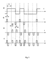
- Figure 3 illustrates the operation of the above-described character sequence forming.
- Fig. 3a shows the PNS sequence at the output of the code generator with a code period ⁇ t.
- Figure 3b shows a sequence of digital pulses from the narrow correlator output, i.e. after the adder 22.
- Figure 3 B demonstrates a sequence of gating correcting signals at the output of the delayed pulse generator.
- Fig.3 d demonstrates a combined signal, T. e. the signal from the narrow correlator output jointly with the gating signals for the multipath adjustment.
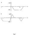
- Figure 4 illustrates the negative effect of the multipath phenomenon on the narrow correlator operation.
- Curve 1 in Fig. 4a represents an inverted output of the discriminator stipulated by the direct signal.
- Curve 2 is a response of the discriminator on delayed (multipath) signal, whose amplitude is equal to a half of the amplitude of the direct signal, and the delay makes a half of the duration of the character of the PNS code sequence. The delay between the early and late copies of the signal makes up 0.25 duration of the PNS character. For simplicity the calculation is made for the ideal case of a IF filter with an infinite passband.
- the discriminator output represents a summarized response to the direct and delayed signal (Fig. 4b, the signal is inverted). It is obvious that in this case the zero output of the discriminator corresponds to non-zero delay of the direct signal, i.e. the error in the range finding due to the multipath effect takes place.
- Figure 5a shows the result of correlation of the correcting signal with input PNS.
- the narrow correlator discriminator curve 1 in Fig. 4a
- the narrow correlator discriminator output with correcting gating signals shown in Fig. 5b (an inverted signal). It is clear that in this case the multipath signals with a delay longer than 1.5d do not render any effect on the discriminator signal.
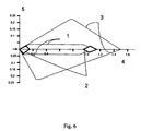
- Figure 6 presents a diagram of the distance errors of the discriminator of the C/A code signal depending on the delay of the multipath signal.
- E( ⁇ K ) [R f ( ⁇ K - d/2) - R f ( ⁇ K + d/2)] R f ( ⁇ K ) + ⁇ 2 [R f ( ⁇ K - d/2 - ⁇ ) - R f ( ⁇ K + d/2 - ⁇ ) R f ( ⁇ K - ⁇ ) + ⁇ [R f ( ⁇ K - d/2) - R f ( ⁇ K + d/2)]R f ( ⁇ K - ⁇ ) cos ⁇ m + ⁇ [R f ( ⁇ K - d/2 - ⁇ ) - R f ( ⁇ K + d/2 - ⁇ )] R f ( ⁇ K - ⁇ ) cos ⁇ m + ⁇ [R f ( ⁇ K - d/2 - ⁇ ) - R f ( ⁇ K + d/2 - ⁇ )] R f ( ⁇ K ) cos ⁇ m, ⁇ e R f( ⁇
- E( ⁇ K ) [R f ( ⁇ K - d/2) - R f ( ⁇ K + d/2)] R f ( ⁇ K ) + ⁇ 2 [R f ( ⁇ K - d/2 - ⁇ )- R f ( ⁇ K + d/2 - ⁇ ) R f ( ⁇ K - ⁇ ) + ⁇ [R f ( ⁇ K - d/2) - R f ( ⁇ K + d/2)]R f ( ⁇ K - ⁇ ) cos ⁇ m + ⁇ [R f ( ⁇ K - d/2 - ⁇ ) - R f ( ⁇ K + d/2 - ⁇ )] R f ( ⁇ K ) cos ⁇ m, + + S f ( ⁇ K + 1 + d/2) R f ( ⁇ K ) + ⁇ 2 S f ( ⁇
- Fig. 6 shows the results of the range finding errors for the ideal case of a filter with an infinite pass band.
Landscapes
- Engineering & Computer Science (AREA)
- Radar, Positioning & Navigation (AREA)
- Remote Sensing (AREA)
- Computer Networks & Wireless Communication (AREA)
- Physics & Mathematics (AREA)
- General Physics & Mathematics (AREA)
- Signal Processing (AREA)
- Position Fixing By Use Of Radio Waves (AREA)
- Digital Transmission Methods That Use Modulated Carrier Waves (AREA)
- Nitrogen And Oxygen Or Sulfur-Condensed Heterocyclic Ring Systems (AREA)
Applications Claiming Priority (1)
| Application Number | Priority Date | Filing Date | Title |
|---|---|---|---|
| PCT/RU1998/000286 WO2000016119A1 (fr) | 1998-09-15 | 1998-09-15 | Procede permettant d'accroitre l'insensibilite au brouillage lors de la reception de signaux provenant de systemes de navigation par satellite, et dispositif de mise en oeuvre de ce procede |
Publications (2)
| Publication Number | Publication Date |
|---|---|
| EP1031848A1 true EP1031848A1 (fr) | 2000-08-30 |
| EP1031848A4 EP1031848A4 (fr) | 2006-05-03 |
Family
ID=20130258
Family Applications (1)
| Application Number | Title | Priority Date | Filing Date |
|---|---|---|---|
| EP98962729A Withdrawn EP1031848A4 (fr) | 1998-09-15 | 1998-09-15 | Procede permettant d'accroitre l'insensibilite au brouillage lors de la reception de signaux provenant de systemes de navigation par satellite, et dispositif de mise en oeuvre de ce procede |
Country Status (7)
| Country | Link |
|---|---|
| US (1) | US7206336B1 (fr) |
| EP (1) | EP1031848A4 (fr) |
| JP (1) | JP3889566B2 (fr) |
| KR (1) | KR100547764B1 (fr) |
| CN (1) | CN1214252C (fr) |
| AU (1) | AU759574B2 (fr) |
| WO (1) | WO2000016119A1 (fr) |
Cited By (4)
| Publication number | Priority date | Publication date | Assignee | Title |
|---|---|---|---|---|
| EP1707980A1 (fr) * | 2005-03-31 | 2006-10-04 | Deere & Company | Procédé de configuration d'un système de positionnement local |
| DE102005028657A1 (de) * | 2005-06-20 | 2006-12-28 | Deutsches Zentrum für Luft- und Raumfahrt e.V. | Verfahren zum Reduzieren von durch Mehrwegeempfang verursachten Störungen in Satellitennavigationsempfängern und Navigations-empfänger zur Durchführung des Verfahrens |
| EP1616391A4 (fr) * | 2003-04-18 | 2007-06-20 | Motorola Inc | Procede et dispositif permettant de detecter un etat de brouillage |
| CN114930737A (zh) * | 2020-01-10 | 2022-08-19 | 华为技术有限公司 | 波束获取方法和通信设备 |
Families Citing this family (19)
| Publication number | Priority date | Publication date | Assignee | Title |
|---|---|---|---|---|
| KR100438396B1 (ko) * | 2001-11-06 | 2004-07-02 | 지규인 | 위성을 이용한 위치결정수신기의 실시간 다중경로오차검출방법 및 그 방법을 이용한 위치결정 장치 |
| CA2459428A1 (fr) * | 2004-03-03 | 2005-09-03 | Spotwave Wireless Inc. | Reconnaissance de signal dans un repeteur accorde |
| US7471717B2 (en) * | 2004-05-17 | 2008-12-30 | Yi Ping Huang | Apparatus and method for acquiring spread-spectrum signals |
| JP2006177783A (ja) * | 2004-12-22 | 2006-07-06 | Seiko Epson Corp | 測位装置、測位装置の制御方法、測位装置の制御プログラム、測位装置の制御プログラムを記録したコンピュータ読み取り可能な記録媒体 |
| FR2918765B1 (fr) * | 2007-07-09 | 2009-10-02 | Sagem Electronique Sa | Procede de determination d'une erreur d'asservissement dans une boucle de poursuite d'un code pseudo-aleatoire. |
| US8200446B2 (en) * | 2008-12-12 | 2012-06-12 | Qualcomm Incorporated | Waveform correlation result processing methods and apparatuses |
| US8660165B2 (en) * | 2009-06-11 | 2014-02-25 | Andrew Llc | System and method for detecting spread spectrum signals in a wireless environment |
| US8223821B2 (en) * | 2009-06-25 | 2012-07-17 | Andrew Llc | Uplink signal detection in RF repeaters |
| US8373593B2 (en) * | 2009-07-15 | 2013-02-12 | Topcon Gps, Llc | Navigation receiver for processing signals from a set of antenna units |
| CN102033219B (zh) * | 2009-09-29 | 2013-07-24 | 晨星软件研发(深圳)有限公司 | 用于定位系统的频率追踪方法及其装置 |
| US8115675B2 (en) * | 2010-02-05 | 2012-02-14 | Broadcom Corporation | Method and system for integrated GLONASS and GPS processing |
| CN102262231A (zh) * | 2010-05-31 | 2011-11-30 | 北京联星科通微电子技术有限公司 | Gps和glonass多信道并行信号编码混频方法及编码混合器 |
| KR101236115B1 (ko) * | 2010-05-31 | 2013-02-21 | 한국전자통신연구원 | 코드 추적 장치 및 방법 |
| RU2012104318A (ru) * | 2012-02-08 | 2013-08-20 | Корпорация "САМСУНГ ЭЛЕКТРОНИКС Ко., Лтд." | Способ и устройство навигации |
| CN110850446B (zh) * | 2019-07-16 | 2022-10-18 | 北京自动化控制设备研究所 | 一种卫星信号监测方法及系统 |
| CN112305516B (zh) * | 2019-07-31 | 2024-02-06 | 徐立 | 一种模数混合多波束形成及其在接收阵列中的应用 |
| CN112485332A (zh) * | 2020-11-16 | 2021-03-12 | 中国铁建重工集团股份有限公司 | 一种基于伪随机编码的无损检测系统及无损检测方法 |
| US12224891B2 (en) * | 2022-06-17 | 2025-02-11 | Mediatek Inc. | Method and apparatus for performing efficient correlation computation between data sequence and both of in-phase code sequence and quadrature code sequence |
| CN115542350A (zh) * | 2022-08-15 | 2022-12-30 | 芯与物(上海)技术有限公司 | 一种多径信号检测装置及方法 |
Family Cites Families (8)
| Publication number | Priority date | Publication date | Assignee | Title |
|---|---|---|---|---|
| US4807256A (en) * | 1985-12-23 | 1989-02-21 | Texas Instruments Incorporated | Global position system receiver |
| AU643272B2 (en) * | 1990-06-04 | 1993-11-11 | Raytheon Company | Global positioning system receiver |
| US5390207A (en) * | 1990-11-28 | 1995-02-14 | Novatel Communications Ltd. | Pseudorandom noise ranging receiver which compensates for multipath distortion by dynamically adjusting the time delay spacing between early and late correlators |
| DE69327119T2 (de) * | 1992-01-24 | 2000-06-21 | Novatel Inc., Calgary | Empfänger für pseudozufällige Rauschsignale, der Vielwegverzerrungen durch dynamisches Einstellen der Zeitverzögerung zwischen frühen und späten Korrelatoren kompensiert |
| WO1997006446A2 (fr) | 1995-08-09 | 1997-02-20 | Magellan Corporation | Reduction des erreurs par trajets multiples dans un recepteur a spectre etale pour mesures de distance |
| EP1586916B1 (fr) * | 1995-10-09 | 2011-06-01 | Snaptrack, Inc. | Récepteur GPS et procédé de traitement des signaux GPS |
| FR2742612B1 (fr) * | 1995-12-15 | 1998-02-06 | Sextant Avionique | Procede et circuit de reception de signaux de positionnement par satellites avec elimination des erreurs de multitrajets |
| US5903597A (en) * | 1996-05-20 | 1999-05-11 | Trimble Navigation Limited | Suppression on multipath signal effects |
-
1998
- 1998-09-15 EP EP98962729A patent/EP1031848A4/fr not_active Withdrawn
- 1998-09-15 JP JP2000570601A patent/JP3889566B2/ja not_active Expired - Fee Related
- 1998-09-15 US US09/554,392 patent/US7206336B1/en not_active Expired - Fee Related
- 1998-09-15 AU AU17900/99A patent/AU759574B2/en not_active Ceased
- 1998-09-15 CN CNB988128209A patent/CN1214252C/zh not_active Expired - Fee Related
- 1998-09-15 KR KR1020007005457A patent/KR100547764B1/ko not_active Expired - Fee Related
- 1998-09-15 WO PCT/RU1998/000286 patent/WO2000016119A1/fr not_active Ceased
Cited By (5)
| Publication number | Priority date | Publication date | Assignee | Title |
|---|---|---|---|---|
| EP1616391A4 (fr) * | 2003-04-18 | 2007-06-20 | Motorola Inc | Procede et dispositif permettant de detecter un etat de brouillage |
| EP1707980A1 (fr) * | 2005-03-31 | 2006-10-04 | Deere & Company | Procédé de configuration d'un système de positionnement local |
| DE102005028657A1 (de) * | 2005-06-20 | 2006-12-28 | Deutsches Zentrum für Luft- und Raumfahrt e.V. | Verfahren zum Reduzieren von durch Mehrwegeempfang verursachten Störungen in Satellitennavigationsempfängern und Navigations-empfänger zur Durchführung des Verfahrens |
| DE102005028657B4 (de) * | 2005-06-20 | 2007-02-08 | Deutsches Zentrum für Luft- und Raumfahrt e.V. | Verfahren zum Reduzieren von durch Mehrwegeempfang verursachten Störungen in Satellitennavigationsempfängern und Navigations-empfänger zur Durchführung des Verfahrens |
| CN114930737A (zh) * | 2020-01-10 | 2022-08-19 | 华为技术有限公司 | 波束获取方法和通信设备 |
Also Published As
| Publication number | Publication date |
|---|---|
| CN1214252C (zh) | 2005-08-10 |
| KR20010032254A (ko) | 2001-04-16 |
| KR100547764B1 (ko) | 2006-02-01 |
| EP1031848A4 (fr) | 2006-05-03 |
| WO2000016119A1 (fr) | 2000-03-23 |
| CN1285919A (zh) | 2001-02-28 |
| JP2002525891A (ja) | 2002-08-13 |
| JP3889566B2 (ja) | 2007-03-07 |
| AU759574B2 (en) | 2003-04-17 |
| US7206336B1 (en) | 2007-04-17 |
| AU1790099A (en) | 2000-04-03 |
Similar Documents
| Publication | Publication Date | Title |
|---|---|---|
| US7206336B1 (en) | Method of increasing noise immunity during reception of signals from satellite navigational systems | |
| JP4422337B2 (ja) | 高速・高感度gps受信器 | |
| JP3983812B2 (ja) | 改良された多経路信号除去作用を有する受信器 | |
| CN100399044C (zh) | 开环跟踪gps信号的方法 | |
| US6658048B1 (en) | Global positioning system code phase detector with multipath compensation and method for reducing multipath components associated with a received signal | |
| US7231095B2 (en) | Spread spectrum signal demodulation method and apparatus | |
| EP1052786A1 (fr) | Recepteur de signaux de pseudo-bruit provenant de systemes de radionavigation satellite | |
| EP3076204A1 (fr) | Corrélateur de balayage pour suivi d'un signal de système de navigation satellite mondial | |
| EP1322044A1 (fr) | Procede et dispositif de detection de la synchronisation d'un code d'etalement d'un signal a spectre etale | |
| JP2003533937A (ja) | コード位相トラッキング方法及び受信機 | |
| JPH09505404A (ja) | 多重相関器の時間遅延間隔を使用することにより多重経路歪みを補償する疑似ランダム雑音レンジング受信機 | |
| CN101030787B (zh) | 对扩频信号的信噪比提供估计的方法和装置 | |
| US6784830B1 (en) | Method for processing in dual frequency civilian GPS receiver | |
| KR100884705B1 (ko) | 통신 디바이스에서의 비트 동기화 | |
| JP4787349B2 (ja) | 整合フィルタ回路及びグローバルポジショニングシステム信号の獲得及び追跡方法 | |
| Meng | Low-power GPS receiver design | |
| JP2011047947A (ja) | 高速・高感度gps受信器 | |
| JP5118088B2 (ja) | グローバルポジショニングシステム信号を獲得及び追跡する方法及び装置 | |
| JP5587121B2 (ja) | 整合フィルタ回路及び整合フィルタリングを実行するための方法 | |
| US7839918B2 (en) | Method and device for estimating a frequency in the acquisition of a spread-spectrum code signal | |
| US20040240530A1 (en) | Multipath discriminator module for a navigation system | |
| Sadahalli | GPS L2C acquisition and tracking | |
| JPH112674A (ja) | Gps受信機 | |
| HK1071932B (en) | Method for open loop tracking gps signals | |
| AU8756098A (en) | Fast acquisition, high sensitivity gps receiver |
Legal Events
| Date | Code | Title | Description |
|---|---|---|---|
| PUAI | Public reference made under article 153(3) epc to a published international application that has entered the european phase |
Free format text: ORIGINAL CODE: 0009012 |
|
| 17P | Request for examination filed |
Effective date: 20000606 |
|
| AK | Designated contracting states |
Kind code of ref document: A1 Designated state(s): DE FR GB SE |
|
| 18D | Application deemed to be withdrawn |
Effective date: 20040331 |
|
| D18D | Application deemed to be withdrawn (deleted) | ||
| A4 | Supplementary search report drawn up and despatched |
Effective date: 20060317 |
|
| RIC1 | Information provided on ipc code assigned before grant |
Ipc: H04B 1/707 20060101ALI20060313BHEP Ipc: G01S 5/14 20060101AFI20000327BHEP |
|
| GRAP | Despatch of communication of intention to grant a patent |
Free format text: ORIGINAL CODE: EPIDOSNIGR1 |
|
| RTI1 | Title (correction) |
Free format text: METHOD AND DEVICE FOR INCREASING INTERFERENCE IMMUNITY WHEN RECEIVING SIGNALS FROM SATELLITE NAVIGATION SYSTEMS |
|
| GRAS | Grant fee paid |
Free format text: ORIGINAL CODE: EPIDOSNIGR3 |
|
| STAA | Information on the status of an ep patent application or granted ep patent |
Free format text: STATUS: THE APPLICATION IS DEEMED TO BE WITHDRAWN |
|
| R18D | Application deemed to be withdrawn (corrected) |
Effective date: 20090402 |