EP1031855A2 - Gierwinkelfühler für geschleppten Körper - Google Patents
Gierwinkelfühler für geschleppten Körper Download PDFInfo
- Publication number
- EP1031855A2 EP1031855A2 EP00102903A EP00102903A EP1031855A2 EP 1031855 A2 EP1031855 A2 EP 1031855A2 EP 00102903 A EP00102903 A EP 00102903A EP 00102903 A EP00102903 A EP 00102903A EP 1031855 A2 EP1031855 A2 EP 1031855A2
- Authority
- EP
- European Patent Office
- Prior art keywords
- towed
- fin
- central axis
- water
- arrangement
- Prior art date
- Legal status (The legal status is an assumption and is not a legal conclusion. Google has not performed a legal analysis and makes no representation as to the accuracy of the status listed.)
- Withdrawn
Links
Images

Classifications
-
- G—PHYSICS
- G01—MEASURING; TESTING
- G01V—GEOPHYSICS; GRAVITATIONAL MEASUREMENTS; DETECTING MASSES OR OBJECTS; TAGS
- G01V1/00—Seismology; Seismic or acoustic prospecting or detecting
- G01V1/38—Seismology; Seismic or acoustic prospecting or detecting specially adapted for water-covered areas
- G01V1/3817—Positioning of seismic devices
- G01V1/3826—Positioning of seismic devices dynamic steering, e.g. by paravanes or birds
-
- G—PHYSICS
- G01—MEASURING; TESTING
- G01V—GEOPHYSICS; GRAVITATIONAL MEASUREMENTS; DETECTING MASSES OR OBJECTS; TAGS
- G01V1/00—Seismology; Seismic or acoustic prospecting or detecting
- G01V1/16—Receiving elements for seismic signals; Arrangements or adaptations of receiving elements
- G01V1/20—Arrangements of receiving elements, e.g. geophone pattern
- G01V1/201—Constructional details of seismic cables, e.g. streamers
Definitions
- the present invention pertains to sonar sensors. More particularly, the invention relates to a system for sensing the direction of travel of a water borne; flexible, towed array of acoustic transducers or hydrophone sensors being drawn by a towed body which in turn is being pulled by a ship.
- Towed arrays of hydrophones are well known in the art. Such are long, continuous, neutrally buoyant hose lines, often several hundred meters long, which periodically contain numerous hydrophone receivers. Typically, these elongate arrays have a number of sensor elements in modules, along with their associated electronics and control leads, contained within a hose-shaped structure that extends through the water. The hydrophones are connected by suitable electronics on a towing vessel which indicates the bearing of an identified underwater target.
- Exemplary towed arrays are described in U.S. patents 4,554,650 and 5,412,621.
- sonar is either used passively, through reception of signals sent through water, or actively.
- an active sonar system a pulse of sound is sent into the water by a sonar projector. The sound is then reflected back from the target and detected by the hydrophone arrays as an echo. This echo is received as mechanical energy by an acoustic transducer, converted into electrical energy, and read by a computer on an attached vessel to pinpoint the location of objects within the water.
- elongated, hose-like towed arrays of hydrophones attached to the rear end of towed bodies are commonly used for the acoustic sensing of moving objects within the ocean.
- a problem with the typical towed array is that it must be properly aligned or the acoustic signals received may not indicate the true horizontal direction of underwater objects.
- To accurately locate the position of an underwater object it is necessary to know the direction of the towed arrays with respect to the direction of the towed body axis.
- the towed body tends to react to the movement of the ship as it is pulled through water, while the towed arrays line up with the varying water current flows.
- a yaw angle between the axis of a towed body and the direction of water current flow across the body will form during travel through water.
- These small heading sensors are expensive, difficult to integrate into the array and require elaborate and expensive facilities to perform calibration once installed. Such small heading sensors are about one inch in diameter and seven inches long.
- the sensor must be able to sense the magnetic field in any rotational orientation about its axis so the design has a 360 degree tilt sensor which is used to compensate the heading measurement as the array rolls relative to the horizontal.
- a more effective alternative method for sensing and correcting a yaw angle would be desired.
- a lower cost solution is to provide a single low cost, self calibrating heading sensor in the towed body along with the towed body yaw sensor.
- the towed body heading sensor measures the bearing of the towed body centerline which is ideally aligned with the water flow.
- the yaw angle sensor measures the angle of the towed body relative to the water flow direction.
- the present invention provides a towed body yaw angle sensor arrangement where a vessel draws a towed body and the towed body pulls a towed array.
- a submersible towed body is provided with a pivoting fin extending outwardly from a surface of the body, which fin aligns with the direction of flow of water along the fin.
- a magnetic compass is fixed to the body which calibrated to the central axis of the body and determines a heading of the central axis of the body. Suitable means determine an angle between the fin and the central axis. Since the fin and the towed array are free to align with the direction of water flow, the fin direction is indicative of the array direction. Thus the angle between the fin direction and the axis of the towed body indicates a correction angle between the array direction and the towed body heading. This angle corrects the bearing angle of a target as reported by the array.
- the invention provides a towed body yaw angle sensor arrangement which comprises:
- the invention also provides a method for sensing a towed body yaw angle which comprises:
- the invention further provides a method for correcting a towed body yaw angle which comprises:
- a towed body arrangement according to the invention.
- the arrangement comprises a submersible towed body 2 having a sensor fin 4 extending outwardly from a surface of the body.
- the towed body is submersible to a controllable depth and is deployed behind a towing vessel 6 via a towing cable or umbilical 8 that physically and electrically connects suitable electronics on the vessel 6 to the towed body 2.
- the fin 4 extends from either a top or bottom surface of the body 2 and is attached to and capable of pivoting about a point perpendicular to the surface of the body 2.
- the fin 4 is initially aligned with the central axis 10 of the towed body but aligns with the direction of flow of water along the fin 4 when the body 2 is towed through water.
- Towed body 2 draws one or more towed arrays of hydrophones 14 via a umbilical cable 12 which both draws the arrays and electrically connects the arrays to suitable electronics on the vessel 6.
- the towed arrays 14 comprises neutrally buoyant, flexible, hose walled devices which align with the flow of water.
- Such arrays 14 have long been used for the sensing of acoustic pressures and their configurations are many and varied to provide a desired sensing and frequency response.
- the towed body 2 has means for controlling its depth such as side fins 16 on alternate sides of the body.
- the arrangement preferably further comprises means for aligning the central axis of the body with the water flow when the body is towed through water, such as by one or more rudders 18.
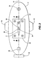
- Figure 2 shows a plan view of a sensor on a towed body arrangement. It shows fin 4 on a mounting plate 20 which is attached to the top surface of towed body 2 perpendicular to a horizontal plane through the central axis of the body. Alternatively the fin may extend from a bottom surface of the body perpendicular to a horizontal plane through the central axis of the body. Fin 4 is pivotable about a mounting dowel 22.
- the sensor is aligned to center axis 10 of the towed body 2 using a high precision mounting dowel pin 22 press fit into the towed body structure. The pin fits into the sensor base to align its center axis with the axis of the towed body to within +/- 0.1 degrees.
- the degree of pivot of the fin 4 about the dowel 22 is limited by a stop 24 attached to the body 2 and located within a slot 26 which extends through fin 4.
- a bearing reference for the towed body is a magnetic compass 34 fixed to the towed body 2 as shown in Figure 2.
- the compass 34 is aligned with the central axis of the body 2 for determining a heading of the central axis 10 of the body 2 when the body is towed through water.
- the compass is aligned to within ⁇ .1° of the central axis of the body.
- the inventive arrangement also comprises means for determining an angle between the fin and a central axis of the submersible body.
- the degree of pivot of fin 4 is sensed by Hall effect sensor 28 which is activated by a magnet 30 on the fin. Sensing information is relayed to the electronics on the towing vessel via cable 8.
- the angle between the fin and a central axis of the submersible body is a difference calculation between the position of the fin as indicated by the sensor and the bearing of the central axis as determined by the compass. This may be done by a computer which continually receives such bearing and positioning information via umbilical cable 8.
- a sonar projector 36 is incorporated as part of the inventive arrangement.
- the sonar projector 36 may be incorporated within the body 2.
- the projector 36 may be located on the body 2, deployed either with or behind the body 2, or may be on the towing vessel 6.
- the projector 36 sends out acoustic waves that reflect off a target in the sea, and return echoes are received by towed arrays 14. Once the reflected acoustic signals are received by arrays 14 they are converted into electrical signals and transmitted to a computer on the towing vessel 6.
- a continuous signal is sent via cable 8 to a computer on tow vessel 6 records the position of the central axis 10.
- a magnet 30 on fin 4 along with a Hall effect magnetic field sensor 28 on or in the body 2 senses the angle of the fin due to the flow of water and thus measures the direction of the towed arrays 14.
- the yaw angle data is continuously transmitted back to the towing vessel 6 via the towing cable 8 where it is received by a computer that calculates an angular difference between the heading of the central axis 10 of the body 2 and the angle of the fin 4.
- the yaw angle of the towed body my be eliminated by steering one or more rudders 18 on the body 2 to align the central body axis 10 with the water flow. Alignment correction of the towed body with the water flow also reduces sonar processing errors due to non-uniform array sensor geometry created by skewed array tow points when the towed body is yawed.
- the sensor may be calibrated by taking readings of the signal sent to a computer on the vessel 6 via cable 8 with the sensor fin aligned to +5°, -5°, and 0° tick marks on the top of the sensor base.
- the calibration of the sensor is easily maintained by periodically repeating these sensor readings with the fin aligned to the tick marks.
- the invention also provides a method for sensing a towed body yaw angle.
- First the towed body yaw angle sensor arrangement is provided.
- the next steps are to determine the heading of the central axis of the body using compass 18 and the angle between the fin 4 and central axis 10 of the towed body 2 using sensor 28. Once these values are known, an angular difference between the heading of the central axis 10 and the fin 4 can be calculated. This is the towed body yaw angle.
- the invention further provides a method for correcting a towed body yaw angle. This includes each of the steps above with the further step of aligning the central axis of the body with the water flow using one or more rudders on the towed body 2.
Landscapes
- Life Sciences & Earth Sciences (AREA)
- Physics & Mathematics (AREA)
- Engineering & Computer Science (AREA)
- Acoustics & Sound (AREA)
- Environmental & Geological Engineering (AREA)
- Geology (AREA)
- Remote Sensing (AREA)
- General Life Sciences & Earth Sciences (AREA)
- General Physics & Mathematics (AREA)
- Geophysics (AREA)
- Oceanography (AREA)
- Measurement Of Velocity Or Position Using Acoustic Or Ultrasonic Waves (AREA)
Applications Claiming Priority (2)
| Application Number | Priority Date | Filing Date | Title |
|---|---|---|---|
| US09/256,444 US6111817A (en) | 1999-02-23 | 1999-02-23 | Towed body yaw angle sensor |
| US256444 | 2002-09-26 |
Publications (2)
| Publication Number | Publication Date |
|---|---|
| EP1031855A2 true EP1031855A2 (de) | 2000-08-30 |
| EP1031855A3 EP1031855A3 (de) | 2004-04-28 |
Family
ID=22972260
Family Applications (1)
| Application Number | Title | Priority Date | Filing Date |
|---|---|---|---|
| EP00102903A Withdrawn EP1031855A3 (de) | 1999-02-23 | 2000-02-12 | Gierwinkelfühler für geschleppten Körper |
Country Status (3)
| Country | Link |
|---|---|
| US (1) | US6111817A (de) |
| EP (1) | EP1031855A3 (de) |
| CA (1) | CA2298389A1 (de) |
Cited By (4)
| Publication number | Priority date | Publication date | Assignee | Title |
|---|---|---|---|---|
| FR2820826A1 (fr) * | 2001-02-15 | 2002-08-16 | Cgg Marine | Procede de determination du courant marin et dispositif associe |
| DE10122269A1 (de) * | 2001-05-08 | 2002-11-21 | Degussa | Silanmodifizierter biopolymerer, biooligomerer, oxidischer oder silikatischer Füllstoff, Verfahren zu seiner Herstellung und seine Verwendung |
| EP2857869A1 (de) * | 2013-10-07 | 2015-04-08 | Sercel | Betriebsverwaltungssystem zur Ansteuerung einer Navigationssteuerungsvorrichtung entsprechend eines herabgestuften Betriebsmodus |
| WO2017059423A1 (en) * | 2015-10-02 | 2017-04-06 | Woods Hole Oceanographic Institution | Articulating moored profiler system |
Families Citing this family (13)
| Publication number | Priority date | Publication date | Assignee | Title |
|---|---|---|---|---|
| US7252046B1 (en) | 2003-12-08 | 2007-08-07 | The United States Of America As Represented By The Secretary Of The Navy | Apparatus for deploying and recovering a towed acoustic line array from an unmanned undersea vehicle |
| US7457193B2 (en) * | 2006-07-21 | 2008-11-25 | Pgs Geophysical As | Seismic source and source array having depth-control and steering capability |
| US7782712B2 (en) * | 2008-06-05 | 2010-08-24 | The United States Of America As Represented By The Secretary Of The Navy | Device for estimating local towed array angles |
| FR2940838B1 (fr) * | 2009-01-05 | 2012-12-28 | Michel Manin | Procede et dispositif ameliores de prospection sismique marine |
| US9535182B2 (en) * | 2009-03-09 | 2017-01-03 | Ion Geophysical Corporation | Marine seismic surveying with towed components below water surface |
| CN101706574B (zh) * | 2009-10-30 | 2013-03-13 | 中国科学院声学研究所 | 一种双鳍阵声纳设备 |
| CN101702028B (zh) * | 2009-10-30 | 2011-11-09 | 中国科学院声学研究所 | 一种单鳍阵声纳设备 |
| US8570829B2 (en) * | 2009-12-22 | 2013-10-29 | Pgs Geophysical As | Depth steerable seismic source array |
| US9057738B1 (en) * | 2012-11-02 | 2015-06-16 | The United States Of America As Represented By The Secretary Of The Navy | Inertial dynamics measurement and structural configuration variation for hydrodynamic stability evaluation of a towed body |
| FR3033157B1 (fr) * | 2015-02-27 | 2018-03-23 | Thales | Poisson a portance hydrodynamique variable et ligne de remorquage comprenant le poisson |
| FR3054890B1 (fr) | 2016-08-02 | 2019-07-05 | Kietta | Controle de la position horizontale d’un cable sismique |
| US11041720B2 (en) * | 2016-12-13 | 2021-06-22 | Pgs Geophysical As | Calibration of a magnetometer in a towed object telemetry unit based on turn data |
| US12292537B2 (en) * | 2022-07-11 | 2025-05-06 | Sercel | Seismic equipment connecting module and method |
Family Cites Families (8)
| Publication number | Priority date | Publication date | Assignee | Title |
|---|---|---|---|---|
| US4992999A (en) * | 1966-07-28 | 1991-02-12 | The United States Of America As Represented By The Secretary Of The Navy | Submarine drone for carrying a barrel stave-type transducer array |
| US3774570A (en) * | 1972-01-25 | 1973-11-27 | Whitehall Electronics Corp | Non-rotating depth controller paravane for seismic cables |
| US4068208A (en) * | 1975-07-14 | 1978-01-10 | Texas Instruments Incorporated | Marine streamer position determination system |
| US4554650A (en) * | 1982-04-02 | 1985-11-19 | The United States Of America As Represented By The Secretary Of The Navy | Oil filled towed array hose without couplings |
| US5844860A (en) * | 1990-05-23 | 1998-12-01 | The United States Of America As Represented By The Secretary Of The Navy | Continuous strength member |
| US5412621A (en) * | 1993-09-23 | 1995-05-02 | Whitehall Corporation | Encapsulated hydrophone element for towed hydrophone array |
| CA2232562C (en) * | 1995-09-22 | 2008-07-29 | The Laitram Corporation | Electrical power distribution and communication system for an underwater cable |
| AU740881B2 (en) * | 1997-06-12 | 2001-11-15 | Ion Geophysical Corporation | Depth control device for an underwater cable |
-
1999
- 1999-02-23 US US09/256,444 patent/US6111817A/en not_active Expired - Fee Related
-
2000
- 2000-02-12 EP EP00102903A patent/EP1031855A3/de not_active Withdrawn
- 2000-02-14 CA CA002298389A patent/CA2298389A1/en not_active Abandoned
Cited By (8)
| Publication number | Priority date | Publication date | Assignee | Title |
|---|---|---|---|---|
| FR2820826A1 (fr) * | 2001-02-15 | 2002-08-16 | Cgg Marine | Procede de determination du courant marin et dispositif associe |
| WO2002065156A1 (fr) * | 2001-02-15 | 2002-08-22 | Cgg Marine | Procede de determination du courant marin et dispositif associe |
| US7161871B2 (en) | 2001-02-15 | 2007-01-09 | Cgg Marine | Method for determining ocean current and associated device |
| DE10122269A1 (de) * | 2001-05-08 | 2002-11-21 | Degussa | Silanmodifizierter biopolymerer, biooligomerer, oxidischer oder silikatischer Füllstoff, Verfahren zu seiner Herstellung und seine Verwendung |
| EP2857869A1 (de) * | 2013-10-07 | 2015-04-08 | Sercel | Betriebsverwaltungssystem zur Ansteuerung einer Navigationssteuerungsvorrichtung entsprechend eines herabgestuften Betriebsmodus |
| US9599736B2 (en) | 2013-10-07 | 2017-03-21 | Sercel | Operation managing system for driving a navigation control device according to a degraded operating mode |
| WO2017059423A1 (en) * | 2015-10-02 | 2017-04-06 | Woods Hole Oceanographic Institution | Articulating moored profiler system |
| US10611437B2 (en) | 2015-10-02 | 2020-04-07 | Woods Hole Oceanographic Institution | Articulating moored profiler system |
Also Published As
| Publication number | Publication date |
|---|---|
| CA2298389A1 (en) | 2000-08-23 |
| US6111817A (en) | 2000-08-29 |
| EP1031855A3 (de) | 2004-04-28 |
Similar Documents
| Publication | Publication Date | Title |
|---|---|---|
| US6111817A (en) | Towed body yaw angle sensor | |
| US6501704B2 (en) | Underwater object positioning system | |
| US9223002B2 (en) | System and method for determining the position of an underwater vehicle | |
| US6681710B2 (en) | System for controlling a marine seismic array | |
| US6208584B1 (en) | Place calibration of sonar receive array | |
| US12345846B2 (en) | Detecting objects submerged in a body of water or at least partly buried in a bed of the body of water | |
| CA1195762A (en) | Submerged marine streamer locator | |
| KR100831646B1 (ko) | 4개의 1/4 환형원판 배열 음향 트랜스듀서와 수중 카메라를이용한 무인잠수정의 수중 도킹 유도 장치 | |
| JPS60500383A (ja) | 海洋地震探査用水中聴音器ケ−ブルにおける装置 | |
| JPS61181983A (ja) | 水中の音波の受信装置 | |
| US20160195626A1 (en) | Method and System for Determining the Position of Control Devices on a Seismic Instrumented Towed Cable | |
| CN112147578B (zh) | 一种高精度深水发射阵及多元垂直接收阵阵元定位系统与方法 | |
| US11953321B2 (en) | Method for establishing a consolidated water current velocity profile | |
| KR102123232B1 (ko) | 소형 소나를 이용한 수심 측정장치 | |
| TWI696840B (zh) | 水下聲納量測校正裝置與方法 | |
| JP2006220436A (ja) | マルチビーム音響測深装置の動揺影響軽減装置又はこれを備えた海底探査船 | |
| JP2755863B2 (ja) | 水中航走体の位置検出装置及びその位置検出方法 | |
| JP2001116829A (ja) | 水中音響試験装置の位置・方位保持方法 | |
| AU2012200886A1 (en) | System and method for determining the position of an underwater vehicle | |
| CN114018224A (zh) | 一种海图水深数据检核系统和方法 | |
| RU2271021C1 (ru) | Способ определения трассы и глубины прокладки подводного кабеля | |
| KR102776814B1 (ko) | 수심측량 장비의 수평유지장치 | |
| EP3912899B1 (de) | Vorrichtung zur unterstützung einer seabed-messung unterwassersystem | |
| CN216013634U (zh) | 一种水面活动平台用的水声接收器位置实时自校准装置 | |
| KR102939243B1 (ko) | 수색용 드론 조립체 |
Legal Events
| Date | Code | Title | Description |
|---|---|---|---|
| PUAI | Public reference made under article 153(3) epc to a published international application that has entered the european phase |
Free format text: ORIGINAL CODE: 0009012 |
|
| AK | Designated contracting states |
Kind code of ref document: A2 Designated state(s): AT BE CH CY DE DK ES FI FR GB GR IE IT LI LU MC NL PT SE |
|
| AX | Request for extension of the european patent |
Free format text: AL;LT;LV;MK;RO;SI |
|
| PUAL | Search report despatched |
Free format text: ORIGINAL CODE: 0009013 |
|
| AK | Designated contracting states |
Kind code of ref document: A3 Designated state(s): AT BE CH CY DE DK ES FI FR GB GR IE IT LI LU MC NL PT SE |
|
| AX | Request for extension of the european patent |
Extension state: AL LT LV MK RO SI |
|
| 17P | Request for examination filed |
Effective date: 20040513 |
|
| AKX | Designation fees paid |
Designated state(s): DE FR GB IT |
|
| STAA | Information on the status of an ep patent application or granted ep patent |
Free format text: STATUS: THE APPLICATION IS DEEMED TO BE WITHDRAWN |
|
| 18D | Application deemed to be withdrawn |
Effective date: 20060901 |