EP1031952A2 - Système de surveillance - Google Patents
Système de surveillance Download PDFInfo
- Publication number
- EP1031952A2 EP1031952A2 EP00103608A EP00103608A EP1031952A2 EP 1031952 A2 EP1031952 A2 EP 1031952A2 EP 00103608 A EP00103608 A EP 00103608A EP 00103608 A EP00103608 A EP 00103608A EP 1031952 A2 EP1031952 A2 EP 1031952A2
- Authority
- EP
- European Patent Office
- Prior art keywords
- monitoring system
- track
- unit
- monitoring
- pulley
- Prior art date
- Legal status (The legal status is an assumption and is not a legal conclusion. Google has not performed a legal analysis and makes no representation as to the accuracy of the status listed.)
- Granted
Links
Images


Classifications
-
- G—PHYSICS
- G08—SIGNALLING
- G08B—SIGNALLING SYSTEMS, e.g. PERSONAL CALLING SYSTEMS; ORDER TELEGRAPHS; ALARM SYSTEMS
- G08B13/00—Burglar, theft or intruder alarms
- G08B13/18—Actuation by interference with heat, light, or radiation of shorter wavelength; Actuation by intruding sources of heat, light, or radiation of shorter wavelength
- G08B13/189—Actuation by interference with heat, light, or radiation of shorter wavelength; Actuation by intruding sources of heat, light, or radiation of shorter wavelength using passive radiation detection systems
- G08B13/194—Actuation by interference with heat, light, or radiation of shorter wavelength; Actuation by intruding sources of heat, light, or radiation of shorter wavelength using passive radiation detection systems using image scanning and comparing systems
- G08B13/196—Actuation by interference with heat, light, or radiation of shorter wavelength; Actuation by intruding sources of heat, light, or radiation of shorter wavelength using passive radiation detection systems using image scanning and comparing systems using television cameras
- G08B13/19634—Electrical details of the system, e.g. component blocks for carrying out specific functions
-
- F—MECHANICAL ENGINEERING; LIGHTING; HEATING; WEAPONS; BLASTING
- F16—ENGINEERING ELEMENTS AND UNITS; GENERAL MEASURES FOR PRODUCING AND MAINTAINING EFFECTIVE FUNCTIONING OF MACHINES OR INSTALLATIONS; THERMAL INSULATION IN GENERAL
- F16M—FRAMES, CASINGS OR BEDS OF ENGINES, MACHINES OR APPARATUS, NOT SPECIFIC TO ENGINES, MACHINES OR APPARATUS PROVIDED FOR ELSEWHERE; STANDS; SUPPORTS
- F16M11/00—Stands or trestles as supports for apparatus or articles placed thereon ; Stands for scientific apparatus such as gravitational force meters
- F16M11/02—Heads
- F16M11/18—Heads with mechanism for moving the apparatus relatively to the stand
-
- F—MECHANICAL ENGINEERING; LIGHTING; HEATING; WEAPONS; BLASTING
- F16—ENGINEERING ELEMENTS AND UNITS; GENERAL MEASURES FOR PRODUCING AND MAINTAINING EFFECTIVE FUNCTIONING OF MACHINES OR INSTALLATIONS; THERMAL INSULATION IN GENERAL
- F16M—FRAMES, CASINGS OR BEDS OF ENGINES, MACHINES OR APPARATUS, NOT SPECIFIC TO ENGINES, MACHINES OR APPARATUS PROVIDED FOR ELSEWHERE; STANDS; SUPPORTS
- F16M11/00—Stands or trestles as supports for apparatus or articles placed thereon ; Stands for scientific apparatus such as gravitational force meters
- F16M11/42—Stands or trestles as supports for apparatus or articles placed thereon ; Stands for scientific apparatus such as gravitational force meters with arrangement for propelling the support stands on wheels
- F16M11/425—Stands or trestles as supports for apparatus or articles placed thereon ; Stands for scientific apparatus such as gravitational force meters with arrangement for propelling the support stands on wheels along guiding means
-
- G—PHYSICS
- G08—SIGNALLING
- G08B—SIGNALLING SYSTEMS, e.g. PERSONAL CALLING SYSTEMS; ORDER TELEGRAPHS; ALARM SYSTEMS
- G08B13/00—Burglar, theft or intruder alarms
- G08B13/18—Actuation by interference with heat, light, or radiation of shorter wavelength; Actuation by intruding sources of heat, light, or radiation of shorter wavelength
- G08B13/189—Actuation by interference with heat, light, or radiation of shorter wavelength; Actuation by intruding sources of heat, light, or radiation of shorter wavelength using passive radiation detection systems
- G08B13/194—Actuation by interference with heat, light, or radiation of shorter wavelength; Actuation by intruding sources of heat, light, or radiation of shorter wavelength using passive radiation detection systems using image scanning and comparing systems
- G08B13/196—Actuation by interference with heat, light, or radiation of shorter wavelength; Actuation by intruding sources of heat, light, or radiation of shorter wavelength using passive radiation detection systems using image scanning and comparing systems using television cameras
- G08B13/19617—Surveillance camera constructional details
- G08B13/19623—Arrangements allowing camera linear motion, e.g. camera moving along a rail cable or track
Definitions
- the invention relates to a monitoring system as is usually used to monitor publicly accessible premises, such as shops and in particular large-scale sales outlets can be used.
- Such systems are generally intended to perform two tasks, namely both one - mostly optically implemented - monitoring of the premises and the goods displayed therein, as well as a certain deterrent effect to potential thieves. Both require commitment a relatively high number of monitoring units in where the cameras, video recorders etc. are located, per square meter of the area to be monitored. Out Cost reasons and the convenience of monitoring for the sake of it, but is also sought in large restaurants use as few monitoring units as possible.
- Around Using these well can sometimes be fixed monitoring units used either multiple cameras included or designed to be vertical and can rotate around a horizontal axis. But even then it remains from a single monitoring unit monitored area quite limited, what large areas the use of numerous monitoring units demands.
- the present invention enables both of the above tasks with the lowest possible Number of monitoring units to be met. To this Purpose is as defined in claim 1 defined.
- the invention allows one or a few monitoring units a deterrent to exercise which is that of a larger number even from conventional, fixed monitoring units surpasses. Because even the apparently targeted Movement of a monitoring unit over the head of a potential thief, or along one he has treaded Path between goods displays, looks more worrying than the silent presence of fixed surveillance units, assess the perspective of the potential thief can or believes to be able to.
- a surveillance system of those considered here Art usually includes a central control unit and at least one, usually above head height in the area to be monitored Room mounted, monitoring unit in the example a video camera controlled by the control unit, Loudspeakers for the transmission of messages and occasional warnings and other aids are. All these components are known to the person skilled in the art, it will therefore only be shown here how Monitoring unit of a system according to the invention in attached to a premises to be monitored or moved can be.
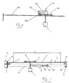
- FIG. 1 shows schematically an embodiment the system according to the invention.
- the reference number 1 denotes the housing of the monitoring unit, in the following abbreviated to satellite.
- the satellite 1 is from one lengthwise slotted or multi-part hollow beam 5 worn, of which Figure 1 for clarity only the (thick drawn) top surface 2 shows. On this rolls a trolley 3 provided with rollers 4 on the satellite 1 is suspended.
- the carriage 3 is moved by means of pulling ropes, whereby always a pair of symmetrical for each function vertical central axis of the beam arranged cables is provided to tilt the carriage 3 or one pulley unit (or Bogie) described below 15 to avoid.
- This symmetry is from the figure 2b can be seen while FIG. 1 and its description for the sake of simplicity, only one of the two running side by side Traction ropes shows or describes.
- in the Inside of the hollow beam 5 is one on the opposite End of the beam attached pull rope 6, 8 housed. This can consist of a single piece, but for the sake of clarity, it’s two sections, a passive section 6 and an active section Section 8, consisting of described.
- the passive section 6 ranges from a first one (to the left in the figure) Anchor point 7 to a pulley 10, which on a freely movable in the longitudinal direction of the bar Bogie 15 is attached, in Fig. 1 only by one thick line is indicated, and from there back to an attachment point 9 on the carriage 3.
- the active section 8 extends from this point over an am first deflection roller 11 located on the left end of the bar to one at the opposite end, second deflection roller 12, then from there to the pulley 10, and back again to one (in the figure right)) freely rotating compensating roller 18 with vertical axis.
- a second runs from there Back of the pull rope in a symmetrical manner, and indeed along a path of vertical Longitudinal axis of the bar mirror-symmetrical to the first, from Anchor point 7 extending to the compensating roller 18 first dreams.
- One from a circuit only indicated 17 controlled motor 16 drives the drive roller acting first pulley 11. As can be seen from FIG. 1, can thereby the carriage 3 and thus the satellite 1 can be moved over a distance L, which is only around is a little shorter than bar 5.
- the current position of the car 3 lengthways the beam 5 is by an optical mounted on the carriage Monitored the facility in a known manner Reads a series of marks on the bar. Around the corresponding signals, as well as others from the satellite signals originating or directed to it, and to supply him with the necessary electricity electrical lines are provided which extend from the carriage 3 extend to the vicinity of the left anchor point 7, and essentially along a path parallel to that of the passive part 6 of the pull rope. Accordingly, only part 6 'of this is in FIG. 1 Lines visible from one attached to Bogie 15 Reversing roller extends to carriage 3.
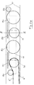
- FIG. 2a shows schematically the Bogie 15, which including the pulley 10 carries.
- the bogie consists essentially of a dotted line and designated 15, which is a series of freely movable supporting, deflecting and Carries leadership roles.
- the body rolls in a load-bearing manner Cover 21 with a rectangular cross section of the beam 5, from only the top and bottom surfaces are shown in FIG. 2a are.
- the bogie points out the following Roles and pairs of roles, the pairs always two, with respect to the vertical longitudinal axis of the beam there are mirror-symmetrical rollers or wheels.
- a pair of pinch rollers 50 for the one leading to the carriage Harness 6 '.
- a pair of guide drums 26 for the electrical lines 6 ', 6' '.
- One free to one vertical Axis rotatable guide roller 51 which guides the bogie by being on the inside surface of one side or the other of the hollow beam rolls.
- the support and guide rollers 51 to 54 preferably made of polyurethane.
- Figure 2b shows a schematic Section along II-II of Figure 2a.
- the bar consists of a torsion-resistant hollow profile 20 with a rectangular cross-section and a supporting shell 21, for example curved sheet.
- the bar can be made in the longitudinal direction be composed of several profiles and a total length of over 20 m.
- Hanger provided to the beam for example on the ceiling of a hall to be monitored hang up.
- the body 15 of the bogie is again only indicated by dotted lines.
- the symmetrical to vertical central plane of the bar, arranged in figure 2a pair of pulley pulleys, generally designated 10 has two outer deflection disks 24 for the passive Section 6 of the pull rope and two internal ones Deflection disks 25 for its active section 8.
- the outer disks 24 run on ball bearings 31 on a axis 28 attached to the body 15.
- Fig. 2b contains another Section through the guide roller 53, the vertical axis however lies outside of this section (see FIG. 2a), in order not to cross the axis 28 of the deflection disks.
- FIG. 3 schematically shows another Embodiment of the invention in which the monitoring unit Carriages do not run alongside pull cables an essentially straight path but is a rail vehicle that is self-sufficient on one, sometimes with curves and switches, Rail network moves.
- the vehicle either its own energy source, such as one carry a rechargeable battery and / or have to Busbars can be provided along its entire path.
- radio-controlled design 1 again the satellite with the monitoring unit, 35 a generally flat rail network May have curves and switches, and 36 one on it moving rail vehicle. At least one driving wheel 37 of this vehicle is driven by an electric motor 38.
- This can be indicated by a (not shown) the rechargeable battery carried on the rail vehicle or fed by busbars.
- the charging the battery can, for example, on a along the Rail path arranged charging station performed to which the vehicle automatically turns when needed connects.
- a control circuit 39 receives the necessary ones Commands either wirelessly (e.g. by radio over a Antenna 40), or via connections that are in certain places the train are intended for stationary operation.
- the control circuit takes care of the control of all necessary Operations in a manner known to those skilled in the art which is therefore not further discussed here.
- Figure 4 shows a suitable for large halls Execution of the suspension of the web along which the Monitoring unit can be moved.
- the figure is a view in the longitudinal direction of the web on one of several suspensions formed by ropes along the Track are arranged. This is shown in FIG. 2b in FIG. 20 Hollow profile indicated, which carries the web.
- On continuous suspension cable 41 runs from an upper corner A of the hollow profile 20 to a point D on the ceiling 42 of the Room, from there to the other upper corner B of the hollow profile, then back to A and on to a second point C on the ceiling 42 of the room, and finally from there to B.
Landscapes
- Engineering & Computer Science (AREA)
- General Engineering & Computer Science (AREA)
- Physics & Mathematics (AREA)
- General Physics & Mathematics (AREA)
- Mechanical Engineering (AREA)
- Train Traffic Observation, Control, And Security (AREA)
- Closed-Circuit Television Systems (AREA)
- Distillation Of Fermentation Liquor, Processing Of Alcohols, Vinegar And Beer (AREA)
- Jellies, Jams, And Syrups (AREA)
- Alcoholic Beverages (AREA)
- Control Of Position, Course, Altitude, Or Attitude Of Moving Bodies (AREA)
- Iron Core Of Rotating Electric Machines (AREA)
- Electric Cable Installation (AREA)
Applications Claiming Priority (2)
| Application Number | Priority Date | Filing Date | Title |
|---|---|---|---|
| DE29903350U DE29903350U1 (de) | 1999-02-24 | 1999-02-24 | Überwachungsanlage |
| DE29903350U | 1999-02-24 |
Publications (3)
| Publication Number | Publication Date |
|---|---|
| EP1031952A2 true EP1031952A2 (fr) | 2000-08-30 |
| EP1031952A3 EP1031952A3 (fr) | 2001-08-22 |
| EP1031952B1 EP1031952B1 (fr) | 2003-04-02 |
Family
ID=8069908
Family Applications (1)
| Application Number | Title | Priority Date | Filing Date |
|---|---|---|---|
| EP00103608A Expired - Lifetime EP1031952B1 (fr) | 1999-02-24 | 2000-02-21 | Système de surveillance |
Country Status (4)
| Country | Link |
|---|---|
| US (1) | US6614468B1 (fr) |
| EP (1) | EP1031952B1 (fr) |
| AT (1) | ATE236441T1 (fr) |
| DE (2) | DE29903350U1 (fr) |
Cited By (1)
| Publication number | Priority date | Publication date | Assignee | Title |
|---|---|---|---|---|
| EP1494480A1 (fr) * | 2003-07-04 | 2005-01-05 | Hymatom | Système de vidéosurveillance à caméra mobile |
Families Citing this family (12)
| Publication number | Priority date | Publication date | Assignee | Title |
|---|---|---|---|---|
| AUPQ017199A0 (en) * | 1999-05-06 | 1999-05-27 | Lextar Technologies Limited | A system for surveillance of an area |
| DE10007021A1 (de) * | 2000-02-16 | 2001-08-30 | Joachim Seidel | Überwachungseinrichtung mit einer Kamera |
| IL150123A0 (en) * | 2002-06-10 | 2003-07-06 | Shahar Avneri | Security system |
| US7189909B2 (en) | 2004-11-23 | 2007-03-13 | Román Viñoly | Camera assembly for finger board instruments |
| US7703996B1 (en) * | 2006-03-13 | 2010-04-27 | Sti, Inc. | Surveillance unit and method of use thereof |
| US10049542B2 (en) | 2012-11-04 | 2018-08-14 | Magal Security Systems Ltd. | Self-propelled security system on an adjacent to a fence track |
| WO2014068570A1 (fr) * | 2012-11-04 | 2014-05-08 | Magal Security Systems Ltd. | Système de sécurité autopropulsé sur une voie voisine d'une clôture |
| US9269242B2 (en) * | 2013-04-05 | 2016-02-23 | Peter Lust, Jr. | ASVVMS=Autonomous Space Vehicle Video Monitoring System |
| CN107945386A (zh) * | 2018-01-07 | 2018-04-20 | 李宝华 | 智能零售的无人售卖机 |
| CN108468924B (zh) * | 2018-03-28 | 2019-11-29 | 湖北海洋工程装备研究院有限公司 | 一种升降滑移装置 |
| CN112213515A (zh) * | 2020-09-18 | 2021-01-12 | 中煤科工集团重庆研究院有限公司 | 3u型巷道断面平均风速监测装置和方法 |
| CN113487839B (zh) * | 2021-09-08 | 2021-11-19 | 西南交通大学 | 一种便于安装的自然灾害预警用预警装置及其使用方法 |
Family Cites Families (6)
| Publication number | Priority date | Publication date | Assignee | Title |
|---|---|---|---|---|
| US4510526A (en) * | 1983-04-19 | 1985-04-09 | Coutta John M | Surveillance system |
| DE3825097A1 (de) * | 1988-07-23 | 1990-02-08 | Stahl R Foerdertech Gmbh | Vorrichtung zur positionsmessung bei kran- und elektrohaengebahnen |
| US5241380A (en) * | 1991-05-31 | 1993-08-31 | Video Sentry Corporation | Track mounted surveillance system having multiple use conductors |
| US5225863A (en) * | 1991-08-15 | 1993-07-06 | Weir Jones Iain | Remotely operated camera system with battery recharging system |
| FR2698739B1 (fr) * | 1992-11-30 | 1995-02-17 | Dessins Tech Ingenierie | Dispositif de tension pour les câbles d'alimentation et coaxial d'une caméra déplacée dans un tunnel de surveillance vidéo. |
| US5526041A (en) * | 1994-09-07 | 1996-06-11 | Sensormatic Electronics Corporation | Rail-based closed circuit T.V. surveillance system with automatic target acquisition |
-
1999
- 1999-02-24 DE DE29903350U patent/DE29903350U1/de not_active Expired - Lifetime
-
2000
- 2000-02-18 US US09/507,375 patent/US6614468B1/en not_active Expired - Fee Related
- 2000-02-21 AT AT00103608T patent/ATE236441T1/de not_active IP Right Cessation
- 2000-02-21 EP EP00103608A patent/EP1031952B1/fr not_active Expired - Lifetime
- 2000-02-21 DE DE50001588T patent/DE50001588D1/de not_active Expired - Fee Related
Cited By (2)
| Publication number | Priority date | Publication date | Assignee | Title |
|---|---|---|---|---|
| EP1494480A1 (fr) * | 2003-07-04 | 2005-01-05 | Hymatom | Système de vidéosurveillance à caméra mobile |
| FR2857202A1 (fr) * | 2003-07-04 | 2005-01-07 | Hymatom | Systeme de videosurveillance a camera mobile en rotation et en translation |
Also Published As
| Publication number | Publication date |
|---|---|
| EP1031952B1 (fr) | 2003-04-02 |
| US6614468B1 (en) | 2003-09-02 |
| ATE236441T1 (de) | 2003-04-15 |
| DE50001588D1 (de) | 2003-05-08 |
| EP1031952A3 (fr) | 2001-08-22 |
| DE29903350U1 (de) | 1999-04-22 |
Similar Documents
| Publication | Publication Date | Title |
|---|---|---|
| DE69918218T2 (de) | Gezogener Aufzug | |
| DE3902076C1 (fr) | ||
| EP1031952A2 (fr) | Système de surveillance | |
| EP1298087A1 (fr) | Appareil de levage pour une caméra | |
| DE3030929A1 (de) | Laufkatze | |
| DE60206160T2 (de) | Automatisierte lageranlage | |
| DE69610715T2 (de) | Förderer mit lastantriebssystem | |
| WO2001077571A1 (fr) | Dispositif a commande par cable | |
| DE202005012696U1 (de) | Überwachungseinrichtung | |
| DE202015005139U1 (de) | Elektrohängebahn in Leichtausführung zum hängenden Transport von Lasten bei Handel und Industrie | |
| DE69302622T2 (de) | Vorrichtung zum Aufhangen einer Arbeitsgondel | |
| DE4025313C2 (de) | Schienengeführte Transporteinrichtung sowie hierfür bestimmte Führungsschienen und aus Transporteinrichtung und Führungsschienen bestehendes Transportsystem | |
| DE69305192T2 (de) | Überwachungsvorrichtung mit bewegbarer Kamera | |
| DE3525332A1 (de) | Anordnung fuer die fuehrung von energieleitungen | |
| DE69129062T2 (de) | Auf Schienen verschiebbarer Träger eines Apparates | |
| EP0679788B1 (fr) | Chariot ainsi qu'ensemble coulissant et rail | |
| DE3903949A1 (de) | Transportvorrichtung | |
| DE3614627C2 (de) | Trag- und Führungssystem für Trennwandelemente | |
| EP1008798A1 (fr) | Dispositif de déplacement de caméra | |
| DE69507133T2 (de) | Vorrichtung bei hängeförderern | |
| DE20008442U1 (de) | Gerät zur optischen Ferninspektion von Hohlräumen, Hohlrauminspektionsmobil | |
| DE10330581A1 (de) | Verstellvorrichtung | |
| DE4140202A1 (de) | Scheren-hebebuehnen, hubtisch o. dgl. | |
| DE3028489A1 (de) | Materiallager | |
| DE102005002042B4 (de) | Schiebetür mit einem magnetischen Antriebssystem und individuell öffnenden Türflügeln und Verfahren zu deren Ansteuerung |
Legal Events
| Date | Code | Title | Description |
|---|---|---|---|
| PUAI | Public reference made under article 153(3) epc to a published international application that has entered the european phase |
Free format text: ORIGINAL CODE: 0009012 |
|
| AK | Designated contracting states |
Kind code of ref document: A2 Designated state(s): AT BE CH CY DE DK ES FI FR GB GR IE IT LI LU MC NL PT SE |
|
| AX | Request for extension of the european patent |
Free format text: AL;LT;LV;MK;RO;SI |
|
| PUAL | Search report despatched |
Free format text: ORIGINAL CODE: 0009013 |
|
| AK | Designated contracting states |
Kind code of ref document: A3 Designated state(s): AT BE CH CY DE DK ES FI FR GB GR IE IT LI LU MC NL PT SE |
|
| AX | Request for extension of the european patent |
Free format text: AL;LT;LV;MK;RO;SI |
|
| RIC1 | Information provided on ipc code assigned before grant |
Free format text: 7G 08B 15/00 A, 7G 08B 13/196 B |
|
| 17P | Request for examination filed |
Effective date: 20020125 |
|
| 17Q | First examination report despatched |
Effective date: 20020326 |
|
| AKX | Designation fees paid |
Free format text: AT BE CH CY DE DK ES FI FR GB GR IE IT LI LU MC NL PT SE |
|
| GRAH | Despatch of communication of intention to grant a patent |
Free format text: ORIGINAL CODE: EPIDOS IGRA |
|
| GRAH | Despatch of communication of intention to grant a patent |
Free format text: ORIGINAL CODE: EPIDOS IGRA |
|
| GRAA | (expected) grant |
Free format text: ORIGINAL CODE: 0009210 |
|
| AK | Designated contracting states |
Designated state(s): AT BE CH CY DE DK ES FI FR GB GR IE IT LI LU MC NL PT SE |
|
| PG25 | Lapsed in a contracting state [announced via postgrant information from national office to epo] |
Ref country code: NL Free format text: LAPSE BECAUSE OF FAILURE TO SUBMIT A TRANSLATION OF THE DESCRIPTION OR TO PAY THE FEE WITHIN THE PRESCRIBED TIME-LIMIT Effective date: 20030402 Ref country code: IT Free format text: LAPSE BECAUSE OF FAILURE TO SUBMIT A TRANSLATION OF THE DESCRIPTION OR TO PAY THE FEE WITHIN THE PRESCRIBED TIME-LIMIT;WARNING: LAPSES OF ITALIAN PATENTS WITH EFFECTIVE DATE BEFORE 2007 MAY HAVE OCCURRED AT ANY TIME BEFORE 2007. THE CORRECT EFFECTIVE DATE MAY BE DIFFERENT FROM THE ONE RECORDED. Effective date: 20030402 Ref country code: IE Free format text: LAPSE BECAUSE OF NON-PAYMENT OF DUE FEES Effective date: 20030402 Ref country code: GB Free format text: LAPSE BECAUSE OF FAILURE TO SUBMIT A TRANSLATION OF THE DESCRIPTION OR TO PAY THE FEE WITHIN THE PRESCRIBED TIME-LIMIT Effective date: 20030402 Ref country code: FR Free format text: LAPSE BECAUSE OF FAILURE TO SUBMIT A TRANSLATION OF THE DESCRIPTION OR TO PAY THE FEE WITHIN THE PRESCRIBED TIME-LIMIT Effective date: 20030402 Ref country code: FI Free format text: LAPSE BECAUSE OF FAILURE TO SUBMIT A TRANSLATION OF THE DESCRIPTION OR TO PAY THE FEE WITHIN THE PRESCRIBED TIME-LIMIT Effective date: 20030402 Ref country code: CY Free format text: LAPSE BECAUSE OF FAILURE TO SUBMIT A TRANSLATION OF THE DESCRIPTION OR TO PAY THE FEE WITHIN THE PRESCRIBED TIME-LIMIT Effective date: 20030402 |
|
| REG | Reference to a national code |
Ref country code: GB Ref legal event code: FG4D Free format text: NOT ENGLISH |
|
| REG | Reference to a national code |
Ref country code: CH Ref legal event code: NV Representative=s name: E. BLUM & CO. PATENTANWAELTE Ref country code: CH Ref legal event code: EP |
|
| REG | Reference to a national code |
Ref country code: IE Ref legal event code: FG4D Free format text: GERMAN |
|
| REF | Corresponds to: |
Ref document number: 50001588 Country of ref document: DE Date of ref document: 20030508 Kind code of ref document: P |
|
| PG25 | Lapsed in a contracting state [announced via postgrant information from national office to epo] |
Ref country code: SE Free format text: LAPSE BECAUSE OF FAILURE TO SUBMIT A TRANSLATION OF THE DESCRIPTION OR TO PAY THE FEE WITHIN THE PRESCRIBED TIME-LIMIT Effective date: 20030702 Ref country code: PT Free format text: LAPSE BECAUSE OF FAILURE TO SUBMIT A TRANSLATION OF THE DESCRIPTION OR TO PAY THE FEE WITHIN THE PRESCRIBED TIME-LIMIT Effective date: 20030702 Ref country code: GR Free format text: LAPSE BECAUSE OF FAILURE TO SUBMIT A TRANSLATION OF THE DESCRIPTION OR TO PAY THE FEE WITHIN THE PRESCRIBED TIME-LIMIT Effective date: 20030702 Ref country code: DK Free format text: LAPSE BECAUSE OF FAILURE TO SUBMIT A TRANSLATION OF THE DESCRIPTION OR TO PAY THE FEE WITHIN THE PRESCRIBED TIME-LIMIT Effective date: 20030702 |
|
| NLV1 | Nl: lapsed or annulled due to failure to fulfill the requirements of art. 29p and 29m of the patents act | ||
| GBV | Gb: ep patent (uk) treated as always having been void in accordance with gb section 77(7)/1977 [no translation filed] |
Effective date: 20030402 |
|
| PG25 | Lapsed in a contracting state [announced via postgrant information from national office to epo] |
Ref country code: ES Free format text: LAPSE BECAUSE OF FAILURE TO SUBMIT A TRANSLATION OF THE DESCRIPTION OR TO PAY THE FEE WITHIN THE PRESCRIBED TIME-LIMIT Effective date: 20031030 |
|
| REG | Reference to a national code |
Ref country code: IE Ref legal event code: FD4D Ref document number: 1031952E Country of ref document: IE |
|
| PLBE | No opposition filed within time limit |
Free format text: ORIGINAL CODE: 0009261 |
|
| STAA | Information on the status of an ep patent application or granted ep patent |
Free format text: STATUS: NO OPPOSITION FILED WITHIN TIME LIMIT |
|
| PGFP | Annual fee paid to national office [announced via postgrant information from national office to epo] |
Ref country code: AT Payment date: 20040211 Year of fee payment: 5 |
|
| PG25 | Lapsed in a contracting state [announced via postgrant information from national office to epo] |
Ref country code: LU Free format text: LAPSE BECAUSE OF NON-PAYMENT OF DUE FEES Effective date: 20040221 |
|
| EN | Fr: translation not filed | ||
| PG25 | Lapsed in a contracting state [announced via postgrant information from national office to epo] |
Ref country code: MC Free format text: LAPSE BECAUSE OF NON-PAYMENT OF DUE FEES Effective date: 20040228 |
|
| 26N | No opposition filed |
Effective date: 20040105 |
|
| PGFP | Annual fee paid to national office [announced via postgrant information from national office to epo] |
Ref country code: BE Payment date: 20040608 Year of fee payment: 5 |
|
| PGFP | Annual fee paid to national office [announced via postgrant information from national office to epo] |
Ref country code: DE Payment date: 20050208 Year of fee payment: 6 |
|
| PGFP | Annual fee paid to national office [announced via postgrant information from national office to epo] |
Ref country code: CH Payment date: 20050211 Year of fee payment: 6 |
|
| PG25 | Lapsed in a contracting state [announced via postgrant information from national office to epo] |
Ref country code: AT Free format text: LAPSE BECAUSE OF NON-PAYMENT OF DUE FEES Effective date: 20050221 |
|
| PG25 | Lapsed in a contracting state [announced via postgrant information from national office to epo] |
Ref country code: BE Free format text: LAPSE BECAUSE OF NON-PAYMENT OF DUE FEES Effective date: 20050228 |
|
| BERE | Be: lapsed |
Owner name: *NORDMANN KURT Effective date: 20050228 |
|
| PG25 | Lapsed in a contracting state [announced via postgrant information from national office to epo] |
Ref country code: LI Free format text: LAPSE BECAUSE OF NON-PAYMENT OF DUE FEES Effective date: 20060228 Ref country code: CH Free format text: LAPSE BECAUSE OF NON-PAYMENT OF DUE FEES Effective date: 20060228 |
|
| PG25 | Lapsed in a contracting state [announced via postgrant information from national office to epo] |
Ref country code: DE Free format text: LAPSE BECAUSE OF NON-PAYMENT OF DUE FEES Effective date: 20060901 |
|
| REG | Reference to a national code |
Ref country code: CH Ref legal event code: PL |
|
| BERE | Be: lapsed |
Owner name: *NORDMANN KURT Effective date: 20050228 |