EP1031996A2 - Ensemble réglable - Google Patents
Ensemble réglable Download PDFInfo
- Publication number
- EP1031996A2 EP1031996A2 EP00103667A EP00103667A EP1031996A2 EP 1031996 A2 EP1031996 A2 EP 1031996A2 EP 00103667 A EP00103667 A EP 00103667A EP 00103667 A EP00103667 A EP 00103667A EP 1031996 A2 EP1031996 A2 EP 1031996A2
- Authority
- EP
- European Patent Office
- Prior art keywords
- lever
- drive
- solid
- rocker arm
- adjustable
- Prior art date
- Legal status (The legal status is an assumption and is not a legal conclusion. Google has not performed a legal analysis and makes no representation as to the accuracy of the status listed.)
- Withdrawn
Links
Images

Classifications
-
- G—PHYSICS
- G12—INSTRUMENT DETAILS
- G12B—CONSTRUCTIONAL DETAILS OF INSTRUMENTS, OR COMPARABLE DETAILS OF OTHER APPARATUS, NOT OTHERWISE PROVIDED FOR
- G12B5/00—Adjusting position or attitude, e.g. level, of instruments or other apparatus, or of parts thereof; Compensating for the effects of tilting or acceleration, e.g. for optical apparatus
-
- G—PHYSICS
- G02—OPTICS
- G02B—OPTICAL ELEMENTS, SYSTEMS OR APPARATUS
- G02B7/00—Mountings, adjusting means, or light-tight connections, for optical elements
- G02B7/02—Mountings, adjusting means, or light-tight connections, for optical elements for lenses
- G02B7/023—Mountings, adjusting means, or light-tight connections, for optical elements for lenses permitting adjustment
-
- G—PHYSICS
- G02—OPTICS
- G02B—OPTICAL ELEMENTS, SYSTEMS OR APPARATUS
- G02B7/00—Mountings, adjusting means, or light-tight connections, for optical elements
- G02B7/02—Mountings, adjusting means, or light-tight connections, for optical elements for lenses
- G02B7/026—Mountings, adjusting means, or light-tight connections, for optical elements for lenses using retaining rings or springs
Definitions
- the invention relates to an adjustable assembly according to the The preamble of claim 1 and an optical version as an embodiment the adjustable assembly.
- DD 278 207 A1 is an adjustment device for an optical Element known by the optical axes of individual optical elements opposite the mechanical axis of a lens can be aligned. Through the adjustment elements However, deviations of the optical axes from optical Elements from the axis of the lens not with one correct the high accuracy required today, e.g. for objects in semiconductor lithography is required.
- JP 10-54 932 shows a socket connection with a lever reduction in a multi-part design.
- the present invention has for its object a to create voltage decoupled assembly, especially for the mounting technique of an optical element, in which a adjustable tilted due to manufacturing and assembly tolerances Part, such as a lens as an optical element, through a Drive or manipulators tilted back to the target position can be.
- this task is characterized by Part of claim 1 mentioned features solved.
- the solution according to the invention allows a very high one Gear ratio in the fine through the drive on very small space for the adjustable part, e.g. an optical Element, achieve.
- This is done in that one of the two solid swivel joints divided into two swivel parts which is offset sideways along its axis of rotation on both sides of the second solid hinge are arranged.
- the distance between the solid-state swivel joints can be reducing the gear ratio significantly.
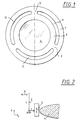
- the optics frame shown in principle in Figure 1 has a frame ring 1, which has three solid joints 2 is connected to an inner ring 3.
- the frame ring 1 and the inner ring 3 can be integrally formed his.
- the inner ring 3 carries a lens 4 as an optical element.
- the three solid joints 2 achieves voltage decoupling.
- the solid body hinge 7 with the two hinge parts 7a and 7b is connected on the outside to the mounting ring 1.
- On Slot 10 in a U-shape provides a separation of the rocker arm 5 from the mounting ring 1.
- At the upper end of the rocker arm 5 engages Via the slot 10, the drive member 6 on the rocker arm 5.
- the solid body pivot joint 8 is on the inside with the inner ring 3 connected and on the outside at the lower end, i.e. on that of that Point of attack of the drive member 6 facing away from the end Rocker arm 5 articulated. Through a circumferential slot 11, the is interrupted only by the solid-state rotary joints 7 and 8, the inner ring 3 is uncoupled from the mounting ring 1.
- the solid-state swivel joints can 7 and 8 due to the division of the solid body hinge 7 clearly in the two hinge parts 7a and 7b closer to each other than compared to an undivided form would be possible.
- the dimension l can accordingly be chosen smaller so that the transmission ratio l / L when the drive member 6 is actuated a drive, not shown, for moving the Inner ring 3 and thus the optical element 4 in the z direction becomes very large or sensitive.
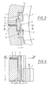
- the lever 12 is between the drive member 6 and the Rocker arm 5 a further lever ratio with a lever 12 arranged.
- the lever 12 is at one end as a storage point via an elastic solid body pivot joint 13 with the mounting ring 1 connected, while otherwise the lever 12 via a Slot 14 is separated from the mounting ring 1.
- the slot 14 must of course have such a width that at an actuation by the drive member 6 corresponding movements of the lever 12 are possible.
- At the end of the End region facing away from the solid-state rotary joint 13 engages the drive member 6 on.
- the further leverage is thus monolithic or in one piece with the socket 1.
- connection point 15 can also be different be trained. This applies e.g. for the direction of attack and its location
Landscapes
- Physics & Mathematics (AREA)
- General Physics & Mathematics (AREA)
- Optics & Photonics (AREA)
- Mounting And Adjusting Of Optical Elements (AREA)
- Lens Barrels (AREA)
- Pivots And Pivotal Connections (AREA)
- Transmission Devices (AREA)
- Chairs For Special Purposes, Such As Reclining Chairs (AREA)
Applications Claiming Priority (2)
| Application Number | Priority Date | Filing Date | Title |
|---|---|---|---|
| DE19908554 | 1999-02-27 | ||
| DE19908554A DE19908554A1 (de) | 1999-02-27 | 1999-02-27 | Verstellbare Baugruppe |
Publications (2)
| Publication Number | Publication Date |
|---|---|
| EP1031996A2 true EP1031996A2 (fr) | 2000-08-30 |
| EP1031996A3 EP1031996A3 (fr) | 2001-03-28 |
Family
ID=7899090
Family Applications (1)
| Application Number | Title | Priority Date | Filing Date |
|---|---|---|---|
| EP00103667A Withdrawn EP1031996A3 (fr) | 1999-02-27 | 2000-02-22 | Ensemble réglable |
Country Status (6)
| Country | Link |
|---|---|
| US (1) | US6259571B1 (fr) |
| EP (1) | EP1031996A3 (fr) |
| JP (1) | JP4489894B2 (fr) |
| KR (1) | KR100628410B1 (fr) |
| DE (1) | DE19908554A1 (fr) |
| TW (1) | TW538262B (fr) |
Cited By (5)
| Publication number | Priority date | Publication date | Assignee | Title |
|---|---|---|---|---|
| EP1035426A3 (fr) * | 1999-03-12 | 2004-06-30 | Carl Zeiss | Dispositif pour déplacer un élément optique le long de l'axe optique |
| WO2008009276A1 (fr) * | 2006-07-21 | 2008-01-24 | Jenoptik Laser, Optik, Systeme Gmbh | Monture réglable latéralement pour éléments optiques |
| WO2010072217A1 (fr) * | 2008-12-23 | 2010-07-01 | Jenoptik Laser, Optik, Systeme Gmbh | Monture optique monolithique |
| EP2255237A4 (fr) * | 2008-02-29 | 2013-01-23 | Corning Inc | Support optique cinématique |
| EP2927725A3 (fr) * | 2014-03-11 | 2016-01-13 | Ruag Space GmbH | Dispositif de positionnement pour applications de navigation spatiale |
Families Citing this family (33)
| Publication number | Priority date | Publication date | Assignee | Title |
|---|---|---|---|---|
| JP4945845B2 (ja) | 2000-03-31 | 2012-06-06 | 株式会社ニコン | 光学素子保持装置、鏡筒及び露光装置並びにマイクロデバイスの製造方法。 |
| KR100714927B1 (ko) | 2000-04-25 | 2007-05-07 | 에이에스엠엘 유에스, 인크. | 광학 시스템에서의 렌즈의 정밀 위치 설정 및 정렬을 위한장치, 시스템 및 방법 |
| JP4518630B2 (ja) * | 2000-06-20 | 2010-08-04 | 株式会社タムロン | レンズ鏡筒 |
| DE10030495A1 (de) | 2000-06-21 | 2002-01-03 | Zeiss Carl | Verfahren zum Verbinden einer Vielzahl von optischen Elementen mit einem Grundkörper |
| US6574053B1 (en) | 2000-08-10 | 2003-06-03 | Nikon Corporation | Kinematic alignment structure for placement between components axially aligned in a cylindrical body |
| EP1312965B1 (fr) * | 2000-08-18 | 2007-01-17 | Nikon Corporation | Dispositif de maintien d'element optique |
| DE10051706A1 (de) | 2000-10-18 | 2002-05-02 | Zeiss Carl | Vorrichtung zur Lagerung eines optischen Elementes |
| US6417976B1 (en) * | 2001-03-06 | 2002-07-09 | Terabeam Corporation | Apparatus and method to mount electro-optic systems |
| JP2002287023A (ja) | 2001-03-27 | 2002-10-03 | Nikon Corp | 投影光学系、該投影光学系を備えた投影露光装置及び投影露光方法 |
| DE10115915A1 (de) * | 2001-03-30 | 2002-10-02 | Zeiss Carl | Vorrichtung zur Justierung von Einrichtungen und zum Einstellen von Verstellwegen |
| DE10136387A1 (de) * | 2001-07-26 | 2003-02-13 | Zeiss Carl | Objektiv, insbesondere Objektiv für die Halbleiter-Lithographie |
| DE10140608A1 (de) * | 2001-08-18 | 2003-03-06 | Zeiss Carl | Vorrichtung zur Justage eines optischen Elements |
| DE10219514A1 (de) * | 2002-04-30 | 2003-11-13 | Zeiss Carl Smt Ag | Beleuchtungssystem, insbesondere für die EUV-Lithographie |
| JP4665759B2 (ja) * | 2003-06-06 | 2011-04-06 | 株式会社ニコン | 光学素子保持装置、鏡筒、露光装置、及びデバイスの製造方法 |
| DE10331390A1 (de) | 2003-07-11 | 2005-01-27 | Carl Zeiss Smt Ag | Verfahren zur Herstellung von asphärischen optischen Flächen |
| US6816325B1 (en) | 2003-09-11 | 2004-11-09 | Carl Zeiss Smt Ag | Mounting apparatus for an optical element |
| DE10344178B4 (de) * | 2003-09-24 | 2006-08-10 | Carl Zeiss Smt Ag | Halte- und Positioniervorrichtung für ein optisches Element |
| US7265917B2 (en) | 2003-12-23 | 2007-09-04 | Carl Zeiss Smt Ag | Replacement apparatus for an optical element |
| WO2005064382A1 (fr) * | 2003-12-25 | 2005-07-14 | Nikon Corporation | Appareil destine a supporter un element optique, cylindre, appareil d'exposition et procede de fabrication d'un dispositif |
| JP5165699B2 (ja) * | 2007-02-28 | 2013-03-21 | コーニング インコーポレイテッド | 一点の周囲に回動可能な光学マウント |
| DE102007014155A1 (de) * | 2007-03-20 | 2008-09-25 | Jenoptik Laser, Optik, Systeme Gmbh | Optikfassung und optisches Bauelement mit einer derartigen Optikfassung |
| DE102008000967B4 (de) * | 2008-04-03 | 2015-04-09 | Carl Zeiss Smt Gmbh | Projektionsbelichtungsanlage für die EUV-Mikrolithographie |
| USD651631S1 (en) * | 2010-12-01 | 2012-01-03 | Timothy Eugene Ovel | Lens gear |
| JP5935975B2 (ja) * | 2011-11-14 | 2016-06-15 | 株式会社ニコン | 光学部材位置調整装置、投影光学系及びその調整方法、並びに露光装置 |
| CN103472555B (zh) * | 2013-09-25 | 2016-06-01 | 中国科学院长春光学精密机械与物理研究所 | 双电机光学元件轴向调节装置 |
| DE102015101384B3 (de) * | 2015-01-30 | 2015-11-12 | Jenoptik Optical Systems Gmbh | Optische Fassung mit wenigstens einer Klemmeinheit mit einer Druckschraube |
| DE102015101385B3 (de) * | 2015-01-30 | 2016-01-21 | Jenoptik Optical Systems Gmbh | Optische Fassung mit wenigstens einer Klemmeinheit mit einer Zugschraube |
| DE102015101387B3 (de) * | 2015-01-30 | 2015-12-17 | Jenoptik Optical Systems Gmbh | Optische Fassung mit wenigstens einer Klemmeinheit mit einer Membranfeder |
| CN104749734B (zh) * | 2015-03-24 | 2017-04-05 | 中国科学院长春光学精密机械与物理研究所 | 一种光学元件轴向位置精密调整装置 |
| DE102015115929B3 (de) * | 2015-09-21 | 2016-10-06 | Jenoptik Optical Systems Gmbh | Monolithische Linsenfassung |
| DE102015223518A1 (de) * | 2015-11-27 | 2017-05-18 | Carl Zeiss Smt Gmbh | Optische Vorrichtung sowie Lithographieanlage |
| JP7373853B2 (ja) * | 2018-06-08 | 2023-11-06 | 株式会社nittoh | レンズ鏡筒およびレンズ交換式カメラ |
| DE102021208628A1 (de) * | 2021-08-09 | 2023-02-09 | Carl Zeiss Smt Gmbh | Abstützung eines optischen elements |
Family Cites Families (10)
| Publication number | Priority date | Publication date | Assignee | Title |
|---|---|---|---|---|
| JPS58111908A (ja) * | 1981-12-25 | 1983-07-04 | Canon Inc | 光学機器用レンズ鏡筒のレンズ保持装置 |
| NL8500615A (nl) * | 1985-03-05 | 1986-10-01 | Nederlanden Staat | Fijninstelmechanisme voor het nauwkeurig positioneren van een instelelement. |
| JPS62147413A (ja) * | 1985-12-20 | 1987-07-01 | Olympus Optical Co Ltd | レンズ保持装置 |
| DD278207A1 (de) * | 1988-12-19 | 1990-04-25 | Zeiss Jena Veb Carl | Fassung mit justierelementen |
| GB9017015D0 (en) * | 1990-08-02 | 1990-09-19 | British Telecomm | Optical component holder |
| US5428482A (en) | 1991-11-04 | 1995-06-27 | General Signal Corporation | Decoupled mount for optical element and stacked annuli assembly |
| JPH1054932A (ja) | 1996-08-08 | 1998-02-24 | Nikon Corp | 投影光学装置及びそれを装着した投影露光装置 |
| JPH10186198A (ja) * | 1996-12-25 | 1998-07-14 | Ushio Inc | 平行・真直微動装置およびこれを用いたレンズ鏡筒の微小移動装置 |
| EP0932064A1 (fr) | 1997-12-29 | 1999-07-28 | Perkin-Elmer Limited | Monture ajustable pour des composants optiques |
| DE19827603A1 (de) * | 1998-06-20 | 1999-12-23 | Zeiss Carl Fa | Optisches System, insbesondere Projektions-Belichtungsanlage der Mikrolithographie |
-
1999
- 1999-02-27 DE DE19908554A patent/DE19908554A1/de not_active Ceased
-
2000
- 2000-02-14 US US09/503,023 patent/US6259571B1/en not_active Expired - Lifetime
- 2000-02-22 EP EP00103667A patent/EP1031996A3/fr not_active Withdrawn
- 2000-02-22 KR KR1020000008429A patent/KR100628410B1/ko not_active Expired - Fee Related
- 2000-02-24 JP JP2000047169A patent/JP4489894B2/ja not_active Expired - Fee Related
- 2000-04-25 TW TW089103354A patent/TW538262B/zh not_active IP Right Cessation
Cited By (6)
| Publication number | Priority date | Publication date | Assignee | Title |
|---|---|---|---|---|
| EP1035426A3 (fr) * | 1999-03-12 | 2004-06-30 | Carl Zeiss | Dispositif pour déplacer un élément optique le long de l'axe optique |
| WO2008009276A1 (fr) * | 2006-07-21 | 2008-01-24 | Jenoptik Laser, Optik, Systeme Gmbh | Monture réglable latéralement pour éléments optiques |
| EP2255237A4 (fr) * | 2008-02-29 | 2013-01-23 | Corning Inc | Support optique cinématique |
| WO2010072217A1 (fr) * | 2008-12-23 | 2010-07-01 | Jenoptik Laser, Optik, Systeme Gmbh | Monture optique monolithique |
| US8547652B2 (en) | 2008-12-23 | 2013-10-01 | Jenoptik Optical Systems Gmbh | Monolithic optical mount |
| EP2927725A3 (fr) * | 2014-03-11 | 2016-01-13 | Ruag Space GmbH | Dispositif de positionnement pour applications de navigation spatiale |
Also Published As
| Publication number | Publication date |
|---|---|
| JP4489894B2 (ja) | 2010-06-23 |
| EP1031996A3 (fr) | 2001-03-28 |
| US6259571B1 (en) | 2001-07-10 |
| JP2000249886A (ja) | 2000-09-14 |
| TW538262B (en) | 2003-06-21 |
| KR100628410B1 (ko) | 2006-09-28 |
| KR20010014500A (ko) | 2001-02-26 |
| DE19908554A1 (de) | 2000-08-31 |
Similar Documents
| Publication | Publication Date | Title |
|---|---|---|
| EP1031996A2 (fr) | Ensemble réglable | |
| EP1020751B1 (fr) | Dispositif d'imagerie optique, en particulier objectif, avec au moins un élement optique | |
| DE3829022C2 (fr) | ||
| EP1182485B1 (fr) | Dispositif de réglage de la position relative de deux éléments | |
| EP1577693B1 (fr) | Objectif avec au moins un élément optique | |
| WO2002082096A2 (fr) | Detecteur | |
| DE69607732T2 (de) | Modulare Scheibenwischervorrichtung | |
| EP0539889A2 (fr) | Actionneur micromécanique | |
| WO2007087908A1 (fr) | Dispositif essuie-glace, notamment pour véhicule automobile | |
| DE2339534A1 (de) | Steuervorrichtung mit einem einzigen steuerhebel | |
| EP0920651B1 (fr) | Platine pour mise au point fine | |
| DE4226506B4 (de) | Lenkstockschalter für Kraftfahrzeuge | |
| WO2003081337A2 (fr) | Dispositif permettant de modifier la position angulaire d'un objet par rapport a une structure fixe | |
| DE102013109605B3 (de) | Optische Baugruppe mit einer monolithischen Fassung mit in einer gleichen Richtung wirkenden Stellschrauben | |
| DE20012046U1 (de) | Vorrichtung zum Justieren einer Fläche eines Justierteiles | |
| WO1999002831A1 (fr) | Dispositif pour deplacer un clapet de soupape | |
| DE102018118058A1 (de) | Head-up-Display mit spezifischer Halteklammer zum Halten eines Spiegels | |
| EP1375989B1 (fr) | Soupape piézoélectrique | |
| DE3411819C2 (fr) | ||
| DE19539581B4 (de) | Universalgelenk mit Feder-Viergelenken | |
| DE2805609C2 (fr) | ||
| DE19909965C2 (de) | Gangrastierung für eine Getriebeschaltung von Kraftfahrzeugen | |
| EP4109046B1 (fr) | Dispositif de mesure de position | |
| DE2151759C3 (de) | Außenrückblickspiegel für Fahrzeuge | |
| EP2072861A1 (fr) | Sécurité anti-rotation doté d'un égalisation de la tolérance |
Legal Events
| Date | Code | Title | Description |
|---|---|---|---|
| PUAI | Public reference made under article 153(3) epc to a published international application that has entered the european phase |
Free format text: ORIGINAL CODE: 0009012 |
|
| AK | Designated contracting states |
Kind code of ref document: A2 Designated state(s): DE FR GB IT NL |
|
| AX | Request for extension of the european patent |
Free format text: AL;LT;LV;MK;RO;SI |
|
| RIN1 | Information on inventor provided before grant (corrected) |
Inventor name: TRUNZ, MICHAEL Inventor name: POST, ALBERT, C/O PHILIPS CFT-MECHATRONICS Inventor name: TIMMERS, HUGO, C/O PHILIPS CFT-MECHATRONICS Inventor name: POLZER, THOMAS Inventor name: HOLDERER, HUBERT Inventor name: DRIES, JOHAN, C/O PHILIPS CFT-MECHATRONICS Inventor name: RUEMMER, PETER Inventor name: GEUPPERT, BERNHARD |
|
| K1C1 | Correction of patent application (title page) published |
Effective date: 20000830 |
|
| RIN1 | Information on inventor provided before grant (corrected) |
Inventor name: TIMMERS, HUGO, C/O PHILIPS CFT-MECHATRONICS Inventor name: DRIES, JOHAN, C/O PHILIPS CFT-MECHATRONICS Inventor name: POLZER, THOMAS Inventor name: POST, ALBERT, C/O PHILIPS CFT-MECHATRONICS Inventor name: HOLDERER, HUBERT Inventor name: TRUNZ, MICHAEL Inventor name: GEUPPERT, BERNHARD Inventor name: RUEMMER, PETER |
|
| PUAL | Search report despatched |
Free format text: ORIGINAL CODE: 0009013 |
|
| AK | Designated contracting states |
Kind code of ref document: A3 Designated state(s): AT BE CH CY DE DK ES FI FR GB GR IE IT LI LU MC NL PT SE |
|
| AX | Request for extension of the european patent |
Free format text: AL;LT;LV;MK;RO;SI |
|
| RIC1 | Information provided on ipc code assigned before grant |
Free format text: 7G 12B 5/00 A, 7G 02B 7/02 B |
|
| 17P | Request for examination filed |
Effective date: 20010626 |
|
| AKX | Designation fees paid |
Free format text: DE FR GB IT NL |
|
| RAP1 | Party data changed (applicant data changed or rights of an application transferred) |
Owner name: CARL ZEISS SMT AG |
|
| 17Q | First examination report despatched |
Effective date: 20070807 |
|
| RAP1 | Party data changed (applicant data changed or rights of an application transferred) |
Owner name: CARL ZEISS SMT AG |
|
| GRAP | Despatch of communication of intention to grant a patent |
Free format text: ORIGINAL CODE: EPIDOSNIGR1 |
|
| STAA | Information on the status of an ep patent application or granted ep patent |
Free format text: STATUS: THE APPLICATION IS DEEMED TO BE WITHDRAWN |
|
| 18D | Application deemed to be withdrawn |
Effective date: 20081111 |