EP1031996A3 - Adjustable assembly - Google Patents
Adjustable assembly Download PDFInfo
- Publication number
- EP1031996A3 EP1031996A3 EP00103667A EP00103667A EP1031996A3 EP 1031996 A3 EP1031996 A3 EP 1031996A3 EP 00103667 A EP00103667 A EP 00103667A EP 00103667 A EP00103667 A EP 00103667A EP 1031996 A3 EP1031996 A3 EP 1031996A3
- Authority
- EP
- European Patent Office
- Prior art keywords
- solid
- lever
- rocker arm
- base
- adjustable assembly
- Prior art date
- Legal status (The legal status is an assumption and is not a legal conclusion. Google has not performed a legal analysis and makes no representation as to the accuracy of the status listed.)
- Withdrawn
Links
- 239000007787 solid Substances 0.000 abstract 2
Classifications
-
- G—PHYSICS
- G12—INSTRUMENT DETAILS
- G12B—CONSTRUCTIONAL DETAILS OF INSTRUMENTS, OR COMPARABLE DETAILS OF OTHER APPARATUS, NOT OTHERWISE PROVIDED FOR
- G12B5/00—Adjusting position or attitude, e.g. level, of instruments or other apparatus, or of parts thereof; Compensating for the effects of tilting or acceleration, e.g. for optical apparatus
-
- G—PHYSICS
- G02—OPTICS
- G02B—OPTICAL ELEMENTS, SYSTEMS OR APPARATUS
- G02B7/00—Mountings, adjusting means, or light-tight connections, for optical elements
- G02B7/02—Mountings, adjusting means, or light-tight connections, for optical elements for lenses
- G02B7/023—Mountings, adjusting means, or light-tight connections, for optical elements for lenses permitting adjustment
-
- G—PHYSICS
- G02—OPTICS
- G02B—OPTICAL ELEMENTS, SYSTEMS OR APPARATUS
- G02B7/00—Mountings, adjusting means, or light-tight connections, for optical elements
- G02B7/02—Mountings, adjusting means, or light-tight connections, for optical elements for lenses
- G02B7/026—Mountings, adjusting means, or light-tight connections, for optical elements for lenses using retaining rings or springs
Landscapes
- Physics & Mathematics (AREA)
- General Physics & Mathematics (AREA)
- Optics & Photonics (AREA)
- Mounting And Adjusting Of Optical Elements (AREA)
- Lens Barrels (AREA)
- Pivots And Pivotal Connections (AREA)
- Transmission Devices (AREA)
- Chairs For Special Purposes, Such As Reclining Chairs (AREA)
Abstract
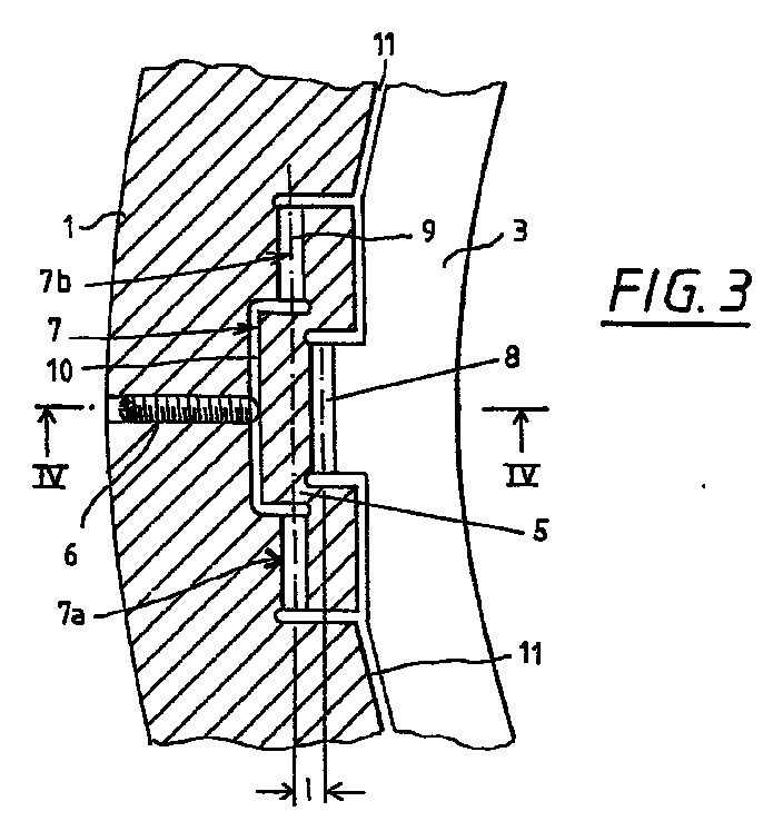
Eine verstellbare Baugruppe umfaßt eine Basis (Fassungsring 1),
einen verstellbaren Teil (Innenring 3), einen Hebel (Kipphebel
5) und einen Antrieb (Antriebsglied 6). Der Hebel (Kipphebel 5)
ist mit der Basis (Fassungsring 1) und dem verstellbaren Teil
(Innenring 3) über zwei parallel orientierte elastische Festkörperdrehgelenke
(7,8) verbunden. Eines der beiden Festkörperdrehgelenke
(7) ist in zwei Drehgelenkteile (7a,7b) aufgeteilt,
die entlang ihrer Drehachse (9) seitwärts versetzt beidseits
des zweiten Festkörperdrehgelenkes (8) angeordnet sind.
Applications Claiming Priority (2)
| Application Number | Priority Date | Filing Date | Title |
|---|---|---|---|
| DE19908554 | 1999-02-27 | ||
| DE19908554A DE19908554A1 (en) | 1999-02-27 | 1999-02-27 | Adjustable assembly |
Publications (2)
| Publication Number | Publication Date |
|---|---|
| EP1031996A2 EP1031996A2 (en) | 2000-08-30 |
| EP1031996A3 true EP1031996A3 (en) | 2001-03-28 |
Family
ID=7899090
Family Applications (1)
| Application Number | Title | Priority Date | Filing Date |
|---|---|---|---|
| EP00103667A Withdrawn EP1031996A3 (en) | 1999-02-27 | 2000-02-22 | Adjustable assembly |
Country Status (6)
| Country | Link |
|---|---|
| US (1) | US6259571B1 (en) |
| EP (1) | EP1031996A3 (en) |
| JP (1) | JP4489894B2 (en) |
| KR (1) | KR100628410B1 (en) |
| DE (1) | DE19908554A1 (en) |
| TW (1) | TW538262B (en) |
Families Citing this family (38)
| Publication number | Priority date | Publication date | Assignee | Title |
|---|---|---|---|---|
| DE19910947A1 (en) * | 1999-03-12 | 2000-09-14 | Zeiss Carl Fa | Device for moving an optical element along the optical axis |
| JP4945845B2 (en) | 2000-03-31 | 2012-06-06 | 株式会社ニコン | An optical element holding device, a lens barrel, an exposure apparatus, and a microdevice manufacturing method. |
| WO2001081970A2 (en) * | 2000-04-25 | 2001-11-01 | Silicon Valley Group, Inc. | Apparatus, system, and method for precision positioning and alignment of a lens in an optical system |
| JP4518630B2 (en) * | 2000-06-20 | 2010-08-04 | 株式会社タムロン | Lens barrel |
| DE10030495A1 (en) | 2000-06-21 | 2002-01-03 | Zeiss Carl | Method for connecting a plurality of optical elements to a base body |
| US6574053B1 (en) | 2000-08-10 | 2003-06-03 | Nikon Corporation | Kinematic alignment structure for placement between components axially aligned in a cylindrical body |
| DE60126103T2 (en) * | 2000-08-18 | 2007-11-15 | Nikon Corp. | Holding device for optical element |
| DE10051706A1 (en) * | 2000-10-18 | 2002-05-02 | Zeiss Carl | Device for supporting optical element, has approximately T-shaped joints with connection points between holders at outer ends of T-bearer and manipulators engaging T-support |
| US6417976B1 (en) * | 2001-03-06 | 2002-07-09 | Terabeam Corporation | Apparatus and method to mount electro-optic systems |
| JP2002287023A (en) | 2001-03-27 | 2002-10-03 | Nikon Corp | Projection optical system, projection exposure apparatus including the projection optical system, and projection exposure method |
| DE10115915A1 (en) * | 2001-03-30 | 2002-10-02 | Zeiss Carl | Device for adjusting devices and adjusting adjustment paths |
| DE10136387A1 (en) * | 2001-07-26 | 2003-02-13 | Zeiss Carl | Optical objective for semiconductor lithography has optical element with reflective reference surface used for adjustment relative to objective |
| DE10140608A1 (en) * | 2001-08-18 | 2003-03-06 | Zeiss Carl | Device for adjusting an optical element |
| DE10219514A1 (en) * | 2002-04-30 | 2003-11-13 | Zeiss Carl Smt Ag | Lighting system, especially for EUV lithography |
| CN100576003C (en) * | 2003-06-06 | 2009-12-30 | 株式会社尼康 | Optical element holding device, lens barrel, exposure device, and method for manufacturing apparatus |
| DE10331390A1 (en) | 2003-07-11 | 2005-01-27 | Carl Zeiss Smt Ag | Aspherical surface production process for optical elements, comprises placing element in mould, introducing medium, and spherically working deformed optical medium |
| US6816325B1 (en) | 2003-09-11 | 2004-11-09 | Carl Zeiss Smt Ag | Mounting apparatus for an optical element |
| DE10344178B4 (en) * | 2003-09-24 | 2006-08-10 | Carl Zeiss Smt Ag | Holding and positioning device for an optical element |
| US7265917B2 (en) | 2003-12-23 | 2007-09-04 | Carl Zeiss Smt Ag | Replacement apparatus for an optical element |
| US7697222B2 (en) * | 2003-12-25 | 2010-04-13 | Nikon Corporation | Apparatus for holding optical element, barrel, exposure apparatus, and device producing method |
| WO2008009276A1 (en) * | 2006-07-21 | 2008-01-24 | Jenoptik Laser, Optik, Systeme Gmbh | Laterally adjustable socket for optical elements |
| WO2008106182A1 (en) * | 2007-02-28 | 2008-09-04 | Corning Incorporated | Optical mount pivotable about a single point |
| DE102007014155A1 (en) * | 2007-03-20 | 2008-09-25 | Jenoptik Laser, Optik, Systeme Gmbh | Optics socket and optical component with such an optical socket |
| EP2255237B1 (en) * | 2008-02-29 | 2021-09-08 | Corning Incorporated | Kinematic optical mount |
| DE102008000967B4 (en) * | 2008-04-03 | 2015-04-09 | Carl Zeiss Smt Gmbh | Projection exposure machine for EUV microlithography |
| DE102008063223B3 (en) * | 2008-12-23 | 2010-09-09 | Jenoptik Laser, Optik, Systeme Gmbh | Monolithic optical socket |
| USD651631S1 (en) * | 2010-12-01 | 2012-01-03 | Timothy Eugene Ovel | Lens gear |
| JP5935975B2 (en) * | 2011-11-14 | 2016-06-15 | 株式会社ニコン | Optical member position adjusting device, projection optical system, adjusting method thereof, and exposure apparatus |
| CN103472555B (en) * | 2013-09-25 | 2016-06-01 | 中国科学院长春光学精密机械与物理研究所 | Dual-motor optical element axial adjustment device |
| AT515278B1 (en) * | 2014-03-11 | 2015-08-15 | Ruag Space Gmbh | Positioning device for space applications |
| DE102015101385B3 (en) * | 2015-01-30 | 2016-01-21 | Jenoptik Optical Systems Gmbh | Optical socket with at least one clamping unit with a lag screw |
| DE102015101387B3 (en) * | 2015-01-30 | 2015-12-17 | Jenoptik Optical Systems Gmbh | Optical socket with at least one clamping unit with a diaphragm spring |
| DE102015101384B3 (en) * | 2015-01-30 | 2015-11-12 | Jenoptik Optical Systems Gmbh | Optical socket with at least one clamping unit with a pressure screw |
| CN104749734B (en) * | 2015-03-24 | 2017-04-05 | 中国科学院长春光学精密机械与物理研究所 | A kind of optical element axial location precision adjustment unit |
| DE102015115929B3 (en) * | 2015-09-21 | 2016-10-06 | Jenoptik Optical Systems Gmbh | Monolithic lens frame |
| DE102015223518A1 (en) * | 2015-11-27 | 2017-05-18 | Carl Zeiss Smt Gmbh | Optical device and lithography system |
| EP3805829B1 (en) * | 2018-06-08 | 2024-08-21 | Nittoh Inc. | Lens barrel and interchangeable lens camera |
| DE102021208628A1 (en) * | 2021-08-09 | 2023-02-09 | Carl Zeiss Smt Gmbh | SUPPORT OF AN OPTICAL ELEMENT |
Citations (6)
| Publication number | Priority date | Publication date | Assignee | Title |
|---|---|---|---|---|
| DD278207A1 (en) * | 1988-12-19 | 1990-04-25 | Zeiss Jena Veb Carl | ASSEMBLY WITH ADJUSTING ELEMENTS |
| WO1992002837A1 (en) * | 1990-08-02 | 1992-02-20 | British Telecommunications Public Limited Company | Optical component holder |
| US5428482A (en) * | 1991-11-04 | 1995-06-27 | General Signal Corporation | Decoupled mount for optical element and stacked annuli assembly |
| JPH1054932A (en) * | 1996-08-08 | 1998-02-24 | Nikon Corp | Projection optical apparatus and projection exposure apparatus equipped with the same |
| JPH10186198A (en) * | 1996-12-25 | 1998-07-14 | Ushio Inc | Parallel / straight fine motion device and micro-movement device for lens barrel using the same |
| DE19827603A1 (en) * | 1998-06-20 | 1999-12-23 | Zeiss Carl Fa | Projection light exposure system for microlithography |
Family Cites Families (4)
| Publication number | Priority date | Publication date | Assignee | Title |
|---|---|---|---|---|
| JPS58111908A (en) * | 1981-12-25 | 1983-07-04 | Canon Inc | Lens holding device for lens barrels for optical equipment |
| NL8500615A (en) * | 1985-03-05 | 1986-10-01 | Nederlanden Staat | FINE ADJUSTMENT MECHANISM FOR PRECISE POSITIONING OF AN ADJUSTMENT ELEMENT. |
| JPS62147413A (en) * | 1985-12-20 | 1987-07-01 | Olympus Optical Co Ltd | Lens holding device |
| EP0932064A1 (en) | 1997-12-29 | 1999-07-28 | Perkin-Elmer Limited | Adjustable mounting of optical components |
-
1999
- 1999-02-27 DE DE19908554A patent/DE19908554A1/en not_active Ceased
-
2000
- 2000-02-14 US US09/503,023 patent/US6259571B1/en not_active Expired - Lifetime
- 2000-02-22 EP EP00103667A patent/EP1031996A3/en not_active Withdrawn
- 2000-02-22 KR KR1020000008429A patent/KR100628410B1/en not_active Expired - Fee Related
- 2000-02-24 JP JP2000047169A patent/JP4489894B2/en not_active Expired - Fee Related
- 2000-04-25 TW TW089103354A patent/TW538262B/en not_active IP Right Cessation
Patent Citations (6)
| Publication number | Priority date | Publication date | Assignee | Title |
|---|---|---|---|---|
| DD278207A1 (en) * | 1988-12-19 | 1990-04-25 | Zeiss Jena Veb Carl | ASSEMBLY WITH ADJUSTING ELEMENTS |
| WO1992002837A1 (en) * | 1990-08-02 | 1992-02-20 | British Telecommunications Public Limited Company | Optical component holder |
| US5428482A (en) * | 1991-11-04 | 1995-06-27 | General Signal Corporation | Decoupled mount for optical element and stacked annuli assembly |
| JPH1054932A (en) * | 1996-08-08 | 1998-02-24 | Nikon Corp | Projection optical apparatus and projection exposure apparatus equipped with the same |
| JPH10186198A (en) * | 1996-12-25 | 1998-07-14 | Ushio Inc | Parallel / straight fine motion device and micro-movement device for lens barrel using the same |
| DE19827603A1 (en) * | 1998-06-20 | 1999-12-23 | Zeiss Carl Fa | Projection light exposure system for microlithography |
Non-Patent Citations (2)
| Title |
|---|
| PATENT ABSTRACTS OF JAPAN vol. 1998, no. 06 30 April 1998 (1998-04-30) * |
| PATENT ABSTRACTS OF JAPAN vol. 1998, no. 12 31 October 1998 (1998-10-31) * |
Also Published As
| Publication number | Publication date |
|---|---|
| JP2000249886A (en) | 2000-09-14 |
| EP1031996A2 (en) | 2000-08-30 |
| JP4489894B2 (en) | 2010-06-23 |
| KR100628410B1 (en) | 2006-09-28 |
| KR20010014500A (en) | 2001-02-26 |
| DE19908554A1 (en) | 2000-08-31 |
| TW538262B (en) | 2003-06-21 |
| US6259571B1 (en) | 2001-07-10 |
Similar Documents
| Publication | Publication Date | Title |
|---|---|---|
| EP1031996A3 (en) | Adjustable assembly | |
| EP0671751A3 (en) | Ergonomic keyboard | |
| ATE444147T1 (en) | SUPPORT FOR ATTACHING A TOOL TO A DRIVE SHAFT AND ADAPTER FOR THIS | |
| AU8308891A (en) | Orthopaedic manipulator for reduction and external fixation | |
| EP1024267A3 (en) | Throttle valve rotation angle sensor | |
| HK1049521A1 (en) | High precision orientation alignment and gap control stages for imprint lithography processes | |
| EP1041318A3 (en) | Sealing ring | |
| EP1310688A3 (en) | Bearing | |
| EP0947655A3 (en) | Hinge with a base transversely adjustable by means of a cam | |
| DE60028035D1 (en) | MILLING FOR THE PREPARATION OF A TOOTH CROWNING TOOTHER | |
| EP0896188A3 (en) | Pivot for luminaire | |
| ATE159846T1 (en) | TOOTHBRUSH | |
| EP0839682A3 (en) | Control device | |
| DE59001587D1 (en) | PERFORMANCE DISC FOR CONNECTING DEVICES FOR SCAFFOLDING ELEMENTS. | |
| EP0360161A3 (en) | Device for dental treatment | |
| EP1046855A3 (en) | Quick-acting coupling | |
| EP1363031A3 (en) | Assembly for connecting pieces to elements made out of materials of a high degree of hardness | |
| EP1097754A3 (en) | Loop lifter | |
| EP1418067A3 (en) | Towing eye | |
| CA2195352A1 (en) | Cam Ram | |
| EP0774586A3 (en) | Fluid operated rotary actuator | |
| DE69821184D1 (en) | Straightening arrangement with two independent rotary movements and no dead center | |
| ATE324998T1 (en) | SWIRLING COLLAR CONSTRUCTION | |
| DE69702860D1 (en) | DEVICE FOR MOVING A PART OF A MACHINE AND APPLYING A FORCE AT THE END OF MOVEMENT | |
| DE50200304D1 (en) | Table arrangement with at least two table tops |
Legal Events
| Date | Code | Title | Description |
|---|---|---|---|
| PUAI | Public reference made under article 153(3) epc to a published international application that has entered the european phase |
Free format text: ORIGINAL CODE: 0009012 |
|
| AK | Designated contracting states |
Kind code of ref document: A2 Designated state(s): DE FR GB IT NL |
|
| AX | Request for extension of the european patent |
Free format text: AL;LT;LV;MK;RO;SI |
|
| RIN1 | Information on inventor provided before grant (corrected) |
Inventor name: TRUNZ, MICHAEL Inventor name: POST, ALBERT, C/O PHILIPS CFT-MECHATRONICS Inventor name: TIMMERS, HUGO, C/O PHILIPS CFT-MECHATRONICS Inventor name: POLZER, THOMAS Inventor name: HOLDERER, HUBERT Inventor name: DRIES, JOHAN, C/O PHILIPS CFT-MECHATRONICS Inventor name: RUEMMER, PETER Inventor name: GEUPPERT, BERNHARD |
|
| K1C1 | Correction of patent application (title page) published |
Effective date: 20000830 |
|
| RIN1 | Information on inventor provided before grant (corrected) |
Inventor name: TIMMERS, HUGO, C/O PHILIPS CFT-MECHATRONICS Inventor name: DRIES, JOHAN, C/O PHILIPS CFT-MECHATRONICS Inventor name: POLZER, THOMAS Inventor name: POST, ALBERT, C/O PHILIPS CFT-MECHATRONICS Inventor name: HOLDERER, HUBERT Inventor name: TRUNZ, MICHAEL Inventor name: GEUPPERT, BERNHARD Inventor name: RUEMMER, PETER |
|
| PUAL | Search report despatched |
Free format text: ORIGINAL CODE: 0009013 |
|
| AK | Designated contracting states |
Kind code of ref document: A3 Designated state(s): AT BE CH CY DE DK ES FI FR GB GR IE IT LI LU MC NL PT SE |
|
| AX | Request for extension of the european patent |
Free format text: AL;LT;LV;MK;RO;SI |
|
| RIC1 | Information provided on ipc code assigned before grant |
Free format text: 7G 12B 5/00 A, 7G 02B 7/02 B |
|
| 17P | Request for examination filed |
Effective date: 20010626 |
|
| AKX | Designation fees paid |
Free format text: DE FR GB IT NL |
|
| RAP1 | Party data changed (applicant data changed or rights of an application transferred) |
Owner name: CARL ZEISS SMT AG |
|
| 17Q | First examination report despatched |
Effective date: 20070807 |
|
| RAP1 | Party data changed (applicant data changed or rights of an application transferred) |
Owner name: CARL ZEISS SMT AG |
|
| GRAP | Despatch of communication of intention to grant a patent |
Free format text: ORIGINAL CODE: EPIDOSNIGR1 |
|
| STAA | Information on the status of an ep patent application or granted ep patent |
Free format text: STATUS: THE APPLICATION IS DEEMED TO BE WITHDRAWN |
|
| 18D | Application deemed to be withdrawn |
Effective date: 20081111 |