EP1032003A2 - Dispositif pour rendre étanche d'un boítier cylindrique d'huile d'un commutateur - Google Patents
Dispositif pour rendre étanche d'un boítier cylindrique d'huile d'un commutateur Download PDFInfo
- Publication number
- EP1032003A2 EP1032003A2 EP00103220A EP00103220A EP1032003A2 EP 1032003 A2 EP1032003 A2 EP 1032003A2 EP 00103220 A EP00103220 A EP 00103220A EP 00103220 A EP00103220 A EP 00103220A EP 1032003 A2 EP1032003 A2 EP 1032003A2
- Authority
- EP
- European Patent Office
- Prior art keywords
- insulating tube
- metal flange
- face
- screw
- sealing
- Prior art date
- Legal status (The legal status is an assumption and is not a legal conclusion. Google has not performed a legal analysis and makes no representation as to the accuracy of the status listed.)
- Granted
Links
- 238000007789 sealing Methods 0.000 title claims abstract description 20
- 229910052751 metal Inorganic materials 0.000 claims abstract description 25
- 239000002184 metal Substances 0.000 claims abstract description 25
- 230000001154 acute effect Effects 0.000 abstract description 5
- 239000000463 material Substances 0.000 description 3
- 230000000694 effects Effects 0.000 description 2
- 238000004519 manufacturing process Methods 0.000 description 2
- 230000007246 mechanism Effects 0.000 description 2
- 230000000712 assembly Effects 0.000 description 1
- 238000000429 assembly Methods 0.000 description 1
- 230000005540 biological transmission Effects 0.000 description 1
- 230000008859 change Effects 0.000 description 1
- 238000010276 construction Methods 0.000 description 1
- 238000001035 drying Methods 0.000 description 1
- 238000000034 method Methods 0.000 description 1
- 230000008569 process Effects 0.000 description 1
- WFKWXMTUELFFGS-UHFFFAOYSA-N tungsten Chemical compound [W] WFKWXMTUELFFGS-UHFFFAOYSA-N 0.000 description 1
- 229910052721 tungsten Inorganic materials 0.000 description 1
- 239000010937 tungsten Substances 0.000 description 1
Images
Classifications
-
- H—ELECTRICITY
- H01—ELECTRIC ELEMENTS
- H01H—ELECTRIC SWITCHES; RELAYS; SELECTORS; EMERGENCY PROTECTIVE DEVICES
- H01H9/00—Details of switching devices, not covered by groups H01H1/00 - H01H7/00
- H01H9/0005—Tap change devices
- H01H9/0044—Casings; Mountings; Disposition in transformer housing
-
- H—ELECTRICITY
- H01—ELECTRIC ELEMENTS
- H01F—MAGNETS; INDUCTANCES; TRANSFORMERS; SELECTION OF MATERIALS FOR THEIR MAGNETIC PROPERTIES
- H01F29/00—Variable transformers or inductances not covered by group H01F21/00
- H01F29/02—Variable transformers or inductances not covered by group H01F21/00 with tappings on coil or winding; with provision for rearrangement or interconnection of windings
- H01F29/025—Constructional details of transformers or reactors with tapping on coil or windings
-
- H—ELECTRICITY
- H01—ELECTRIC ELEMENTS
- H01H—ELECTRIC SWITCHES; RELAYS; SELECTORS; EMERGENCY PROTECTIVE DEVICES
- H01H33/00—High-tension or heavy-current switches with arc-extinguishing or arc-preventing means
- H01H33/02—Details
- H01H33/53—Cases; Reservoirs, tanks, piping or valves, for arc-extinguishing fluid; Accessories therefor, e.g. safety arrangements, pressure relief devices
- H01H33/55—Oil reservoirs or tanks; Lowering means therefor
-
- H—ELECTRICITY
- H01—ELECTRIC ELEMENTS
- H01H—ELECTRIC SWITCHES; RELAYS; SELECTORS; EMERGENCY PROTECTIVE DEVICES
- H01H9/00—Details of switching devices, not covered by groups H01H1/00 - H01H7/00
- H01H9/0005—Tap change devices
- H01H9/0044—Casings; Mountings; Disposition in transformer housing
- H01H2009/005—Details concerning the sealing of the oil filled casings
Definitions
- the invention relates to an arrangement for sealing a cylindrical Oil vessel of a switch, preferably a load selector, diverter switch for tap changer or the like, one in the boiler, especially in the oil boiler Transformer is provided and the oil vessel consists of an insulating tube, whose two end faces each have a metal flange of a cover or base part are assigned with a seal, the metal flange being detachable Clamping elements that engage in an outer groove of the insulating tube with the Insulating tube is connected.
- Such a sealing arrangement is known from AT-PS 341 624.
- External groove has a rectangular cross-section into which a ring shoulder of a Engages metal ring.
- This metal ring is over tension screws, which in a vertical threaded hole of the metal flange ends in the direction of Pulled the front of the insulating tube.
- This will also be the sealing rings between the face of the insulating cylinder and the metal flange compressed.
- a major disadvantage with this seal has been emphasized that due to the rectangular cross section of the outer groove an oversized thickness of the insulating tube must be selected.
- the rectangular cross-section causes a notch effect in the edges Can cause damage and can be compensated for with material thickness got to.
- the object of the invention is therefore to provide an arrangement of the type cited at the beginning to create, which on the one hand avoids the disadvantages indicated above and the on the other hand, rational production of such a switch is permitted.
- the arrangement according to the invention is characterized in that the outer groove of the insulating tube in cross section is semicircular that in this semicircular outer groove Round clamping ring is arranged in cross section and that in the metal flange at least one that runs at an acute angle to the end face of the insulating tube Threaded bore is provided with a screw, the end face of the Screw acts on the clamping ring.
- the semicircular outer groove in that facing away from its corresponding end face of the insulating tube Direction from the zenith to the outer circumference, especially at an angle trending, executed.
- This allows the clamping ring, even if it is in one piece is easy to use.
- This version also offers a good contact surface of the face of the screw on the clamping ring, since the Angle can be chosen relatively acute.
- the clamping ring consists of two Parts, in particular from two interconnectable half rings. Also this construction contributes to the simpler and therefore faster assembly. In addition, manufacturing tolerances can be compensated more easily.
- the screw is a Cylinder screw with a hexagon socket.
- Such machine elements have proven their worth in practice and do not require enlargement the storage of spare or assembly parts.
- 1 is an arrangement for sealing a cylindrical Oil tank of a load selector shown. Of course, this arrangement can Sealing can also be used when switching loads.
- Gearbox drives the selector shaft with all moving contacts.
- On Load selector combines the functions of a diverter switch and one Voters.
- the advantages of a load selector are that universal as Star point switch, single pole switch or can be used as a delta switch. He has a simple mechanism, with all switching contacts made of sintered tungsten material can be produced. This choice of materials is one to achieve long contact life.
- a load selector can also be separate Have continuous current contacts.
- the drive shaft is or are and the flange connections are freely adjustable.
- the load selector changes the levels directly during the dialing process. As soon as the motor drive starts, the transmission starts in the switch head Spring mechanism. After the complete opening, the lock is released the spring accumulator lifted and this actuates the movable Contact system of the load selector in quick changeover from the selected to the selected level.
- the changeover time is approx. 40 to 60 ms.
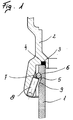
- This oil vessel consists of an insulating tube 1, being on its end face a metal flange 2 of a cover part is arranged.
- the sealing takes place via a sealing ring 3 which between the end face of the insulating cylinder 1 and the metal flange 2 is provided.
- This sealing ring 3 is, for example, in a ring groove 4 of the metal flange 2 specially dimensioned for him arranged.
- the insulating tube 1 has an outer groove 5 in which a clamping ring 6 is arranged. Furthermore, in the metal flange 2 at an acute angle to the end face of the insulating tube 1, a threaded bore 7 is provided with a screw 8. The end face of the screw 8 acts on the clamping ring 6.
- the clamping ring 6 can consist of two parts, in particular of two together connectable half rings.
- the screw 8 a Socket head screw with a hexagon socket.
- the outer groove 5 is in its corresponding Direction facing obliquely. This slant 9 also serves for easier assembly of the clamping ring 6.
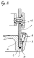
- the metal flange 2 is the seal of the metal flange 2, the bottom part Used, shown.
- the metal flange 2 again has the annular groove 4 for the sealing ring 3, which is arranged on the end face of the insulating tube 1. Furthermore, the metal flange 2 has an acute angle to the end face of the Insulating tube 1 running threaded hole 7 with a screw 8. In the External groove 5, the clamping ring 6 is provided on the end face of the Screw 8 acts.
- the bottom part can be vertical for easier emptying of the oil container Have holes 10.
Landscapes
- Engineering & Computer Science (AREA)
- Power Engineering (AREA)
- Driving Mechanisms And Operating Circuits Of Arc-Extinguishing High-Tension Switches (AREA)
- Housings And Mounting Of Transformers (AREA)
- Manufacture Of Switches (AREA)
- Switch Cases, Indication, And Locking (AREA)
- Gas-Insulated Switchgears (AREA)
- Level Indicators Using A Float (AREA)
- Push-Button Switches (AREA)
- Insulators (AREA)
Priority Applications (1)
| Application Number | Priority Date | Filing Date | Title |
|---|---|---|---|
| AT00103220T ATE327563T1 (de) | 1999-02-24 | 2000-02-17 | Anordnung zur abdichtung eines zylindrischen olgefässes eines schalters |
Applications Claiming Priority (2)
| Application Number | Priority Date | Filing Date | Title |
|---|---|---|---|
| AT31499 | 1999-02-24 | ||
| AT0031499A AT409563B (de) | 1999-02-24 | 1999-02-24 | Anordnung zur abdichtung eines zylindrischen ölgefässes eines schalters |
Publications (3)
| Publication Number | Publication Date |
|---|---|
| EP1032003A2 true EP1032003A2 (fr) | 2000-08-30 |
| EP1032003A3 EP1032003A3 (fr) | 2001-05-02 |
| EP1032003B1 EP1032003B1 (fr) | 2006-05-24 |
Family
ID=3487291
Family Applications (1)
| Application Number | Title | Priority Date | Filing Date |
|---|---|---|---|
| EP00103220A Expired - Lifetime EP1032003B1 (fr) | 1999-02-24 | 2000-02-17 | Dispositif d'étanchéité d'un réservoir d'huile cylindrique pour un commutateur |
Country Status (3)
| Country | Link |
|---|---|
| EP (1) | EP1032003B1 (fr) |
| AT (2) | AT409563B (fr) |
| DE (1) | DE50012796D1 (fr) |
Cited By (2)
| Publication number | Priority date | Publication date | Assignee | Title |
|---|---|---|---|---|
| EP1211771A1 (fr) * | 2000-11-30 | 2002-06-05 | Mitsubishi Denki Kabushiki Kaisha | Installation de commutation à isolation gazeuse |
| EP3761332A1 (fr) * | 2019-07-01 | 2021-01-06 | ABB Power Grids Switzerland AG | Changeur de prise en charge comprenant une barrière d'isolation |
Families Citing this family (2)
| Publication number | Priority date | Publication date | Assignee | Title |
|---|---|---|---|---|
| DE102012103490B4 (de) * | 2012-04-20 | 2015-11-12 | Maschinenfabrik Reinhausen Gmbh | Verteiltransformator zur Spannungsregelung von Ortsnetzen |
| DE102012103489B4 (de) * | 2012-04-20 | 2015-11-12 | Maschinenfabrik Reinhausen Gmbh | Laststufenschalter und dessen Verwendung zur Spannungsregelung in einem Verteiltransformator |
Family Cites Families (2)
| Publication number | Priority date | Publication date | Assignee | Title |
|---|---|---|---|---|
| GB584834A (en) * | 1945-01-29 | 1947-01-23 | Crabtree & Co Ltd J A | Improvements in and connected with electric switches having oil-immersed contacts |
| AT341624B (de) * | 1975-09-29 | 1978-02-27 | Elin Union Ag | Abdichtungsanordnung fur ein zylindrisches olgefass eines lastumschalters fur stufenschalter |
-
1999
- 1999-02-24 AT AT0031499A patent/AT409563B/de not_active IP Right Cessation
-
2000
- 2000-02-17 AT AT00103220T patent/ATE327563T1/de not_active IP Right Cessation
- 2000-02-17 DE DE50012796T patent/DE50012796D1/de not_active Expired - Fee Related
- 2000-02-17 EP EP00103220A patent/EP1032003B1/fr not_active Expired - Lifetime
Cited By (4)
| Publication number | Priority date | Publication date | Assignee | Title |
|---|---|---|---|---|
| EP1211771A1 (fr) * | 2000-11-30 | 2002-06-05 | Mitsubishi Denki Kabushiki Kaisha | Installation de commutation à isolation gazeuse |
| US6504125B2 (en) | 2000-11-30 | 2003-01-07 | Mitsubishi Denki Kabushiki Kaisha | Gas-filled switching apparatus |
| EP3761332A1 (fr) * | 2019-07-01 | 2021-01-06 | ABB Power Grids Switzerland AG | Changeur de prise en charge comprenant une barrière d'isolation |
| WO2021001275A1 (fr) * | 2019-07-01 | 2021-01-07 | Abb Power Grids Switzerland Ag | Changeur de prise en charge comprenant une barrière d'isolation |
Also Published As
| Publication number | Publication date |
|---|---|
| ATE327563T1 (de) | 2006-06-15 |
| EP1032003B1 (fr) | 2006-05-24 |
| ATA31499A (de) | 2002-01-15 |
| AT409563B (de) | 2002-09-25 |
| EP1032003A3 (fr) | 2001-05-02 |
| DE50012796D1 (de) | 2006-06-29 |
Similar Documents
| Publication | Publication Date | Title |
|---|---|---|
| DE3334159C2 (fr) | ||
| DE2733195A1 (de) | Ventileinrichtung | |
| DE4425540C2 (de) | Modulares Ventil für strömende Medien | |
| WO2018210892A1 (fr) | Passage de câble | |
| CH697751B1 (de) | Tragbarer Apparat, insbesondere tragbarer Zeitmesser. | |
| EP0305821A1 (fr) | Dispositif pour fermer l'embranchement d'un tube | |
| DE2843370C2 (de) | Wasserhahn | |
| EP1032003A2 (fr) | Dispositif pour rendre étanche d'un boítier cylindrique d'huile d'un commutateur | |
| DE3320193C2 (de) | Türbeschlag | |
| DE3902326A1 (de) | Elektromotor | |
| AT4808U2 (de) | Anordnung zur abdichtung eines zylindrischen ölgefässes eines schalters | |
| DE3532988C2 (de) | Elektrohydraulische Schaltvorrichtung | |
| EP0855544A2 (fr) | Mitigeur monocommande | |
| EP1527295B1 (fr) | Robinet a boisseau spherique a trois voies | |
| DE2720047A1 (de) | Mischventil fuer heiss- und kaltwasser | |
| DE3216371C2 (fr) | ||
| EP0102443A1 (fr) | Tiroir à voies multiples | |
| DE8903890U1 (de) | Ventil für das Abgeben von Kalt- oder Warmwasser | |
| DE9002502U1 (de) | Vorreiberverschluß | |
| DE7722015U1 (de) | Drosselklappe | |
| DE2826886A1 (de) | Mehrfach-stufendrehschalter | |
| DE2922580A1 (de) | Mischventil | |
| DE8520327U1 (de) | Installationsgerät mit Rohrnieten | |
| DD233404A5 (de) | Vorrichtung zur verriegelung einer armatur | |
| DE3330819A1 (de) | Vorrichtung zum absperren einer oeffnung |
Legal Events
| Date | Code | Title | Description |
|---|---|---|---|
| PUAI | Public reference made under article 153(3) epc to a published international application that has entered the european phase |
Free format text: ORIGINAL CODE: 0009012 |
|
| AK | Designated contracting states |
Kind code of ref document: A2 Designated state(s): AT DE SE |
|
| AX | Request for extension of the european patent |
Free format text: AL;LT;LV;MK;RO;SI |
|
| PUAL | Search report despatched |
Free format text: ORIGINAL CODE: 0009013 |
|
| AK | Designated contracting states |
Kind code of ref document: A3 Designated state(s): AT BE CH CY DE DK ES FI FR GB GR IE IT LI LU MC NL PT SE |
|
| AX | Request for extension of the european patent |
Free format text: AL;LT;LV;MK;RO;SI |
|
| 17P | Request for examination filed |
Effective date: 20011026 |
|
| AKX | Designation fees paid |
Free format text: AT DE SE |
|
| RAP1 | Party data changed (applicant data changed or rights of an application transferred) |
Owner name: MASCHINENFABRIK REINHAUSEN GMBH |
|
| GRAP | Despatch of communication of intention to grant a patent |
Free format text: ORIGINAL CODE: EPIDOSNIGR1 |
|
| RIN1 | Information on inventor provided before grant (corrected) |
Inventor name: STROF, THOMAS, DIPL.-ING. DR. |
|
| GRAS | Grant fee paid |
Free format text: ORIGINAL CODE: EPIDOSNIGR3 |
|
| GRAA | (expected) grant |
Free format text: ORIGINAL CODE: 0009210 |
|
| AK | Designated contracting states |
Kind code of ref document: B1 Designated state(s): AT DE SE |
|
| REG | Reference to a national code |
Ref country code: SE Ref legal event code: TRGR |
|
| REF | Corresponds to: |
Ref document number: 50012796 Country of ref document: DE Date of ref document: 20060629 Kind code of ref document: P |
|
| PG25 | Lapsed in a contracting state [announced via postgrant information from national office to epo] |
Ref country code: SE Free format text: LAPSE BECAUSE OF NON-PAYMENT OF DUE FEES Effective date: 20070218 |
|
| PLBE | No opposition filed within time limit |
Free format text: ORIGINAL CODE: 0009261 |
|
| STAA | Information on the status of an ep patent application or granted ep patent |
Free format text: STATUS: NO OPPOSITION FILED WITHIN TIME LIMIT |
|
| 26N | No opposition filed |
Effective date: 20070227 |
|
| EUG | Se: european patent has lapsed | ||
| PG25 | Lapsed in a contracting state [announced via postgrant information from national office to epo] |
Ref country code: DE Free format text: LAPSE BECAUSE OF NON-PAYMENT OF DUE FEES Effective date: 20070901 |
|
| PG25 | Lapsed in a contracting state [announced via postgrant information from national office to epo] |
Ref country code: AT Free format text: LAPSE BECAUSE OF NON-PAYMENT OF DUE FEES Effective date: 20070217 |