EP1032005A2 - Installation électrique - Google Patents
Installation électrique Download PDFInfo
- Publication number
- EP1032005A2 EP1032005A2 EP00103259A EP00103259A EP1032005A2 EP 1032005 A2 EP1032005 A2 EP 1032005A2 EP 00103259 A EP00103259 A EP 00103259A EP 00103259 A EP00103259 A EP 00103259A EP 1032005 A2 EP1032005 A2 EP 1032005A2
- Authority
- EP
- European Patent Office
- Prior art keywords
- plug
- module
- electrical system
- contact
- electrical
- Prior art date
- Legal status (The legal status is an assumption and is not a legal conclusion. Google has not performed a legal analysis and makes no representation as to the accuracy of the status listed.)
- Granted
Links
Images


Classifications
-
- H—ELECTRICITY
- H01—ELECTRIC ELEMENTS
- H01H—ELECTRIC SWITCHES; RELAYS; SELECTORS; EMERGENCY PROTECTIVE DEVICES
- H01H85/00—Protective devices in which the current flows through a part of fusible material and this current is interrupted by displacement of the fusible material when this current becomes excessive
- H01H85/54—Protective devices wherein the fuse is carried, held, or retained by an intermediate or auxiliary part removable from the base, or used as sectionalisers
- H01H85/62—Protective devices wherein the fuse is carried, held, or retained by an intermediate or auxiliary part removable from the base, or used as sectionalisers the intermediate or auxiliary part being adapted for screwing into the base
-
- H—ELECTRICITY
- H01—ELECTRIC ELEMENTS
- H01H—ELECTRIC SWITCHES; RELAYS; SELECTORS; EMERGENCY PROTECTIVE DEVICES
- H01H9/00—Details of switching devices, not covered by groups H01H1/00 - H01H7/00
- H01H9/10—Adaptation for built-in fuses
- H01H9/102—Fuses mounted on or constituting the movable contact parts of the switch
-
- H—ELECTRICITY
- H01—ELECTRIC ELEMENTS
- H01H—ELECTRIC SWITCHES; RELAYS; SELECTORS; EMERGENCY PROTECTIVE DEVICES
- H01H85/00—Protective devices in which the current flows through a part of fusible material and this current is interrupted by displacement of the fusible material when this current becomes excessive
- H01H85/54—Protective devices wherein the fuse is carried, held, or retained by an intermediate or auxiliary part removable from the base, or used as sectionalisers
- H01H85/547—Protective devices wherein the fuse is carried, held, or retained by an intermediate or auxiliary part removable from the base, or used as sectionalisers with sliding fuse carrier
-
- H—ELECTRICITY
- H01—ELECTRIC ELEMENTS
- H01H—ELECTRIC SWITCHES; RELAYS; SELECTORS; EMERGENCY PROTECTIVE DEVICES
- H01H9/00—Details of switching devices, not covered by groups H01H1/00 - H01H7/00
- H01H9/02—Bases, casings, or covers
- H01H9/04—Dustproof, splashproof, drip-proof, waterproof, or flameproof casings
Definitions
- the invention relates to an electrical system with at least one control electronics and a system module that can be connected to this, in an electrical connecting line at least one switching device between the control electronics and the system module and a fuse and terminals for connecting the system module to the electrical Connection line are arranged.
- Such an electrical system must be started before maintenance work, repairs or the like are switched off. This is done via the switching device, which interrupts the electrical connection between the system module and control electronics.
- the system module can then be serviced or replaced, for example or other components between the fuse electronics and the system module serviced or replaced.
- Such a voltage isolation of the electrical system is particularly in such Areas where there is a risk of explosion, i.e. in so-called Ex areas.
- the invention lies in view of the prior art known from practice the task of an electrical system of the type mentioned to improve that this is simplified and switch off the electrical System is avoided as much as possible, with the electrical system simultaneously is cheaper to manufacture and operate.
- This task is related to the features of the preamble of the claim 1 solved in that the fuse is arranged in a plug-in module, which is detachably plugged into a base part, the first clamp for connecting the system module and second terminals for connecting the control electronics, one electrical connection between the first and second terminals via the inserted Plug-in module is formed.
- the plug-in module can be easily secured with Base part can be solved, which already creates the electrical connection between control electronics and system module is interrupted. By removing the plug-in module only this electrical connection is interrupted and not the entire one System or larger system parts are switched off. By arranging the Clamps in or on the base part, this also serves for electrical connection of the system module and the control electronics, so that separately arranged terminals can be omitted. Because of this simple way of de-energizing, you can individual system modules for maintenance purposes, repairs or the like quickly and safely disconnected from the electrical system.
- the plug-in module is also very compact and can be carried by maintenance personnel to prevent the system module from being accidentally switched on again. This is particularly important if the system module is relatively far away is arranged by base part and plug-in module, which is usually the case.
- the plug-in module When used in hazardous areas, it is also important that the corresponding system module is selected first is switched off and only then is the fuse completely removed becomes.
- the plug-in module simultaneously can be arranged as a switching device in at least two positions relative to the base part is, system module and control electronics in the first connection position electrically connected and electrically separated from one another in the second disconnected position are. This means that the plug-in module is first moved from the connection position to the disconnected position moved, whereby the system module is de-energized.
- Ignitable sparks that can occur when this voltage is disconnected are corresponding EN 50018 are flameproof and are then removed before they are actually removed cool down the plug-in module. Only then will the plug-in module become his Separation position removed and separated from the base part. In this way, the invention no additional arrangement of a switching device necessary, because of the removal of the plug-in module a voltage isolation of the corresponding system module should be done.
- control electronics and base part as well can be arranged in this plug-in module in a control cabinet. It is it goes without saying that a large number of such components are contained in the control cabinet could be.
- the corresponding system modules, such as sensors or the like, can be located far away from the control cabinet on site in the hazardous area and via appropriate connection lines, such as electrical wiring, Bus systems or the like with the control cabinet and accordingly with a base part and control electronics.
- the base part can have at least one support terminal for the serial connection of two system modules.
- standardized rails are provided through which the components are held and to which the components can be easily attached.
- the base part have a base housing that can be snapped onto such a DIN rail, for example is.
- Other connections between the base part or base housing and Rail are obvious.
- a snap fastening device can be used to easily implement such a snap connection be arranged on a rear side of the base housing.
- base housing An easily accessible and simply constructed base housing can be seen in it be that this is a trough-like lower part and a closing this, in particular has lockable base cover.
- Clamps can preferably be arranged directly in the base cover.
- the plug-in module can be easily plugged in, at least an insertion device can be arranged in the base cover, in which the plug-in module a mating device detachable and connecting system module and control electronics is insertable.
- the insertion device can be constructed in a variety of ways. With a simple one For example, it can have a double socket, into which plug pins projecting outwards from the plug-in module can be inserted.
- the plug connection between the plug-in module and the base part in the Type of protection "flameproof encapsulation” must be carried out, since no other types of protection Allow plugging under load in the Ex area, except in circuits of the type of protection "Intrinsically safe”. Therefore, the double socket or the plug-in device is pressure-resistant encapsulated (EN 50018), such a connector can also be used if there is one explosive mixture in the area of the electrical system.
- the base part can have a latching device with which the plug-in module is releasably locked in the connection and disconnection position and by which both positions are determined at the same time.
- such a latching device can have two on top of each other Assigning locking arms projecting outwards from the base cover with locking projections arranged on opposite outer sides of the plug-in module are plantable. It should be noted again that this type of locking device ensures that the system module is only switched off in the disconnected position and then remove the plug-in module from the disconnected position from the base part can.
- a simple and inexpensive plug-in module can be realized in that this has a box-shaped plug-in housing that points away from the base part Front can be closed by a lid.
- the plug-in module is the Securing in a manner known per se, for example between two resilient contacts held.
- the terminals can be used to connect the system module and Control electronics can be arranged directly in the base cover.
- plug-in housings and / or base housing have terminal covers for the terminals.
- the terminals can only be reached after removing the terminal covers, which easily meets the requirements of accident prevention protection become. If such a clamp cover is connected to the plug housing, be the terminals are released by removing the plug-in module and are then accessible.
- To easily establish an electrical connection between the terminals for the system module and control electronics within the base part can produce electrical Connection lines between the terminals and the plug-in device in the Base housing to be arranged.
- At least one terminal cover is formed in one piece with the cover, so that at least some of the terminals are released directly when the plug-in module is removed become.
- the insertion device can be used as be pressure-resistant capsule formed in the electrically connectable to the terminals Contact elements are arranged spaced from one another, an electrical Connection of the contact elements by a movable insert into the capsule Contact pin can be produced.
- An electrical connection to that contained in the plug-in module Fuse can be separately, for example, in the previously described Way.
- the contact pin can be removed from the plug-in module protrude.
- the plug-in module again by moving the plug-in module out of the Connection position in the disconnected position of the contact pin relative to the contact elements in the capsule so far that the electrical connection is disconnected.
- the plug-in module can then be carried to a random Avoid reinserting into the connection position.
- the contact pin To move the contact pin before moving the plug-in module from the connection position to To move the separation position, the contact pin with a particular from the front of the plug-in housing or its cover, the actuating element projecting from the movement his. The contact pin is then so far over this actuator adjustable relative to the contact elements so that the electrical connection is separated becomes. Then, for example, the plug-in module can then be completely removed from the base part or at least in the above-mentioned separation position.
- the actuator for example, an electrically insulating part of the Can be contact pin, which part at least partially protrudes from the plug-in module.
- a simple design of contact elements which can be electrically connected to the contact pin arises, for example, when the contact elements from above one another the cap arranged contact rings are formed. In the voltage release position the contact pin is only in contact with one of these contact rings and in the voltage connection position it establishes contact between the two contact rings. These, in turn, are carried out in the same way as previously, with the terminals electrically connected for connecting the system module and control electronics.
- the plug-in module can be a sleeve-shaped one Have lower part and a detachably attachable cap, the with the terminals electrically connected contact elements arranged in the lower part and at attached cap are connected via the fuse detachably held in the cap.
- the cap with the fuse is removed if the power is disconnected of the system module is desired.
- the lower part of the plug-in module with the ones arranged in it Contact elements can remain on the base part.
- the electrical contact to the plug-in module takes place, for example, in that the first contact element directly with a connection contact of the fuse and the second contact element via a mating contact element arranged within the cap with the other connection contact the fuse is connected.
- the cap In order not to directly close the inside of the plug-in module when separating the cap and lower part open, the cap can be inserted into the lower part, open inner sleeve have, which at its lower end has an external thread for screwing with a has internal threads formed within the lower part.
- the cylindrical The gap between the inner sleeve and the lower part forms the gap for the pressure-resistant encapsulation.
- the second contact element on an inside of the inner sleeve have adjacent sliding contact element.
- the mating contact element can be on the inside applied abrasive counter-contact element extending over part of the inner circumference and one of these to the other connection contact of the fuse extend connecting contact element.
- the electrical connection exists thereby as long as the sliding contact element and the sliding counter contact element are in contact are.
- connection contact element in the area of the other connection contact of the fuse an elastic Plug-in holder forms. This is used to releasably hold one end of the fuse, which means that even when the cap is detached from the lower part, it is securely in the cap held and is manageable with this.
- this can be spring loaded in the direction of securing his.
- the first contact element be arranged within the lower part in a pressure-resistant chamber from which a contact pin protrudes towards the fuse. It should be noted that the smaller the volume of the flameproof enclosure, the simpler the practical implementation. The circuit is therefore initially interrupted in this separate one flameproof chamber before further contact between the cap and base interrupted by their relative rotation to each other.
- the Contact pin movably mounted relative to the first contact element and towards the fuse be spring loaded.
- the contact pin is separated from the first contact element and device finally in contact with a wall of the chamber, whereupon by further unscrewing the cap also the contact between the contact pin and fuse is interrupted becomes.
- this can be rotatably supported on the cap. Thereby is a free rotation of the cap relative to the terminal cover to loosen the Cap from the lower part possible and after loosening the terminal cover can be put together be removed with the cap.
- a simple rotatable mounting of the terminal cover on the cap is for example can be realized in that the terminal cover has an annular flange which at least partially inserted rotatably in an annular groove in the outer circumference of the cap is.
- the plug-in module and base part according to the invention are compact and relatively small educated. However, it is still possible, if necessary, further electrical and / or electronic components, such as bus terminating resistor, voltage display, Current display, polarity indicator or the like in the plug-in module and / or in the base part to arrange.
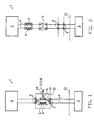
- Fig. 1 is a schematic representation of a system 1 according to the invention with at least a control electronics 2, a system module 3 and a plug-in module 9 with a base part 10, wherein the plug-in module and base part are simultaneously a switching device 5 form.
- the electrical system 1 can be similar to other of these components Have arrangement.
- Control electronics 2 as well as plug-in module 9 and base part 10 are generally in one Control cabinet 13 arranged.
- the electrical connection between control electronics 2 and system module 3 takes place via electrical connecting lines 4, plug-in module and base part are arranged in the electrical connection line.
- the electrical Connection line 4 can be formed by individual cables, a bus system or the like his.
- the base part 10 is detachably fastened within the control cabinet 13 and by this the plug-in module 9 with fuses 6 can be separated, see line 69 in FIG. 1.
- first and second terminals 7, 8 are provided, on the system module 3 and control electronics 2 can be connected and are electrically connected when the plug-in module 9 is inserted.
- Another clamp 14 is a so-called support clamp between each of the first and second terminals 7, 8 are provided, see FIG. 3.
- FIG. 2 shows an electrical system 1 according to the prior art. With this are in the electrical lines 4 between the control electronics 2 and system module 3 Arranged a number of different components. One component is a fuse box with two fuses 6. Another component is a switching device 5 for interrupting the electrical connection lines 4. Finally, inside the cabinet 13 also first and second terminals 7, 8 on the electrical connecting lines 4 provided, via which a voltage supply through further electrical lines takes place within the control cabinet 13.
- Fig. 3 the electrical system according to Fig. 1 is partially shown, by means of the first Terminals 7 and the support terminal 14 arranged in between two system modules 3, 15 are connected to the base part 10 via electrical lines. To this In this way, the system modules can be protected selectively and individually with parallel supply be disconnected from the voltage.
- FIG. 4 is a section along the line I-I of Fig. 1 through a first embodiment represented by plug-in module 9 and base part 10. As stated above, form Plug-in module and base part simultaneously a switching device 5 for interruption the power supply.
- the base part 10 is by a base housing 16 made of tub-like lower part 20 and Base cover 21 formed.
- the lower part 20 has on its opposite the plug-in module 9 Back 19 a snap fastening device 18 for detachable fastening of the lower part 10 on a DIN rail 17.
- the base cover 21 is detachably connected to the lower part 20 at the open end thereof and locked there.
- Known terminals 7, 8 are in the base cover 21 arranged. These are via electrical connecting lines 39 with contacts one Plug-in device 22 connected in the form of a double socket 24.
- the insertion device 22 is a mating device 23 protruding from the plug-in module 9 detachably inserted.
- this plug pins 25 are arranged, which from the plug-in module 9 in Project towards base part 10. Laterally spaced on both sides to the plug-in device 22 protrude from the base cover 21 locking arms 27, 28 as a locking device 26. These point towards one another and engage behind from outside 29, 30 of the plug-in module 9 protruding locking projections 31.
- Plug module 9 arranged in its connecting position 11. In this the on behind the base cover 21 spaced-apart locking projections 31 behind.
- the plug-in module 9 is formed by a box-shaped plug housing 32 with a cover 34. In a rear side of the plug housing 32 facing the base cover 21 in the plug-in recesses 36, the mating plug-in devices 23 with the plug pins 25 arranged. These engage with the plug-in device 22 when in the connecting position 11 arranged plug-in module 9.
- the cover 34 of the plug-in module 9 has a one-piece terminal cover 38 on one side to which extends in steps over the locking arm 28 and the second terminals 8 and covers them.
- a second terminal cover 37 covers the first terminals 7 opposite the plug-in module 9, both terminal covers 37, 38 can be formed in one piece with the plug-in module 9.
- the locking projections 31 protrude from outer sides 29, 30 of the plug housing 32.
- Plug-in device 22 in plug-in device 23 formed plug connections in the type of protection "flameproof enclosure”. Allow other types of protection No plugging in the Ex area, except in circuits of the "intrinsic safety" type of protection.
- the fuse (s) are detachably held within the plug-in module 9 and via electrical Lines connected to the connector pins 25.
- FIG. 5 is a section analogous to FIG. 4 through a second embodiment of FIG Plug module 9 and base part 10 shown.
- the plug-in module 9 is also shown in broken lines in FIG. 5 in the disconnected position 12 shown.
- the locking arms 27, 28 engage behind them to the base cover 21 arranged locking projections 31.
- a separation position 4 is so far separated from the base part 10 that the electrical Connection between the plug-in device 22 and the counter-plug-in device 23 is interrupted is. In this state the flameproof enclosure is still preserved, however also in FIG. 4.
- FIG. 5 also differs from the embodiment 4 in that the electrical connections between fuse 6 and first and second terminals 7, 8 are only shown in principle, these being analogous to Fig. 4 can be executed. However, these connections can be made in other easily separable form can be realized.
- an in particular pressure-resistant is in the base part 10
- Capsule 40 arranged, which is fixed in the base cover 21. Inside the capsule 40 are contact rings spaced apart from one another in the longitudinal direction of a contact pin 42 44 arranged as contact elements 41. A lower one of these contact rings 44 is over a electrical connecting line 39 with one end of the fuse 6 in the plug-in module 9 connected. The other end of the fuse is connected to the first terminal 7. The upper contact ring 44 is connected via a further electrical connecting line 39 to the second terminal 8 connected.
- the contact pin 42 is inserted into the capsule 40 from the direction of the plug-in module 9. This is slidably mounted in the plug-in module 9.
- the plug-in recess serves for storage 36 of the plug housing 32 and an opening in the cover 34 of the plug-in module 9.
- the contact pin 42 has an actuating member 43 at its upper end is made of an electrically insulating material.
- By means of this actuator 43 is the contact pin 42 in the direction 66 relative to the plug-in module 9 in the connecting position 11 movable.
- the actuator 43 also has an annular shoulder 70 to which the movement of the contact pin 42 relative to the plug-in module 9 in the direction of movement 66 limited by abutment on the cover 34.
- a mark 69 from an electrical insulating material formed or in the area of the marking 69 electrically from the rest Contact pin 42 to be separated.
- the contact pin 42 forms an electrical one Connection between the spaced-apart contact rings 44, so that the Circuit between first and second terminals 7, 8 closed via fuse 6 is.
- the contact pin 42 is only in contact with a contact ring 44, i.e. the upper directly adjacent to the base cover 21 Contact ring. This is the electrical circuit between the first and second terminal 7, 8 interrupted.
- FIG. 6 is a section analogous to FIG. 4 through a third embodiment of FIG Plug module 9 and base part 10 shown.
- the plug-in module 9 comprises a cap 46 and a lower part 45.
- the lower part 45 is arranged on the base cover 21 and is detachably fastened there, for example.
- the cap 46 is detachably connected to the lower part 45 by screwing.
- the cap 46 has a cylindrical inner sleeve 51 which can be inserted into the lower part 45. This has at its lower end 52 an external thread 53, the one on an inside of the lower part 45 arranged internal thread 54 can be screwed.
- the fuse 6 is substantially in the longitudinal direction of the inner sleeve 51 arranged.
- a lower connection contact 48 of the fuse 6 is connected to a first one Contact element 47 in the system. This is by a spring 58 in the direction of the terminal contact 48 of the fuse 6 spring-loaded.
- Form cap 46 and lower part 45 thereby a pressure-resistant encapsulation.
- connection contact 50 of the fuse 6 is in a resilient connection contact element 58 releasably held.
- the connection contact element 58 is part a mating contact element 56, the second at the lower end 52 of the cap 46 Contacted contact element 49 in the form of a sliding contact element 55.
- First and second contact elements 47, 49 are via corresponding electrical connecting lines 39 connected to first and second terminals 7, 8.
- the mating contact element 56 is marked by a Grinding mating contact element 59 is formed, which extends over only part of the circumference an inside 57 of the capsule 46 extends.
- a Grinding mating contact element 59 is formed, which extends over only part of the circumference an inside 57 of the capsule 46 extends.
- An annular groove 63 is formed in an outer circumference 64 of the cap 46, see also Fig. 7, at least partially engages an annular flange 42. This is in one piece with the Terminal cover 38 connected to cover the second terminals 8. When removing the cap 46 from the base part 10, this terminal cover 38 can also be removed and at least the second terminals 8 are accessible.
- terminal cover 37 is also integral with the terminal cover 38 can be formed. In an alternative embodiment, the Terminal cover 37 can be removed separately from base part 10.
- the mating contact element 56 can extend into the area of the external thread 53 Be guided around outside of the inner sleeve 51.
- FIG. 7 shows a fourth exemplary embodiment in a representation analogous to the section according to FIGS. 4 to 6 represented by plug-in module 9 and base part 10.
- FIG. 7 is also different from that of FIG. 6 note that the chamber 60 is a compared to the interior of the cap 46 has a smaller volume. Such a smaller volume simplifies the practical one Execution of the so-called "pressure-resistant encapsulation".
- the fuses 6 are preferably standardized, commercially available fuses.
- both in the plug-in module 9 and in the base part 10 or at least arranged in one of the two additional electrical and / or electronic components can be, such as bus terminating resistors, voltage indicators, current indicators, Polarity indicators or the like.
- the unit consisting of plug-in module / base part is very compact and in particular the plug-in module can be easily carried out by maintenance personnel or the like to protect against unintentional restart of the interrupted Circuit are carried.
- the first and second terminals 7, 8 can only be reached by using the terminal covers 37, 38 if at least the plug-in module 9 is removed. This easily meets the requirements of accident prevention protection and is particularly important if that to be exchanged or system module to be maintained, such as a sensor or the like, itself is located far from the control cabinet 13 or the base part 10.
Landscapes
- Details Of Connecting Devices For Male And Female Coupling (AREA)
- Fuses (AREA)
- Iron Core Of Rotating Electric Machines (AREA)
- Control Of Linear Motors (AREA)
- Connector Housings Or Holding Contact Members (AREA)
Applications Claiming Priority (2)
| Application Number | Priority Date | Filing Date | Title |
|---|---|---|---|
| DE29903252U DE29903252U1 (de) | 1999-02-23 | 1999-02-23 | Elektrische Anlage |
| DE29903252U | 1999-02-23 |
Publications (3)
| Publication Number | Publication Date |
|---|---|
| EP1032005A2 true EP1032005A2 (fr) | 2000-08-30 |
| EP1032005A3 EP1032005A3 (fr) | 2002-04-24 |
| EP1032005B1 EP1032005B1 (fr) | 2008-07-09 |
Family
ID=8069835
Family Applications (1)
| Application Number | Title | Priority Date | Filing Date |
|---|---|---|---|
| EP00103259A Expired - Lifetime EP1032005B1 (fr) | 1999-02-23 | 2000-02-17 | Installation électrique |
Country Status (3)
| Country | Link |
|---|---|
| EP (1) | EP1032005B1 (fr) |
| AT (1) | ATE400883T1 (fr) |
| DE (2) | DE29903252U1 (fr) |
Cited By (1)
| Publication number | Priority date | Publication date | Assignee | Title |
|---|---|---|---|---|
| US11469546B2 (en) | 2020-09-29 | 2022-10-11 | Western Technology, Inc. | Electrical connector system |
Families Citing this family (3)
| Publication number | Priority date | Publication date | Assignee | Title |
|---|---|---|---|---|
| DE102011007954B4 (de) | 2011-01-05 | 2022-05-05 | Friedrich Göhringer Elektrotechnik GmbH | Sammelschiene |
| DE102011056986A1 (de) * | 2011-12-23 | 2013-06-27 | Wago Verwaltungsgesellschaft Mbh | Leiteranschlussklemme |
| USD1006276S1 (en) | 2021-08-06 | 2023-11-28 | Western Technology, Inc. | Portable industrial light |
Family Cites Families (14)
| Publication number | Priority date | Publication date | Assignee | Title |
|---|---|---|---|---|
| US1363151A (en) * | 1917-01-24 | 1920-12-21 | Thomas E Murray | Electric cut-out |
| US1482958A (en) * | 1921-05-12 | 1924-02-05 | Bryant Electric Co | Electric switch |
| US1825267A (en) * | 1930-05-19 | 1931-09-29 | Bull Dog Electric Products Com | Switching device |
| US3268692A (en) * | 1964-02-05 | 1966-08-23 | Gen Cable Corp | Fuse block for either single-pole or double-pole power supply |
| CH491492A (de) * | 1969-05-22 | 1970-05-31 | Schurter Ag H | Berührungssicherer Sicherungshalter |
| DE2052040C3 (de) * | 1970-10-23 | 1979-09-20 | R. Stahl Gmbh & Co, 7000 Stuttgart | Druckfest geschützte Sicherung |
| DE2320869C2 (de) * | 1973-04-25 | 1983-05-05 | Eckardt Ag, 7000 Stuttgart | Anschlußvorrichtung für elektrische Geräte zum Einsatz in explosionsgeschützten Räumen |
| DE3241177C2 (de) * | 1982-11-08 | 1986-10-02 | F. Wieland, Elektrische Industrie GmbH, 8600 Bamberg | Sicherungs-Reihenklemme |
| DE3303471A1 (de) * | 1983-02-02 | 1984-08-02 | Siemens AG, 1000 Berlin und 8000 München | Reihenklemme |
| DE3642728A1 (de) * | 1986-12-13 | 1988-06-23 | Bbc Brown Boveri & Cie | Explosionsgeschuetzte bzw. schlagwettergeschuetzte sicherung |
| US5559662A (en) * | 1994-05-20 | 1996-09-24 | Cooper Industries | Fused disconnect switch |
| JP3052183B2 (ja) * | 1995-07-06 | 2000-06-12 | 矢崎総業株式会社 | ヒューズ付電気接続箱 |
| JPH1083753A (ja) * | 1996-09-05 | 1998-03-31 | Yazaki Corp | サービスプラグ |
| IT1286436B1 (it) * | 1996-12-04 | 1998-07-08 | Abb Elettrocondutture Spa | Porta-fusibile sezionatore per quadro elettrico |
-
1999
- 1999-02-23 DE DE29903252U patent/DE29903252U1/de not_active Expired - Lifetime
-
2000
- 2000-02-17 EP EP00103259A patent/EP1032005B1/fr not_active Expired - Lifetime
- 2000-02-17 AT AT00103259T patent/ATE400883T1/de not_active IP Right Cessation
- 2000-02-17 DE DE50015246T patent/DE50015246D1/de not_active Expired - Lifetime
Cited By (1)
| Publication number | Priority date | Publication date | Assignee | Title |
|---|---|---|---|---|
| US11469546B2 (en) | 2020-09-29 | 2022-10-11 | Western Technology, Inc. | Electrical connector system |
Also Published As
| Publication number | Publication date |
|---|---|
| DE29903252U1 (de) | 2000-08-03 |
| ATE400883T1 (de) | 2008-07-15 |
| EP1032005A3 (fr) | 2002-04-24 |
| DE50015246D1 (de) | 2008-08-21 |
| EP1032005B1 (fr) | 2008-07-09 |
Similar Documents
| Publication | Publication Date | Title |
|---|---|---|
| DE19738772B4 (de) | Steckvorrichtung | |
| EP3122589B1 (fr) | Dispositif embrochable réalisé sous forme de prolongateur ou de fiche | |
| EP0709933A2 (fr) | Installation de réglage avec bus | |
| EP0709917A2 (fr) | Bloc de connexion avec module électronique | |
| EP1131860A1 (fr) | Dispositif de mise en contact pour cable plat | |
| EP2715872A1 (fr) | Ensemble dispositif de contrôle et de connexion et dispositif de contrôle | |
| EP1088374B1 (fr) | Adaptateur de traversee pour armoire electrique | |
| EP2515380B1 (fr) | Appareils de terrain pour une meilleure sécurité | |
| EP1032005B1 (fr) | Installation électrique | |
| EP3651282A1 (fr) | Bloc multiprise modulaire | |
| DE102010001411B4 (de) | Gehäuse für eine elektrische Schaltung | |
| DE4428687C1 (de) | Baugruppe eines elektrischen Geräts | |
| EP1085638A2 (fr) | Disjoncteur de batterie | |
| WO2024217624A1 (fr) | Système de fiches de connexion haute puissance | |
| DE4111956A1 (de) | Mehrpolige elektrische anschlussvorrichtung | |
| DE60319326T2 (de) | Anordnung zum Anschliessen von Niederspannungsgeräten | |
| EP3891849A1 (fr) | Boîtier d'adaptateur pour un élément de contact destiné à la fixation sur un profilé chapeau | |
| WO2019179572A1 (fr) | Support de contact modulaire pour connecteur enfichable industriel | |
| EP2988312B1 (fr) | Module de fusible | |
| EP0555665B1 (fr) | Coffret de sortie, notamment pour répartiteur de barres omnibus | |
| DE102007034569B4 (de) | Elektrisches Gerät | |
| DE3923137C1 (en) | Socket for plug-in terminal pins or relay - has tongues for internal wiring accepting further plug-in unit e.g. adaptor | |
| EP4049347B1 (fr) | Connecteur électrique doté de porte-fusible | |
| DE102023001411B4 (de) | Sicherheitsvorrichtung | |
| WO2020011309A1 (fr) | Module de raccordement fonctionnel |
Legal Events
| Date | Code | Title | Description |
|---|---|---|---|
| PUAI | Public reference made under article 153(3) epc to a published international application that has entered the european phase |
Free format text: ORIGINAL CODE: 0009012 |
|
| AK | Designated contracting states |
Kind code of ref document: A2 Designated state(s): AT BE CH CY DE DK ES FI FR GB GR IE IT LI LU MC NL PT SE |
|
| AX | Request for extension of the european patent |
Free format text: AL;LT;LV;MK;RO;SI |
|
| PUAL | Search report despatched |
Free format text: ORIGINAL CODE: 0009013 |
|
| AK | Designated contracting states |
Kind code of ref document: A3 Designated state(s): AT BE CH CY DE DK ES FI FR GB GR IE IT LI LU MC NL PT SE |
|
| AX | Request for extension of the european patent |
Free format text: AL;LT;LV;MK;RO;SI |
|
| 17P | Request for examination filed |
Effective date: 20020524 |
|
| AKX | Designation fees paid |
Free format text: AT BE CH CY DE DK ES FI FR GB GR IE IT LI LU MC NL PT SE |
|
| RAP1 | Party data changed (applicant data changed or rights of an application transferred) |
Owner name: COOPER CROUSE-HINDS GMBH |
|
| 17Q | First examination report despatched |
Effective date: 20070207 |
|
| GRAP | Despatch of communication of intention to grant a patent |
Free format text: ORIGINAL CODE: EPIDOSNIGR1 |
|
| RIN1 | Information on inventor provided before grant (corrected) |
Inventor name: HEINSKILL, ANTON Inventor name: HARNISCHMACHER, FRIEDHELM |
|
| GRAS | Grant fee paid |
Free format text: ORIGINAL CODE: EPIDOSNIGR3 |
|
| GRAA | (expected) grant |
Free format text: ORIGINAL CODE: 0009210 |
|
| AK | Designated contracting states |
Kind code of ref document: B1 Designated state(s): AT BE CH CY DE DK ES FI FR GB GR IE IT LI LU MC NL PT SE |
|
| REG | Reference to a national code |
Ref country code: GB Ref legal event code: FG4D Free format text: NOT ENGLISH |
|
| REG | Reference to a national code |
Ref country code: CH Ref legal event code: NV Representative=s name: JACOBACCI & PARTNERS S.P.A. Ref country code: CH Ref legal event code: EP |
|
| REF | Corresponds to: |
Ref document number: 50015246 Country of ref document: DE Date of ref document: 20080821 Kind code of ref document: P |
|
| REG | Reference to a national code |
Ref country code: IE Ref legal event code: FG4D Free format text: LANGUAGE OF EP DOCUMENT: GERMAN |
|
| PG25 | Lapsed in a contracting state [announced via postgrant information from national office to epo] |
Ref country code: PT Free format text: LAPSE BECAUSE OF FAILURE TO SUBMIT A TRANSLATION OF THE DESCRIPTION OR TO PAY THE FEE WITHIN THE PRESCRIBED TIME-LIMIT Effective date: 20081209 Ref country code: ES Free format text: LAPSE BECAUSE OF FAILURE TO SUBMIT A TRANSLATION OF THE DESCRIPTION OR TO PAY THE FEE WITHIN THE PRESCRIBED TIME-LIMIT Effective date: 20081020 |
|
| PG25 | Lapsed in a contracting state [announced via postgrant information from national office to epo] |
Ref country code: FI Free format text: LAPSE BECAUSE OF FAILURE TO SUBMIT A TRANSLATION OF THE DESCRIPTION OR TO PAY THE FEE WITHIN THE PRESCRIBED TIME-LIMIT Effective date: 20080709 |
|
| REG | Reference to a national code |
Ref country code: IE Ref legal event code: FD4D |
|
| PG25 | Lapsed in a contracting state [announced via postgrant information from national office to epo] |
Ref country code: DK Free format text: LAPSE BECAUSE OF FAILURE TO SUBMIT A TRANSLATION OF THE DESCRIPTION OR TO PAY THE FEE WITHIN THE PRESCRIBED TIME-LIMIT Effective date: 20080709 Ref country code: IE Free format text: LAPSE BECAUSE OF FAILURE TO SUBMIT A TRANSLATION OF THE DESCRIPTION OR TO PAY THE FEE WITHIN THE PRESCRIBED TIME-LIMIT Effective date: 20080709 |
|
| PGFP | Annual fee paid to national office [announced via postgrant information from national office to epo] |
Ref country code: LU Payment date: 20090121 Year of fee payment: 10 |
|
| PLBE | No opposition filed within time limit |
Free format text: ORIGINAL CODE: 0009261 |
|
| STAA | Information on the status of an ep patent application or granted ep patent |
Free format text: STATUS: NO OPPOSITION FILED WITHIN TIME LIMIT |
|
| 26N | No opposition filed |
Effective date: 20090414 |
|
| PG25 | Lapsed in a contracting state [announced via postgrant information from national office to epo] |
Ref country code: MC Free format text: LAPSE BECAUSE OF NON-PAYMENT OF DUE FEES Effective date: 20090228 |
|
| PG25 | Lapsed in a contracting state [announced via postgrant information from national office to epo] |
Ref country code: SE Free format text: LAPSE BECAUSE OF FAILURE TO SUBMIT A TRANSLATION OF THE DESCRIPTION OR TO PAY THE FEE WITHIN THE PRESCRIBED TIME-LIMIT Effective date: 20081009 |
|
| PG25 | Lapsed in a contracting state [announced via postgrant information from national office to epo] |
Ref country code: AT Free format text: LAPSE BECAUSE OF NON-PAYMENT OF DUE FEES Effective date: 20090217 |
|
| PG25 | Lapsed in a contracting state [announced via postgrant information from national office to epo] |
Ref country code: GR Free format text: LAPSE BECAUSE OF FAILURE TO SUBMIT A TRANSLATION OF THE DESCRIPTION OR TO PAY THE FEE WITHIN THE PRESCRIBED TIME-LIMIT Effective date: 20081010 |
|
| PG25 | Lapsed in a contracting state [announced via postgrant information from national office to epo] |
Ref country code: CY Free format text: LAPSE BECAUSE OF FAILURE TO SUBMIT A TRANSLATION OF THE DESCRIPTION OR TO PAY THE FEE WITHIN THE PRESCRIBED TIME-LIMIT Effective date: 20080709 |
|
| PG25 | Lapsed in a contracting state [announced via postgrant information from national office to epo] |
Ref country code: LU Free format text: LAPSE BECAUSE OF NON-PAYMENT OF DUE FEES Effective date: 20100217 |
|
| REG | Reference to a national code |
Ref country code: CH Ref legal event code: PCAR Free format text: NEW ADDRESS: VIA LUGANETTO 3, 6962 LUGANO (CH) |
|
| REG | Reference to a national code |
Ref country code: FR Ref legal event code: PLFP Year of fee payment: 17 |
|
| REG | Reference to a national code |
Ref country code: FR Ref legal event code: PLFP Year of fee payment: 18 |
|
| PGFP | Annual fee paid to national office [announced via postgrant information from national office to epo] |
Ref country code: CH Payment date: 20170124 Year of fee payment: 18 |
|
| PGFP | Annual fee paid to national office [announced via postgrant information from national office to epo] |
Ref country code: BE Payment date: 20170216 Year of fee payment: 18 |
|
| REG | Reference to a national code |
Ref country code: FR Ref legal event code: PLFP Year of fee payment: 19 |
|
| REG | Reference to a national code |
Ref country code: CH Ref legal event code: PL |
|
| REG | Reference to a national code |
Ref country code: BE Ref legal event code: MM Effective date: 20180228 |
|
| PG25 | Lapsed in a contracting state [announced via postgrant information from national office to epo] |
Ref country code: LI Free format text: LAPSE BECAUSE OF NON-PAYMENT OF DUE FEES Effective date: 20180228 Ref country code: CH Free format text: LAPSE BECAUSE OF NON-PAYMENT OF DUE FEES Effective date: 20180228 |
|
| PG25 | Lapsed in a contracting state [announced via postgrant information from national office to epo] |
Ref country code: BE Free format text: LAPSE BECAUSE OF NON-PAYMENT OF DUE FEES Effective date: 20180228 |
|
| PGFP | Annual fee paid to national office [announced via postgrant information from national office to epo] |
Ref country code: GB Payment date: 20190125 Year of fee payment: 20 Ref country code: DE Payment date: 20190122 Year of fee payment: 20 Ref country code: FR Payment date: 20190123 Year of fee payment: 20 Ref country code: IT Payment date: 20190122 Year of fee payment: 20 Ref country code: NL Payment date: 20190128 Year of fee payment: 20 |
|
| REG | Reference to a national code |
Ref country code: DE Ref legal event code: R071 Ref document number: 50015246 Country of ref document: DE |
|
| REG | Reference to a national code |
Ref country code: NL Ref legal event code: MK Effective date: 20200216 |
|
| REG | Reference to a national code |
Ref country code: GB Ref legal event code: PE20 Expiry date: 20200216 |
|
| PG25 | Lapsed in a contracting state [announced via postgrant information from national office to epo] |
Ref country code: GB Free format text: LAPSE BECAUSE OF EXPIRATION OF PROTECTION Effective date: 20200216 |