EP1032007A2 - Encoding switch with a rotatable switch member - Google Patents
Encoding switch with a rotatable switch member Download PDFInfo
- Publication number
- EP1032007A2 EP1032007A2 EP00250069A EP00250069A EP1032007A2 EP 1032007 A2 EP1032007 A2 EP 1032007A2 EP 00250069 A EP00250069 A EP 00250069A EP 00250069 A EP00250069 A EP 00250069A EP 1032007 A2 EP1032007 A2 EP 1032007A2
- Authority
- EP
- European Patent Office
- Prior art keywords
- contact points
- switching element
- fixed contact
- rotatable
- switch
- Prior art date
- Legal status (The legal status is an assumption and is not a legal conclusion. Google has not performed a legal analysis and makes no representation as to the accuracy of the status listed.)
- Withdrawn
Links
Images


Classifications
-
- H—ELECTRICITY
- H01—ELECTRIC ELEMENTS
- H01H—ELECTRIC SWITCHES; RELAYS; SELECTORS; EMERGENCY PROTECTIVE DEVICES
- H01H19/00—Switches operated by an operating part which is rotatable about a longitudinal axis thereof and which is acted upon directly by a solid body external to the switch, e.g. by a hand
- H01H19/54—Switches operated by an operating part which is rotatable about a longitudinal axis thereof and which is acted upon directly by a solid body external to the switch, e.g. by a hand the operating part having at least five or an unspecified number of operative positions
- H01H19/56—Angularly-movable actuating part carrying contacts, e.g. drum switch
- H01H19/58—Angularly-movable actuating part carrying contacts, e.g. drum switch having only axial contact pressure, e.g. disc switch, wafer switch
- H01H19/585—Angularly-movable actuating part carrying contacts, e.g. drum switch having only axial contact pressure, e.g. disc switch, wafer switch provided with printed circuit contacts
-
- H—ELECTRICITY
- H01—ELECTRIC ELEMENTS
- H01H—ELECTRIC SWITCHES; RELAYS; SELECTORS; EMERGENCY PROTECTIVE DEVICES
- H01H19/00—Switches operated by an operating part which is rotatable about a longitudinal axis thereof and which is acted upon directly by a solid body external to the switch, e.g. by a hand
- H01H2019/008—Switches operated by an operating part which is rotatable about a longitudinal axis thereof and which is acted upon directly by a solid body external to the switch, e.g. by a hand with snap mounting of rotatable part on fixed part, e.g. rotor on stator, operating knob on switch panel
Definitions
- the invention relates to a coding switch on a flat substrate circularly arranged contact points and with a rotatable, interacting with the fixed contact points Switching element that is constantly engaged with a stands on the substrate arranged lead contact point.
- a coding switch of the type mentioned above is by the EP 0 050 804 A2 has become known.
- the fixed contact points are with this coding switch on several concentric Circular paths arranged, the rotatable switching element Provide sliding contact for each of the circular paths is. Proceeding from this, the object of the invention is the number of contact points for a given number of switching positions to be coded as low as possible make and thus simplify the coding switch and more reliable to design.
- a uniform construction principle is essential for the invention for coding switches with different numbers to be coded Switch positions. It is always the number of lines to be queried half the number of Switch positions, plus one connecting line for each the supply contact point.
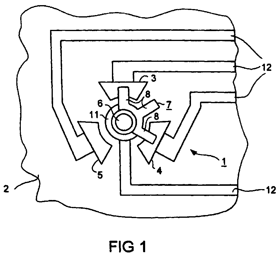
- the coding switch have six switch positions, so three with a fixed contact points arranged at a 120 ° pitch intended.
- the sliding contacts of the rotatable switching element are accordingly in half the pitch, i.e. H. under each 60 ° arranged.
- the total number of connecting lines is 12 four.
- Coding switch according to the invention for higher numbers of Switch positions differ only in the number the fixed contact points and the angle at which the sliding contacts of the rotatable switching element are arranged are. Accordingly, a coding switch according to the invention with eight switch positions evenly over the circumference distributed four fixed contact points while a coding switch with ten positions five fixed contact points having.
- the invention is in a variety of electronic devices can be used with advantage, where a setting by a User.
- a setting by a User Form a preferred application electronic overcurrent releases for low-voltage circuit breakers.
- the substrate as a circuit board for the printed circuit of the electronic Overcurrent release be formed during the rotatable switching element by an adjusting element for the value of a Trigger parameter is actuated.
- circuit board of an electronic device at the same time as a carrier of the contact points and conductor tracks one Coding switch and as a pivot bearing of a rotatable contact member is known per se and is e.g. in EP 0 050 861 described.
- a contact scheme for the coding switch corresponding to FIG. 5 4 shows FIG. 6.
- the coding switch 1 shown in Figure 1 has a Fixed substrate 2 arranged in uniform division Contact points 3, 4 and 5. At the center of the circular The arrangement of the contact points 3, 4 and 5 is the substrate 2 provided with a through opening 6, which for receiving a pin-like setting member 7 for a rotatable switching member 10 serves ( Figure 2). Concentric to the through opening 6 is an annular one on the substrate 2 Supply contact point 11 with which the switching element 10 constantly is engaged. Furthermore, the switching element 10 has three Sliding contacts 11 on that in half the division of the fixed Contact points 3, 4 and 5 are arranged, d. H. in the present Fall below 60 ° because the division of the fixed contact points Is 120 °.
- Each of the contact points 3, 4 and 5 and the lead contact point 11 are connected in a known manner by a conductor track 12 to an evaluation circuit which checks and evaluates connections defined by the respective position of the switching element 7.
- 5 shows the contact scheme in the form of a table. The six different switching positions of the rotatable switching element 7 are in this table in the left column Position 0 to 5 ". The following columns indicate the contact at the individual contact points 3, 4 and 5, which are illustrated by a reduced representation with the respective highlighting of the respective contact point. In the columns relating to the individual contact points are with 1 "the existing and with 0 "denotes the non-existent contact with the switching element 7.
- a coding switch is a further exemplary embodiment in FIG shown for eight positions.
- the coding switch 13 has four fixed contact points 14, 15, 16 and 17, which cooperate with a rotatable switching element 18.
- the Switching element 18 in turn has three sliding contacts 20 which in the half division of the contact points 14, 15, 16 and 17, d. H. are arranged at an angle of 45 °.
- Conductor tracks 12 on the substrate 2 serve in the same way as already explained on the examination and removal of the respective Switch position.
- a coding switch is a further exemplary embodiment in FIG 21 illustrates for ten switch positions.
- the coding switch 21 therefore five fixed contact points 22, 23, 24, 25 and 26 in Connection to a rotatable switching element 27.
- the three Sliding contacts of the switching element 27 are in turn in the half division of the fixed contact points, in this case arranged at an angle of 36 °.
- the contact scheme of the coding switch 21 according to FIG. 4 is shown in FIG. 6.
- the structure of this corresponds to the table according to FIG. 5, with the switch positions with Positions 0 to 9 "and additionally with a symbolic representation for the position of the rotatable switching element 27.
- the respective affected fixed contact points are illustrated in FIG. 5 as a reduced representation of the arrangement of the fixed contact points with emphasis on the affected contact point. How to recognizes, there is a clear combination of contact assignments of the fixed contact points 22 - 26 by the rotatable switching element 27 for each switching position, which can therefore be evaluated by a logic circuit.
- Coding switches according to the invention are suitable, as already mentioned in the introduction, for use in numerous electronic Devices where it matters that a user can select predetermined fixed setting values, for example a temperature, a current or a voltage.
- the coding switches explained have proven to be suitable for use in electronic overcurrent releases for low-voltage circuit breakers.
- the substrate 2 serves as the substrate 2 a circuit board on which the printed circuit of the overcurrent release.
- the coding switches have the task here is to set the values of certain parameters, e.g. B. the amount of current at which a trip to be held. It may also be desirable to determine Assign a delay time to triggering operations, or one earth leakage current leading to tripping.
- the adjuster 7, according to the figure 2 in the through opening 7 of the substrate 2 can be engaged, forms itself the control element to be handled by the user or with one connected by means of a simple coupling his.
- the fixed contact points and the supply contact point are also part of the applications mentioned the printed circuit. To make contact as safe as possible to ensure that the fixed contact points, the lead contact point and the rotatable switching element be gilded.
Landscapes
- Rotary Switch, Piano Key Switch, And Lever Switch (AREA)
Abstract
Ein Kodierschalter (1) weist auf einem ebenen Substrat (2)
kreisförmig angeordnete ortsfeste Kontaktstellen (3, 4, 5) in
gleichmäßiger Teilung auf. Ein drehbares Schaltglied (7) besitzt
im halben Teilungsmaß der ortsfesten Kontaktstellen (3,
4, 5) angeordnete und miteinander verbundene Schleifkontakte
(8) auf. Je nach der Stellung des drehbaren Schaltgliedes (7)
stehen ein Schleifkontakt (8) oder zwei Schleifkontakte (8)
mit einer bzw. zwei der ortsfesten Kontaktstellen (3, 4, 5)
in Eingriff. Das die Kontaktstellen (3, 4, 5) tragende Substrat
(2) kann die Leiterplatte eines elektronischen Gerätes
sein und kann eine Öffnung zur Lagerung eines Einstellgliedes
(10) für das bewegbare Schaltglied (7) besitzen.
Description
Die Erfindung betrifft einen Kodierschalter mit auf einem ebenen Substrat kreisförmig angeordneten Kontaktstellen und mit einem drehbaren, mit den ortsfesten Kontaktstellen zusammenwirkenden Schaltglied, das ständig im Eingriff mit einer auf dem Substrat angeordneten Zuleitungskontaktstelle steht.The invention relates to a coding switch on a flat substrate circularly arranged contact points and with a rotatable, interacting with the fixed contact points Switching element that is constantly engaged with a stands on the substrate arranged lead contact point.
Ein Kodierschalter der vorstehend genannten Art ist durch die
EP 0 050 804 A2 bekannt geworden. Die ortsfesten Kontaktstellen
sind bei diesem Kodierschalter auf mehreren konzentrischen
Kreisbahnen angeordnet, wobei das drehbare Schaltglied
für jede der Kreisbahnen mit einem Schleifkontakt versehen
ist. Der Erfindung liegt ausgehend hiervon die Aufgabe zugrunde,
die Anzahl der Kontaktstellen für eine gegebene Anzahl
von zu kodierenden Schaltstellungen möglichst gering zu
machen und damit den Kodierschalter zu vereinfachen und betriebssicherer
zu gestalten.A coding switch of the type mentioned above is by the
Diese Aufgabe wird gemäß der Erfindung dadurch gelöst, daß die ortsfesten Kontaktstellen in gleichmäßiger Teilung auf einer einzigen, zur Drehachse des drehbaren Schaltgliedes konzentrischen Kreisbahn angeordnet sind und daß das drehbare Schaltglied im halben Teilungsmaß der ortsfesten Kontaktstellen angeordnete und miteinander verbundene Schleifkontakte aufweist, wobei die Abstände der ortsfesten Kontaktstellen entlang der Kreisbahn und die Breite der Schleifkontakte so bemessen sind, daß je nach Stellung des Schaltgliedes ein Schleifkontakt oder zwei Schleifkontakte mit einer bzw. zwei der ortsfesten Kontaktstellen in Eingriff steht bzw. stehen.This object is achieved according to the invention in that the fixed contact points in an even division a single, to the axis of rotation of the rotatable switching element concentric circular path are arranged and that the rotatable Switching element in half the pitch of the fixed contact points arranged and interconnected sliding contacts has, the distances between the fixed contact points along the circular path and the width of the sliding contacts so are dimensioned that depending on the position of the switching element Sliding contact or two sliding contacts with one or two the stationary contact points are engaged.
Wesentlich für die Erfindung ist ein einheitliches Bauprinzip für Kodierschalter mit einer unterschiedlichen Anzahl zu kodierender Schaltstellungen. Dabei ist stets die Anzahl der abzufragenden Leitungen halb so groß wie die Anzahl der Schaltstellungen, zuzüglich jeweils einer Anschlußleitung für die Zuleitungskontaktstelle. Soll beispielsweise der Kodierschalter sechs Schaltstellungen besitzen, so werden drei mit einer Teilung von 120° angeordnete ortsfeste Kontaktstellen vorgesehen. Die Schleifkontakte des drehbaren Schaltgliedes sind demnach in dem halben Teilungsmaß, d. h. unter jeweils 60° angeordnet. Die Gesamtzahl der Anschlußleitungen 12 beträgt vier.A uniform construction principle is essential for the invention for coding switches with different numbers to be coded Switch positions. It is always the number of lines to be queried half the number of Switch positions, plus one connecting line for each the supply contact point. For example, the coding switch have six switch positions, so three with a fixed contact points arranged at a 120 ° pitch intended. The sliding contacts of the rotatable switching element are accordingly in half the pitch, i.e. H. under each 60 ° arranged. The total number of connecting lines is 12 four.
Kodierschalter nach der Erfindung für höhere Anzahlen von Schaltstellungen unterscheiden sich somit nur durch die Anzahl der ortsfesten Kontaktstellen und des Winkels, unter dem die Schleifkontakte des drehbaren Schaltgliedes angeordnet sind. Demnach besitzt ein Kodierschalter nach der Erfindung mit acht Schaltstellungen über den Kreisumfang gleichmäßig verteilte vier ortsfeste Kontaktstellen, während ein Kodierschalter mit zehn Stellungen fünf ortsfeste Kontaktstellen aufweist.Coding switch according to the invention for higher numbers of Switch positions differ only in the number the fixed contact points and the angle at which the sliding contacts of the rotatable switching element are arranged are. Accordingly, a coding switch according to the invention with eight switch positions evenly over the circumference distributed four fixed contact points while a coding switch with ten positions five fixed contact points having.
Die Erfindung ist bei einer Vielzahl elektronischer Geräte mit Vorteil einsetzbar, bei denen eine Einstellung durch einen Benutzer vorzunehmen ist. Eine bevorzugte Anwendung bilden hierbei elektronische Überstromauslöser für Niederspannungs-Leistungsschalter. Bei dieser Anwendung kann das Substrat als Leiterplatte für die gedruckte Schaltung des elektronischen Überstromauslösers ausgebildet sein, während das drehbare Schaltglied durch ein Einstellorgan für den Wert eines Auslöseparameters betätigbar ist.The invention is in a variety of electronic devices can be used with advantage, where a setting by a User. Form a preferred application electronic overcurrent releases for low-voltage circuit breakers. In this application, the substrate as a circuit board for the printed circuit of the electronic Overcurrent release be formed during the rotatable switching element by an adjusting element for the value of a Trigger parameter is actuated.
Die Benutzung der Leiterplatte eines elektronischen Gerätes
zugleich als Träger der Kontaktstellen und Leiterbahnen eines
Kodierschalters sowie als Drehlager eines drehbaren Kontaktgliedes
ist an sich bekannt und ist z.B. in der EP 0 050 861
beschrieben.The use of the circuit board of an electronic device
at the same time as a carrier of the contact points and conductor tracks one
Coding switch and as a pivot bearing of a rotatable contact member
is known per se and is e.g. in
Die Erfindung wird im folgenden anhand der in den Figuren
dargestellten Ausführungsbeispiele näher erläutert.
Ein der Figur 5 entsprechendes Kontaktschema für den Kodierschalter gemäß der Figur 4 zeigt die Figur 6.A contact scheme for the coding switch corresponding to FIG. 5 4 shows FIG. 6.
Der in der Figur 1 gezeigte Kodierschalter 1 weist auf einem
Substrat 2 in gleichmäßiger Teilung angeordnete ortsfeste
Kontaktstellen 3, 4 und 5 auf. Im Zentrum der kreisförmigen
Anordnung der Kontaktstellen 3, 4 und 5 ist das Substrat 2
mit einer Durchgangsöffnung 6 versehen, die zur Aufnahme eines
zapfenartigen Einstellorgans 7 für ein drehbares Schaltglied
10 dient (Figur 2). Konzentrisch zu der Durchgangsöffnung
6 befindet sich auf dem Substrat 2 eine kreisringförmige
Zuleitungskontaktstelle 11, mit der das Schaltglied 10 ständig
in Eingriff steht. Ferner weist das Schaltglied 10 drei
Schleifkontakte 11 auf, die in der halben Teilung der ortsfesten
Kontaktstellen 3, 4 und 5 angeordnet sind, d. h. im vorliegenden
Fall unter 60°, da die Teilung der ortsfesten Kontaktstellen
120° beträgt.The
Jede der Kontaktstellen 3, 4 und 5 sowie die Zuleitungskontaktstelle
11 sind durch eine Leiterbahn 12 in bekannter Weise
mit einer Auswertungsschaltung verbunden, die durch die
jeweilige Stellung des Schaltgliedes 7 definierte Verbindungen
prüft und auswertet. In der Figur 5 ist hierzu in Gestalt
einer Tabelle das Kontaktschema dargestellt. Die sechs unterschiedlichen
Schaltstellungen des drehbaren Schaltgliedes 7
sind in dieser Tabelle in der linken Spalte mit 
Als weiteres Ausführungsbeispiel ist in der Figur 3 ein Kodierschalter
für acht Stellungen gezeigt. Der Kodierschalter
13 weist vier ortsfeste Kontaktstellen 14, 15, 16 und 17 auf,
die mit einem drehbaren Schaltglied 18 zusammenwirken. Das
Schaltglied 18 besitzt wiederum drei Schleifkontakte 20, die
in der halben Teilung der Kontaktstellen 14, 15, 16 und 17,
d. h. unter einem Winkel von 45° angeordnet sind. Leiterbahnen
12 auf dem Substrat 2 dienen in der gleichen Weise wie
bereits erläutert zur Prüfung und Abtrage der jeweiligen
Schaltstellung.A coding switch is a further exemplary embodiment in FIG
shown for eight positions. The
In der Figur 4 ist als weiteres Ausführungsbeispiel ein Kodierschalter
21 für zehn Schaltstellungen veranschaulicht.
Nach dem Prinzip der Erfindung weist der Kodierschalter 21
daher fünf ortsfeste Kontaktstellen 22, 23, 24, 25 und 26 in
Verbindung mit einem drehbaren Schaltglied 27 auf. Die drei
Schleifkontakte des Schaltgliedes 27 sind wiederum in der
halben Teilung der ortsfesten Kontaktstellen, in diesem Fall
unter einem Winkel von 36°, angeordnet. Auf dem Substrat befinden
sich insgesamt sechs Leiterbahnen 12, von denen fünf
mit den ortsfesten Kontaktstellen 22-26 und die verbleibende
Leiterbahn mit der Zuleitungskontaktstelle 11 verbunden sind.A coding switch is a further exemplary embodiment in FIG
21 illustrates for ten switch positions.
According to the principle of the invention, the coding switch 21
therefore five
Das Kontaktschema des Kodierschalters 21 gemäß der Figur 4
zeigt die Figur 6. Diese entspricht in ihrem Aufbau der Tabelle
gemäß der Figur 5, wobei die Schaltstellungen mit
Kodierschalter nach der Erfindung eignen sich, wie bereits
einleitend erwähnt, zur Anwendung in zahlreichen elektronischen
Geräten, bei denen es darauf ankommt, daß ein Benutzer
vorgegebene feste Einstellwerte auswählen kann, beispielsweise
eine Temperatur, ein Strom oder eine Spannung. Als besonders
geeignet erweisen sich die erläuterten Kodierschalter
zur Anwendung in elektronischen Überstromauslösern für Niederspannungs-Leistungsschalter.
In diesem Fall dient als Substrat
2 eine Leiterplatte, auf der sich die gedruckte Schaltung
des Überstromauslösers befindet. Die Kodierschalter haben
hier die Aufgabe, die Werte bestimmter Parameter festzulegen,
z. B. die Höhe des Stromes, bei der eine Auslösung
stattfinden soll. Ebenso kann es erwünscht sein, bestimmten
Auslösevorgängen eine Verzögerungszeit zuzuweisen, oder einen
zur Auslösung führenden Erdschlußstrom einzustellen. Das Einstellorgan
7, das gemäß der Figur 2 in die Durchgangsöffnung
7 des Substrates 2 eingerastet sein kann, bildet dabei selbst
das vom Benutzer zu handhabende Bedienungsorgan oder kann mit
einem solchen mittels einer einfachen Kupplung verbunden
sein.Coding switches according to the invention are suitable, as already
mentioned in the introduction, for use in numerous electronic
Devices where it matters that a user
can select predetermined fixed setting values, for example
a temperature, a current or a voltage. As special
the coding switches explained have proven to be suitable
for use in electronic overcurrent releases for low-voltage circuit breakers.
In this case it serves as the substrate
2 a circuit board on which the printed circuit
of the overcurrent release. The coding switches have
the task here is to set the values of certain parameters,
e.g. B. the amount of current at which a trip
to be held. It may also be desirable to determine
Assign a delay time to triggering operations, or one
earth leakage current leading to tripping. The
Die ortsfesten Kontaktstellen und die Zuleitungskontaktstelle sind bei den erwähnten Anwendungsfällen gleichfalls Bestandteil der gedruckten Schaltung. Um eine möglichst sichere Kontaktgabe zu gewährleiten, können die ortsfesten Kontaktstellen, die Zuleitungskontaktstelle und das drehbare Schaltglied vergoldet sein.The fixed contact points and the supply contact point are also part of the applications mentioned the printed circuit. To make contact as safe as possible to ensure that the fixed contact points, the lead contact point and the rotatable switching element be gilded.
Claims (2)
dadurch gekennzeichnet,
daß die ortsfesten Kontaktstellen (3, 4, 5; 14, 15, 16, 17; 22, 23, 24, 25, 26) in gleichmäßiger Teilung auf einer einzigen, zur Drehachse des drehbaren Schaltgliedes (7; 18; 27) konzentrischen Kreisbahn angeordnet sind und daß das drehbare Schaltglied (7; 18; 27) drei im halben Teilungsmaß der ortsfesten Kontaktstellen (3, 4, 5; 14, 15, 16, 17; 22, 23, 24, 25, 26) angeordnete und miteinander verbundene Schleifkontakte (10; 20; 28) aufweist, wobei die Abstände der ortsfesten Kontaktstellen (3, 4, 5; 14, 15, 16, 17; 22, 23, 24, 25, 26) entlang der Kreisbahn und die Breite der Schleifkontakte (10; 20; 28) so bemessen sind, daß je nach Stellung des Schaltgliedes ein Schleifkontakt oder zwei Schleifkontakte mit einer bzw. mit zwei der ortsfesten Kontaktstellen (3, 4, 5; 14, 15, 16, 17; 22, 23, 24, 25, 26) in Eingriff steht bzw. stehen.Coding switch (1, 13, 21) with contact points (3, 4, 5; 14, 15, 16, 17; 22, 23, 24, 25, 26) arranged in a circle on a flat substrate (2) and with a rotatable, with the stationary contact points interacting switching element (7; 18; 27) which is constantly in engagement with a feed contact point (11) arranged on the substrate (2),
characterized,
that the fixed contact points (3, 4, 5; 14, 15, 16, 17; 22, 23, 24, 25, 26) in uniform division on a single circular path concentric to the axis of rotation of the rotatable switching element (7; 18; 27) are arranged and that the rotatable switching member (7; 18; 27) three half-pitch of the fixed contact points (3, 4, 5; 14, 15, 16, 17; 22, 23, 24, 25, 26) arranged and interconnected Has sliding contacts (10; 20; 28), the distances between the fixed contact points (3, 4, 5; 14, 15, 16, 17; 22, 23, 24, 25, 26) along the circular path and the width of the sliding contacts ( 10; 20; 28) are dimensioned so that, depending on the position of the switching element, one sliding contact or two sliding contacts with one or with two of the fixed contact points (3, 4, 5; 14, 15, 16, 17; 22, 23, 24 , 25, 26) is or are engaged.
dadurch gekennzeichnet, daß
das Substrat (2) als Leiterplatte für die gedruckte Schaltung eines elektronischen Auslösers eines Niederspannungs-Leistungsschalters ausgebildet ist und das drehbare Schaltglied (7; 17; 28) durch ein Einstellorgan (10) für den Wert eines Auslöseparameters betätigbar ist.Coding switch according to claim 1,
characterized in that
the substrate (2) is designed as a printed circuit board for the printed circuit of an electronic release of a low-voltage circuit breaker and the rotatable switching element (7; 17; 28) can be actuated by an adjusting element (10) for the value of a release parameter.
Applications Claiming Priority (2)
| Application Number | Priority Date | Filing Date | Title |
|---|---|---|---|
| DE19910149 | 1999-02-26 | ||
| DE1999110149 DE19910149A1 (en) | 1999-02-26 | 1999-02-26 | Coding switch with a rotatable switching element |
Publications (2)
| Publication Number | Publication Date |
|---|---|
| EP1032007A2 true EP1032007A2 (en) | 2000-08-30 |
| EP1032007A3 EP1032007A3 (en) | 2001-05-23 |
Family
ID=7900121
Family Applications (1)
| Application Number | Title | Priority Date | Filing Date |
|---|---|---|---|
| EP00250069A Withdrawn EP1032007A3 (en) | 1999-02-26 | 2000-02-25 | Encoding switch with a rotatable switch member |
Country Status (2)
| Country | Link |
|---|---|
| EP (1) | EP1032007A3 (en) |
| DE (1) | DE19910149A1 (en) |
Cited By (1)
| Publication number | Priority date | Publication date | Assignee | Title |
|---|---|---|---|---|
| CN109545603A (en) * | 2019-01-05 | 2019-03-29 | 叶永胜 | A kind of waterproof rotary switch of terminal buckle-type |
Families Citing this family (1)
| Publication number | Priority date | Publication date | Assignee | Title |
|---|---|---|---|---|
| DE10319191A1 (en) * | 2003-04-29 | 2004-11-25 | Robert Bosch Gmbh | Sliding contact arrangement for a D-switch module, in particular for an electronic motor vehicle ignition starter lock |
Family Cites Families (4)
| Publication number | Priority date | Publication date | Assignee | Title |
|---|---|---|---|---|
| DE3040546C2 (en) * | 1980-10-28 | 1983-04-07 | Siemens AG, 1000 Berlin und 8000 München | Coding switch |
| DE3040545C2 (en) * | 1980-10-28 | 1983-09-22 | Siemens AG, 1000 Berlin und 8000 München | Coding switch |
| GB2217914B (en) * | 1988-04-23 | 1992-02-19 | Proizv Ob Mi Chasovoi Z | Switching device for electronic watch |
| CH688950B5 (en) * | 1995-08-22 | 1998-12-31 | Ebauchesfabrik Eta Ag | Synchronization device of an analog display with an electronic counter in a timepiece. |
-
1999
- 1999-02-26 DE DE1999110149 patent/DE19910149A1/en not_active Withdrawn
-
2000
- 2000-02-25 EP EP00250069A patent/EP1032007A3/en not_active Withdrawn
Cited By (1)
| Publication number | Priority date | Publication date | Assignee | Title |
|---|---|---|---|---|
| CN109545603A (en) * | 2019-01-05 | 2019-03-29 | 叶永胜 | A kind of waterproof rotary switch of terminal buckle-type |
Also Published As
| Publication number | Publication date |
|---|---|
| DE19910149A1 (en) | 2000-08-31 |
| EP1032007A3 (en) | 2001-05-23 |
Similar Documents
| Publication | Publication Date | Title |
|---|---|---|
| DE10084599B4 (en) | Electromagnetic switching device | |
| DE4140587C2 (en) | Electronic control device for switching multiple electrical loads | |
| DE2555137A1 (en) | BUTTON SWITCHES | |
| DE2655814C2 (en) | Coding switch | |
| EP0960426A1 (en) | Position signalling device | |
| EP0847587A1 (en) | Power circuit-breaker with current transformers and data store | |
| EP1032007A2 (en) | Encoding switch with a rotatable switch member | |
| EP0196622A2 (en) | Rotary and slide potentiometer (tap changer switch) | |
| DE3405688C2 (en) | ||
| DE2440550C3 (en) | Switch for auxiliary circuits | |
| DE69413163T2 (en) | Four-pole differential circuit breaker | |
| DE2937948C2 (en) | ||
| DE2462035C3 (en) | keyboard | |
| DE2830661C2 (en) | Switching device for electrical devices | |
| EP0978131A1 (en) | Circuit arrangement for a load transfer switch | |
| EP0474085B1 (en) | Multimeter for measuring different quantities at will | |
| DE19642205C2 (en) | Electrical switching device that can be used as a keus switch | |
| DE3632383A1 (en) | ELECTRICAL SWITCHING DEVICE FOR CIRCUITS IN MOTOR VEHICLES | |
| DE2452944A1 (en) | BUTTON SWITCH SYSTEM | |
| DE3505033A1 (en) | KEY SWITCH | |
| DE1540371A1 (en) | Electric circuit breaker for high rated currents | |
| DE2611021A1 (en) | Change-over switch for printed circuits - has torsion spring extensions forming moving contacts and pins for coacting with conductor tracks | |
| DE2061871C3 (en) | Device for controlling a step movement as a function of a sequence of electrical signals | |
| AT244091B (en) | Counter with electromagnetically advanced digit roller | |
| DE2542958A1 (en) | Signalling contact system for motor driven tap changers - uses snap action switches for control or display of individual switching stages |
Legal Events
| Date | Code | Title | Description |
|---|---|---|---|
| PUAI | Public reference made under article 153(3) epc to a published international application that has entered the european phase |
Free format text: ORIGINAL CODE: 0009012 |
|
| AK | Designated contracting states |
Kind code of ref document: A2 Designated state(s): DE FR GB IT |
|
| AX | Request for extension of the european patent |
Free format text: AL;LT;LV;MK;RO;SI |
|
| PUAL | Search report despatched |
Free format text: ORIGINAL CODE: 0009013 |
|
| AK | Designated contracting states |
Kind code of ref document: A3 Designated state(s): AT BE CH CY DE DK ES FI FR GB GR IE IT LI LU MC NL PT SE |
|
| AX | Request for extension of the european patent |
Free format text: AL;LT;LV;MK;RO;SI |
|
| 17P | Request for examination filed |
Effective date: 20010620 |
|
| AKX | Designation fees paid |
Free format text: DE FR GB IT |
|
| STAA | Information on the status of an ep patent application or granted ep patent |
Free format text: STATUS: THE APPLICATION IS DEEMED TO BE WITHDRAWN |
|
| 18D | Application deemed to be withdrawn |
Effective date: 20050901 |