EP1032019A2 - Cathode-ray tube - Google Patents
Cathode-ray tube Download PDFInfo
- Publication number
- EP1032019A2 EP1032019A2 EP00103787A EP00103787A EP1032019A2 EP 1032019 A2 EP1032019 A2 EP 1032019A2 EP 00103787 A EP00103787 A EP 00103787A EP 00103787 A EP00103787 A EP 00103787A EP 1032019 A2 EP1032019 A2 EP 1032019A2
- Authority
- EP
- European Patent Office
- Prior art keywords
- ground electrode
- glass panel
- electric field
- film
- conductive film
- Prior art date
- Legal status (The legal status is an assumption and is not a legal conclusion. Google has not performed a legal analysis and makes no representation as to the accuracy of the status listed.)
- Withdrawn
Links
- 239000011521 glass Substances 0.000 claims abstract description 50
- 238000004381 surface treatment Methods 0.000 claims abstract description 18
- 229910000679 solder Inorganic materials 0.000 claims description 10
- 230000005684 electric field Effects 0.000 abstract description 36
- 230000000694 effects Effects 0.000 abstract description 10
- WOCIAKWEIIZHES-UHFFFAOYSA-N ruthenium(iv) oxide Chemical compound O=[Ru]=O WOCIAKWEIIZHES-UHFFFAOYSA-N 0.000 description 5
- XEEYBQQBJWHFJM-UHFFFAOYSA-N Iron Chemical compound [Fe] XEEYBQQBJWHFJM-UHFFFAOYSA-N 0.000 description 4
- 239000000463 material Substances 0.000 description 4
- KDLHZDBZIXYQEI-UHFFFAOYSA-N Palladium Chemical compound [Pd] KDLHZDBZIXYQEI-UHFFFAOYSA-N 0.000 description 3
- 230000002093 peripheral effect Effects 0.000 description 3
- 229910001925 ruthenium oxide Inorganic materials 0.000 description 3
- 238000005476 soldering Methods 0.000 description 3
- XOLBLPGZBRYERU-UHFFFAOYSA-N tin dioxide Chemical compound O=[Sn]=O XOLBLPGZBRYERU-UHFFFAOYSA-N 0.000 description 3
- VYPSYNLAJGMNEJ-UHFFFAOYSA-N Silicium dioxide Chemical compound O=[Si]=O VYPSYNLAJGMNEJ-UHFFFAOYSA-N 0.000 description 2
- BQCADISMDOOEFD-UHFFFAOYSA-N Silver Chemical compound [Ag] BQCADISMDOOEFD-UHFFFAOYSA-N 0.000 description 2
- 239000011248 coating agent Substances 0.000 description 2
- 238000000576 coating method Methods 0.000 description 2
- 229910052742 iron Inorganic materials 0.000 description 2
- 238000004519 manufacturing process Methods 0.000 description 2
- 238000000034 method Methods 0.000 description 2
- BASFCYQUMIYNBI-UHFFFAOYSA-N platinum Chemical compound [Pt] BASFCYQUMIYNBI-UHFFFAOYSA-N 0.000 description 2
- 229910052709 silver Inorganic materials 0.000 description 2
- 239000004332 silver Substances 0.000 description 2
- 239000000758 substrate Substances 0.000 description 2
- 230000002411 adverse Effects 0.000 description 1
- 229910052681 coesite Inorganic materials 0.000 description 1
- 239000004020 conductor Substances 0.000 description 1
- -1 containing ITO Substances 0.000 description 1
- 229910052906 cristobalite Inorganic materials 0.000 description 1
- 230000005672 electromagnetic field Effects 0.000 description 1
- 238000010894 electron beam technology Methods 0.000 description 1
- 239000012212 insulator Substances 0.000 description 1
- 230000007257 malfunction Effects 0.000 description 1
- 238000005259 measurement Methods 0.000 description 1
- 239000000203 mixture Substances 0.000 description 1
- 229910052763 palladium Inorganic materials 0.000 description 1
- 239000012466 permeate Substances 0.000 description 1
- 229910052697 platinum Inorganic materials 0.000 description 1
- 230000003014 reinforcing effect Effects 0.000 description 1
- 230000000630 rising effect Effects 0.000 description 1
- 230000035939 shock Effects 0.000 description 1
- 239000000377 silicon dioxide Substances 0.000 description 1
- 238000004528 spin coating Methods 0.000 description 1
- 238000004544 sputter deposition Methods 0.000 description 1
- 229910052682 stishovite Inorganic materials 0.000 description 1
- 230000001629 suppression Effects 0.000 description 1
- 229910001887 tin oxide Inorganic materials 0.000 description 1
- 229910052905 tridymite Inorganic materials 0.000 description 1
- 229910052721 tungsten Inorganic materials 0.000 description 1
Images


Classifications
-
- H—ELECTRICITY
- H01—ELECTRIC ELEMENTS
- H01J—ELECTRIC DISCHARGE TUBES OR DISCHARGE LAMPS
- H01J29/00—Details of cathode-ray tubes or of electron-beam tubes of the types covered by group H01J31/00
- H01J29/86—Vessels; Containers; Vacuum locks
-
- H—ELECTRICITY
- H01—ELECTRIC ELEMENTS
- H01J—ELECTRIC DISCHARGE TUBES OR DISCHARGE LAMPS
- H01J29/00—Details of cathode-ray tubes or of electron-beam tubes of the types covered by group H01J31/00
- H01J29/86—Vessels; Containers; Vacuum locks
- H01J29/867—Means associated with the outside of the vessel for shielding, e.g. magnetic shields
- H01J29/868—Screens covering the input or output face of the vessel, e.g. transparent anti-static coatings, X-ray absorbing layers
-
- H—ELECTRICITY
- H01—ELECTRIC ELEMENTS
- H01J—ELECTRIC DISCHARGE TUBES OR DISCHARGE LAMPS
- H01J2229/00—Details of cathode ray tubes or electron beam tubes
- H01J2229/0007—Elimination of unwanted or stray electromagnetic effects
- H01J2229/0015—Preventing or cancelling fields leaving the enclosure
- H01J2229/0023—Passive means
-
- H—ELECTRICITY
- H01—ELECTRIC ELEMENTS
- H01J—ELECTRIC DISCHARGE TUBES OR DISCHARGE LAMPS
- H01J2229/00—Details of cathode ray tubes or electron beam tubes
- H01J2229/863—Passive shielding means associated with the vessel
- H01J2229/8631—Coatings
Definitions
- the present invention relates to a cathode-ray tube.
- the present invention relates to a structure of a ground electrode for reducing an undesired electromagnetic field generated particularly on a front surface of a glass panel.
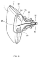
- FIG. 6 is a partially cut-away perspective view of a general cathode-ray tube (hereinafter, referred to as a "CRT") apparatus composed of a CRT and a deflection yoke.
- the CRT includes a glass panel 1, a glass covering composed of a funnel part 91 and a neck part 92, an electron gun 93 sealed in the neck part 92, a fluorescent screen surface 96 formed on an inner surface of the glass panel 1, color selection electrodes 97 disposed on the electron gun 93 side of the fluorescent screen surface 96 so as to maintain a predetermined interval, a magnetic shield 98, and a multi-layer film (not shown) having antistatic and antireflection functions, formed on an outer surface of the glass panel 1.
- the deflection yoke 95 is attached to the periphery of the neck part 92 of the CRT so as to deflect an electron beam 94 radiated from the electron gun 93.
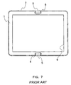
- Figure 7 is a plan view of the glass panel 1, and Figure 3 is an enlarged cross-sectional view of a peripheral portion of the glass panel 1.
- a surface treatment film 8 composed of a conductive film 3 and a multi-layer film 2 of insulating layers 4 having an antireflection function and the like is formed on the surface of the glass panel 1.
- a ground electrode 6 is provided on the surface treatment film 8 so as to be electrically connected with the conductive film 3 through ultrasonic solder (Japanese Laid-Open Publication No. 8-287850). As shown in Figure 7, in general, a pair of ground electrodes 6 are provided on upper and lower portions of the glass panel 1 outside an effective screen region 9.
- the fluorescent screen surface 96 is held at a potential of an anode supplied with a high voltage. Therefore, the glass panel 1 is charged to a high potential, which may have adverse effects such as giving shock to a user and causing electronic equipment in the vicinity to malfunction due to discharge.
- the conductive film 3 and the ground electrode 6 are provided for the purpose of avoiding such a situation.
- a leakage electric field is required to be 1.0 V/m or less with respect to an alternating electric field in a VLF (Very Low Frequency) band (i.e., 2 kHz to 400 kHz) at a position 30 cm away from the front surface of a glass panel.
- VLF Very Low Frequency
- Japanese Laid-Open Publication No. 10-3868 discloses that a transparent conductive film with a high refractive index having a surface resistance of 9 ⁇ 10 2 ⁇ / ⁇ or less is formed on the outer surface of a glass panel, and a plurality of terminals electrically connected with the conductive film are disposed on two or four sides of the glass panel. Furthermore, Japanese Laid-Open Publication No.
- a conductive film with a surface resistance of 1 ⁇ 10 3 ⁇ / ⁇ or less and an antireflection film (hereinafter, referred to as an "AR film”) are formed on a transparent substrate, the resultant substrate is attached to the outer surface of a glass panel, and an electrode is provided on the outermost layer so as to be grounded in an electrical circuit manner.
- an electric potential induced on the glass panel is allowed to dissipate to a ground surface on the circuit through the electrode on the outermost surface of the glass panel, whereby it is attempted to prevent the surface of the glass panel from reaching a high potential.
- the resistance of the conductive film formed as a lower layer of the AR film on the glass panel is required to be about 1 ⁇ 10 3 ⁇ / ⁇ or less.
- a special material containing silver and platinum must be coated by spin coating or sputtering. This increases the production cost.
- a cathode-ray tube of the present invention has a structure in which a surface treatment film including an antireflection film layered on a conductive film with a surface resistance of 1 ⁇ 10 3 ⁇ / ⁇ or more is provided on a surface of a glass panel, and a ground electrode electrically connected with the conductive film and grounded is formed on the surface treatment film, wherein a surface area of the ground electrode is 500 mm 2 or more.
- a surface area of the ground electrode i.e., a contact area between the ground electrode and the conductive film
- a leakage electric field can be suppressed to 1.0 V/m or less with respect to an alternating electric field in a VLF band.
- the ground electrode is provided in a band shape so as to be substantially parallel to an outer edge of the glass panel outside an effective screen of the glass panel, and the ground electrode has a length of 100 mm or more and a width of 5 mm or more. Because of this, a space of the glass panel outside the effective screen can be efficiently used.
- the ground electrode is provided on a side where at least an anode terminal is provided among outer edges of the glass panel.
- the anode terminal is supplied with the highest voltage and is one of the main sources for causing a leakage electric field. Therefore, by providing the ground electrode in the vicinity of the anode terminal, a leakage electric field can be efficiently suppressed.
- the ground electrode is formed by ultrasonic solder. If ultrasonic solder is used, the ground electrode can be formed directly on the surface treatment film without peeling off the surface treatment film.
- the CRT of the present invention is characterized by the size, attachment position, and number of ground electrodes provided on a glass panel.
- FIG. 1 is a plan view of a glass panel according to the present invention.
- a surface treatment film (not shown) composed of an AR film and a conductive film with a surface resistance of 1 ⁇ 10 3 ⁇ / ⁇ or more is provided on the surface of a glass panel 1.
- a ground electrode 6 is formed on the surface treatment film, using ultrasonic solder or the like, as a conductive film so as to be electrically connected with the conductive film.
- the ground electrode 6 is electrically connected with a reinforcing band 7 through a conductive tape 5.
- the cross-section of a peripheral portion of the glass panel 1 has the same structure as that of the prior art as shown in Figure 3.
- the surface treatment film 8 is composed of a conductive film 3 (lowermost layer) and a double-layer insulating film (AR film) 4 made of insulator layered on the conductive film 3.
- the surface treatment film 8 may be formed by direct coating onto the glass panel 1 or by attachment of an AR panel to the glass panel 1.
- the conductive film 3 mainly contains ruthenium oxide (Ru 2 O) with a surface resistance of 5 ⁇ 10 3 ⁇ / ⁇ , and has a thickness of about 0.1 ⁇ m.
- the conductive film 3 may be made of a material mainly containing tin oxide (SnO 2 ), a material mainly containing ITO, or a material mainly containing a mixture of silver (Ag) and palladium (Pd).
- the insulating film 4 includes the first layer of RuO 2 (thickness: 180 nm; refractive index: 1.75) and the second layer of SiO 2 (thickness: 150 nm; refractive index: 1.47).
- the ground electrode 6 has a width W of 5 mm and a length L of 100 mm, as shown in Figure 2.
- the ground electrode 6 is provided at one middle position on the side of an anode terminal (not shown) outside an effective screen region 9 of the glass panel 1, so as to have a band shape substantially in parallel with an outer edge of the glass panel 1, by using ultrasonic solder, conductive frit glass, or the like.
- the width W of the ground electrode 6 is limited by the size of the effective screen region 9 occupying the glass panel 1. When the width W is too small, the length L must be increased. Therefore, the width W is preferably set at 5 mm or more.
- the ground electrode 6 may be formed by peeling off a predetermined area of the insulating film 4, followed by coating the area with a conductive material.
- a soldering iron should be brought into contact with a predetermined position of the surface treatment film 8, and moved substantially in parallel with the outer edge of the glass panel 1. If the width W of the ground electrode 6 is set at 5 mm, one ground electrode 6 can be formed by one step, using an ordinary soldering iron, which shortens a production time.
- solder simultaneously permeates through the insulating film 4 to reach the conductive layer 3.
- Figure 3 schematically shows a state where the ground electrode 6 is electrically connected with the conductive film 3. Actually, they are continuously connected.
- the present invention was applied to a color CRT for a 46-cm (19-inch) computer monitor, and a leakage electric field was measured in accordance with the TCO guideline.
- a leakage electric field generated on the front surface of the glass panel 1 was 0.98 V/m in a VLF band, which satisfied the TCO guideline.
- a leakage electric field was measured in the case where a ground electrode with a size of 5 mm ⁇ 10 mm was attached to two sides of the surface treatment film (i.e., on the anode terminal side and the opposite side thereof).
- the leakage electric field was 1.50 V/m in a VLF band.
- a conductive film mainly contains Ru 2 O with a resistance of 5 ⁇ 10 3 ⁇ / ⁇ and has a thickness of about 0.1 ⁇ m.
- Figure 4 shows a relationship between the size of the ground electrode 6 and a leakage electric field in the case where the ground electrode 6 is attached to only one middle portion on the anode terminal side.
- the width of the ground electrode 6 was set constant (5 mm). It is understood from Figure 4 that when the length of the ground electrode 6 is larger than 100 mm, a leakage electric field becomes less than 1 V/m.
- Table 1 shows a relationship between the attachment position of the ground electrode and a leakage electric field.
- N represents a north (upper) side (i.e., anode terminal side) of the glass panel
- S represents an opposite side of N
- W represents a left side
- E represents a right side, respectively, toward the glass panel.
- the ground electrode 6 has a size of 5 mm ⁇ 100 mm, and is disposed on each side of the glass panel substantially in parallel with each outer edge thereof outside an effective screen of the glass panel.
- Table 2 shows a comparison of an effect of suppressing a leakage electric field between the conventional ground electrode and the ground electrode according to the present invention in the case where a plurality of ground electrodes are attached.
- the size of each conventional ground electrode is 5 mm ⁇ 10 mm, and the size of each ground electrode according to the present invention is 5 mm ⁇ 100 mm.
- Position and number of ground electrodes Leakage electric field [V/m] (1) 1.50 (2) 1.20 (3) 1.04 (4) 0.86 (5) 0.72 (6) 0.52 (7) 0.82
- (1) to (3) represent prior art, and (4) to (7) represent the present invention.
- the number of ground electrodes is one for the N and S sides, respectively.
- the number of ground electrodes is one for the N, S, E, and W sides, respectively.
- the number of ground electrodes is two for the N and S, respectively, and one for the E and W sides, respectively.
- the number of ground electrodes is one for the E and W sides, respectively.
- the number of ground electrodes is one for the N and S sides, respectively.
- the number of electrodes is one for the N, S, E, and W sides, respectively.
- the number of electrodes is one for the N, S, E, and W sides, respectively.
- the resistance of the conductive film was set at 3 ⁇ 10 4 ⁇ / ⁇ .
- a leakage electric field does not become 1 V/m or less, whereas according to the present invention, a leakage electric field becomes 1 V/m or less.
- two ground electrodes it is understood that an effect of suppressing a leakage electric field is increased more in the case where ground electrodes are attached to the N and S sides than in the case where ground electrodes are attached to the E and W sides.
- Figure 5 shows a comparison of frequency characteristics of a leakage electric field between the present invention and the prior art. Under the condition that a deflection yoke is attached to a CRT, an alternating current (rectangular wave) with a peak-to-peak value of 5 volts having predetermined frequency characteristics is allowed to flow only though the anode portion, whereby an effect of suppressing a leakage electric field only by a surface treatment film is examined.
- a curve a represents the case where one ground electrode (5 mm ⁇ 100 mm) is provided on the N and S sides, respectively (present invention).
- a curve b represents the case where one ground electrode (5 mm ⁇ 10 mm) is provided on the N and S sides, respectively (prior art).
- a curve c represents the case where no ground electrodes are provided. It is understood from Figure 5 that according to the present invention, a leakage electric field can be reduced over a frequency band of 10 3 to 10 6 Hz.
- a satisfactory effect of suppressing a leakage electric field is obtained by enlarging an electrode area, and appropriately setting the position and number of electrodes.
- a leakage electric field can be suppressed to 1.0 V/m or less, which satisfies the TCO guideline, by an inexpensive method, even when using a conductive layer with a resistance of 1 ⁇ 10 3 ⁇ / ⁇ or more.
Landscapes
- Vessels, Lead-In Wires, Accessory Apparatuses For Cathode-Ray Tubes (AREA)
- Surface Treatment Of Optical Elements (AREA)
Abstract
Description
| Position of a ground electrode | Leakage electric field [V/m] |
| N side | 0.98 |
| S side | 1.04 |
| W side | 1.10 |
| E side | 1.12 |
| Position and number of ground electrodes | Leakage electric field [V/m] |
| (1) | 1.50 |
| (2) | 1.20 |
| (3) | 1.04 |
| (4) | 0.86 |
| (5) | 0.72 |
| (6) | 0.52 |
| (7) | 0.82 |
Claims (4)
- A cathode-ray tube in which a surface treatment film including an antireflection film layered on a conductive film with a surface resistance of 1 × 10 3 Ω/□ or more is provided on a surface of a glass panel, and a ground electrode electrically connected with the conductive film and grounded is formed on the surface treatment film,
wherein a surface area of the ground electrode is 500 mm2 or more. - A cathode-ray tube according to claim 1, wherein the ground electrode is provided in a band shape so as to be substantially parallel to an outer edge of the glass panel outside an effective screen of the glass panel, and the ground electrode has a length of 100 mm or more and a width of 5 mm or more.
- A cathode-ray tube according to claim 1, wherein the ground electrode is provided on a side where at least an anode terminal is provided among outer edges of the glass panel.
- A cathode-ray tube according to claim 1, wherein the ground electrode is formed by ultrasonic solder.
Applications Claiming Priority (2)
| Application Number | Priority Date | Filing Date | Title |
|---|---|---|---|
| JP11046214A JP2000243320A (en) | 1999-02-24 | 1999-02-24 | Cathode-ray tube |
| JP4621499 | 1999-02-24 |
Publications (2)
| Publication Number | Publication Date |
|---|---|
| EP1032019A2 true EP1032019A2 (en) | 2000-08-30 |
| EP1032019A3 EP1032019A3 (en) | 2004-08-11 |
Family
ID=12740861
Family Applications (1)
| Application Number | Title | Priority Date | Filing Date |
|---|---|---|---|
| EP00103787A Withdrawn EP1032019A3 (en) | 1999-02-24 | 2000-02-23 | Cathode-ray tube |
Country Status (6)
| Country | Link |
|---|---|
| US (1) | US6628064B1 (en) |
| EP (1) | EP1032019A3 (en) |
| JP (1) | JP2000243320A (en) |
| KR (1) | KR100383201B1 (en) |
| CN (1) | CN1264918A (en) |
| TW (1) | TW564999U (en) |
Families Citing this family (4)
| Publication number | Priority date | Publication date | Assignee | Title |
|---|---|---|---|---|
| KR100741053B1 (en) * | 2001-01-05 | 2007-07-19 | 삼성에스디아이 주식회사 | Antistatic and Electromagnetic Shielding Cathode Ray Tube and Manufacturing Method Thereof |
| KR100741054B1 (en) * | 2001-01-05 | 2007-07-19 | 삼성에스디아이 주식회사 | Antistatic and Electromagnetic Shielding Cathode Ray Tube and Manufacturing Method Thereof |
| US7274511B2 (en) * | 2002-09-13 | 2007-09-25 | Fujifilm Corporation | Anti-reflection film, organic EL device, and display medium using the anti-reflection film and the organic EL device |
| US10903308B2 (en) * | 2016-07-13 | 2021-01-26 | Samsung Electronics Co., Ltd. | Semiconductor device |
Family Cites Families (11)
| Publication number | Priority date | Publication date | Assignee | Title |
|---|---|---|---|---|
| JP2804049B2 (en) | 1988-09-19 | 1998-09-24 | 株式会社日立製作所 | Cathode ray tube |
| US4916358A (en) * | 1988-10-25 | 1990-04-10 | Rca Licensing Corporation | Kinescope grounding system |
| JP3223261B2 (en) | 1992-06-04 | 2001-10-29 | 三菱電機株式会社 | Cathode ray tube and method of manufacturing the same |
| JPH08287850A (en) | 1995-02-14 | 1996-11-01 | Sony Corp | Cathode ray tube, display device and method of manufacturing cathode ray tube |
| US5879217A (en) | 1995-02-14 | 1999-03-09 | Sony Corporation | Cathode ray tube and method of manufacturing the same |
| JPH09120784A (en) | 1995-10-25 | 1997-05-06 | Sony Corp | Cathode ray tube |
| JPH103868A (en) | 1996-04-16 | 1998-01-06 | Mitsubishi Electric Corp | Cathode ray tube and method of manufacturing the same |
| JPH117911A (en) * | 1997-06-19 | 1999-01-12 | Mitsubishi Electric Corp | Cathode ray tube device |
| JPH1117385A (en) | 1997-06-25 | 1999-01-22 | Mitsubishi Electric Corp | Cathode ray tube |
| US6139389A (en) * | 1997-12-16 | 2000-10-31 | Sony Corporation | Attaching metal tape to a conductive plastic film overlaying a cathode-ray tube screen |
| JP2848388B2 (en) | 1998-03-13 | 1999-01-20 | 株式会社日立製作所 | Cathode ray tube |
-
1999
- 1999-02-24 JP JP11046214A patent/JP2000243320A/en active Pending
-
2000
- 2000-02-18 US US09/507,137 patent/US6628064B1/en not_active Expired - Fee Related
- 2000-02-19 TW TW092213495U patent/TW564999U/en not_active IP Right Cessation
- 2000-02-23 EP EP00103787A patent/EP1032019A3/en not_active Withdrawn
- 2000-02-24 KR KR10-2000-0009039A patent/KR100383201B1/en not_active Expired - Fee Related
- 2000-02-24 CN CN00102691A patent/CN1264918A/en active Pending
Also Published As
| Publication number | Publication date |
|---|---|
| JP2000243320A (en) | 2000-09-08 |
| KR20000062618A (en) | 2000-10-25 |
| TW564999U (en) | 2003-12-01 |
| EP1032019A3 (en) | 2004-08-11 |
| CN1264918A (en) | 2000-08-30 |
| KR100383201B1 (en) | 2003-05-12 |
| US6628064B1 (en) | 2003-09-30 |
Similar Documents
| Publication | Publication Date | Title |
|---|---|---|
| US5025490A (en) | Cathode-ray tube with its display front protected from undesirable electrification | |
| US6034474A (en) | Color plasma display panel with electromagnetic field shielding layer | |
| JP2002270118A (en) | Panel ground electrode and display device | |
| US6628064B1 (en) | Cathode-ray tube | |
| KR100363770B1 (en) | Antistatic and antireflective coating for video display panel | |
| WO2002097847A1 (en) | Plasma display panel and its manufacturing method | |
| US4132920A (en) | Luminescent display panel having a transparent and conductive film mainly on a window inside surface of a glass cover and a method of manufacturing the same | |
| US20020041343A1 (en) | Display apparatus improved to reduce electrostatic charge on display screen and leakage of electromagnetic field outside display apparats | |
| US7388331B2 (en) | Plasma display apparatus and manufacturing method thereof | |
| KR100418844B1 (en) | Color Cathode Ray Tube Having an Internal Voltage-Dividing Resistor | |
| US20090231238A1 (en) | Plasma display device | |
| JP3617380B2 (en) | Cathode ray tube | |
| EP0933798B1 (en) | Inner resistor for cathode-ray tube | |
| KR100322084B1 (en) | Plasma display with transparent conductive layer for shielding electro magnetic wave | |
| US6656331B2 (en) | Application of antistatic/antireflective coating to a video display screen | |
| US20070176558A1 (en) | Plasma display panel and method for manufacturing the same | |
| US6456000B1 (en) | Cathode ray tube with ITO layer and conductive ground strip | |
| EP0568702A1 (en) | Cathode-ray tube | |
| EP1093661B1 (en) | Display device provided with anti-alternating electric field strip | |
| JP2848388B2 (en) | Cathode ray tube | |
| JP2848389B2 (en) | Cathode ray tube | |
| KR100741053B1 (en) | Antistatic and Electromagnetic Shielding Cathode Ray Tube and Manufacturing Method Thereof | |
| JP2002279908A (en) | Plasma display panel and plasma display device | |
| KR100751416B1 (en) | Plasma Display Panel And Method Of Making The Same | |
| KR20010017188A (en) | Display Pannel &Method manufacturing therefor |
Legal Events
| Date | Code | Title | Description |
|---|---|---|---|
| PUAI | Public reference made under article 153(3) epc to a published international application that has entered the european phase |
Free format text: ORIGINAL CODE: 0009012 |
|
| AK | Designated contracting states |
Kind code of ref document: A2 Designated state(s): AT BE CH CY DE DK ES FI FR GB GR IE IT LI LU MC NL PT SE |
|
| AX | Request for extension of the european patent |
Free format text: AL;LT;LV;MK;RO;SI |
|
| RAP1 | Party data changed (applicant data changed or rights of an application transferred) |
Owner name: MATSUSHITA ELECTRIC INDUSTRIAL CO., LTD. |
|
| PUAL | Search report despatched |
Free format text: ORIGINAL CODE: 0009013 |
|
| RIC1 | Information provided on ipc code assigned before grant |
Ipc: 7H 01J 29/89 B Ipc: 7H 01J 29/88 B Ipc: 7H 01J 29/86 A |
|
| AK | Designated contracting states |
Kind code of ref document: A3 Designated state(s): AT BE CH CY DE DK ES FI FR GB GR IE IT LI LU MC NL PT SE |
|
| AX | Request for extension of the european patent |
Extension state: AL LT LV MK RO SI |
|
| AKX | Designation fees paid | ||
| REG | Reference to a national code |
Ref country code: DE Ref legal event code: 8566 |
|
| STAA | Information on the status of an ep patent application or granted ep patent |
Free format text: STATUS: THE APPLICATION IS DEEMED TO BE WITHDRAWN |
|
| 18D | Application deemed to be withdrawn |
Effective date: 20050212 |