EP1032050A2 - Installationsstruktur einer Anordnung von Solarzellenmodulen, Installationsmethode von Solarzellenmodulen, und Sonnenenergieerzeugungssystem - Google Patents
Installationsstruktur einer Anordnung von Solarzellenmodulen, Installationsmethode von Solarzellenmodulen, und Sonnenenergieerzeugungssystem Download PDFInfo
- Publication number
- EP1032050A2 EP1032050A2 EP00103874A EP00103874A EP1032050A2 EP 1032050 A2 EP1032050 A2 EP 1032050A2 EP 00103874 A EP00103874 A EP 00103874A EP 00103874 A EP00103874 A EP 00103874A EP 1032050 A2 EP1032050 A2 EP 1032050A2
- Authority
- EP
- European Patent Office
- Prior art keywords
- solar cell
- cell module
- cable
- string
- positive
- Prior art date
- Legal status (The legal status is an assumption and is not a legal conclusion. Google has not performed a legal analysis and makes no representation as to the accuracy of the status listed.)
- Withdrawn
Links
- 238000009434 installation Methods 0.000 title claims abstract description 106
- 238000000034 method Methods 0.000 title claims description 48
- 238000010248 power generation Methods 0.000 title claims description 23
- 238000005192 partition Methods 0.000 claims description 32
- 239000000463 material Substances 0.000 description 29
- 239000000945 filler Substances 0.000 description 13
- 229920005989 resin Polymers 0.000 description 9
- 239000011347 resin Substances 0.000 description 9
- 239000005038 ethylene vinyl acetate Substances 0.000 description 8
- 229910052602 gypsum Inorganic materials 0.000 description 8
- 239000010440 gypsum Substances 0.000 description 8
- 229920001200 poly(ethylene-vinyl acetate) Polymers 0.000 description 8
- 238000006243 chemical reaction Methods 0.000 description 7
- 239000011810 insulating material Substances 0.000 description 7
- 229920002620 polyvinyl fluoride Polymers 0.000 description 7
- 230000003014 reinforcing effect Effects 0.000 description 7
- 229910000831 Steel Inorganic materials 0.000 description 6
- 238000007789 sealing Methods 0.000 description 6
- 239000010959 steel Substances 0.000 description 6
- 239000000758 substrate Substances 0.000 description 6
- 239000011521 glass Substances 0.000 description 5
- 230000001681 protective effect Effects 0.000 description 5
- 230000035515 penetration Effects 0.000 description 4
- 150000003376 silicon Chemical class 0.000 description 4
- 239000004566 building material Substances 0.000 description 3
- 238000000576 coating method Methods 0.000 description 3
- 239000005341 toughened glass Substances 0.000 description 3
- 229910001335 Galvanized steel Inorganic materials 0.000 description 2
- 239000004743 Polypropylene Substances 0.000 description 2
- 239000000853 adhesive Substances 0.000 description 2
- 230000001070 adhesive effect Effects 0.000 description 2
- 229910052782 aluminium Inorganic materials 0.000 description 2
- XAGFODPZIPBFFR-UHFFFAOYSA-N aluminium Chemical compound [Al] XAGFODPZIPBFFR-UHFFFAOYSA-N 0.000 description 2
- 239000011248 coating agent Substances 0.000 description 2
- 239000000470 constituent Substances 0.000 description 2
- 229920000840 ethylene tetrafluoroethylene copolymer Polymers 0.000 description 2
- 229920006244 ethylene-ethyl acrylate Polymers 0.000 description 2
- 239000008397 galvanized steel Substances 0.000 description 2
- 239000003921 oil Substances 0.000 description 2
- 229920003023 plastic Polymers 0.000 description 2
- 239000004033 plastic Substances 0.000 description 2
- -1 polyethylene terephthalate Polymers 0.000 description 2
- 229920000139 polyethylene terephthalate Polymers 0.000 description 2
- 239000005020 polyethylene terephthalate Substances 0.000 description 2
- 238000010079 rubber tapping Methods 0.000 description 2
- 239000010935 stainless steel Substances 0.000 description 2
- 229910001220 stainless steel Inorganic materials 0.000 description 2
- XLYOFNOQVPJJNP-UHFFFAOYSA-N water Substances O XLYOFNOQVPJJNP-UHFFFAOYSA-N 0.000 description 2
- YCKRFDGAMUMZLT-UHFFFAOYSA-N Fluorine atom Chemical compound [F] YCKRFDGAMUMZLT-UHFFFAOYSA-N 0.000 description 1
- 239000002033 PVDF binder Substances 0.000 description 1
- 229930182556 Polyacetal Natural products 0.000 description 1
- 239000004952 Polyamide Substances 0.000 description 1
- 239000004721 Polyphenylene oxide Substances 0.000 description 1
- XUIMIQQOPSSXEZ-UHFFFAOYSA-N Silicon Chemical compound [Si] XUIMIQQOPSSXEZ-UHFFFAOYSA-N 0.000 description 1
- XECAHXYUAAWDEL-UHFFFAOYSA-N acrylonitrile butadiene styrene Chemical compound C=CC=C.C=CC#N.C=CC1=CC=CC=C1 XECAHXYUAAWDEL-UHFFFAOYSA-N 0.000 description 1
- 229920000122 acrylonitrile butadiene styrene Polymers 0.000 description 1
- 230000032683 aging Effects 0.000 description 1
- 229910021417 amorphous silicon Inorganic materials 0.000 description 1
- 230000015572 biosynthetic process Effects 0.000 description 1
- 239000006229 carbon black Substances 0.000 description 1
- 239000004568 cement Substances 0.000 description 1
- 150000001875 compounds Chemical class 0.000 description 1
- 229920003020 cross-linked polyethylene Polymers 0.000 description 1
- 239000004703 cross-linked polyethylene Substances 0.000 description 1
- 239000013078 crystal Substances 0.000 description 1
- 229910021419 crystalline silicon Inorganic materials 0.000 description 1
- 230000006378 damage Effects 0.000 description 1
- 230000007547 defect Effects 0.000 description 1
- 230000000694 effects Effects 0.000 description 1
- 229920006351 engineering plastic Polymers 0.000 description 1
- 230000007613 environmental effect Effects 0.000 description 1
- 239000003822 epoxy resin Substances 0.000 description 1
- 239000005042 ethylene-ethyl acrylate Substances 0.000 description 1
- 230000009970 fire resistant effect Effects 0.000 description 1
- 238000010304 firing Methods 0.000 description 1
- 229910052731 fluorine Inorganic materials 0.000 description 1
- 239000011737 fluorine Substances 0.000 description 1
- 229920001973 fluoroelastomer Polymers 0.000 description 1
- 238000010438 heat treatment Methods 0.000 description 1
- 230000009545 invasion Effects 0.000 description 1
- 229910052751 metal Inorganic materials 0.000 description 1
- 239000002184 metal Substances 0.000 description 1
- 229910021424 microcrystalline silicon Inorganic materials 0.000 description 1
- 230000004048 modification Effects 0.000 description 1
- 238000012986 modification Methods 0.000 description 1
- 229920006284 nylon film Polymers 0.000 description 1
- 238000012856 packing Methods 0.000 description 1
- 230000002093 peripheral effect Effects 0.000 description 1
- 239000005011 phenolic resin Substances 0.000 description 1
- 230000000704 physical effect Effects 0.000 description 1
- 239000000049 pigment Substances 0.000 description 1
- 229920002647 polyamide Polymers 0.000 description 1
- 229920001230 polyarylate Polymers 0.000 description 1
- 229920000515 polycarbonate Polymers 0.000 description 1
- 239000004417 polycarbonate Substances 0.000 description 1
- 229910021420 polycrystalline silicon Inorganic materials 0.000 description 1
- 229920000647 polyepoxide Polymers 0.000 description 1
- 229920000728 polyester Polymers 0.000 description 1
- 229920000642 polymer Polymers 0.000 description 1
- 229920005672 polyolefin resin Polymers 0.000 description 1
- 229920006324 polyoxymethylene Polymers 0.000 description 1
- 229920006380 polyphenylene oxide Polymers 0.000 description 1
- 229920001155 polypropylene Polymers 0.000 description 1
- 239000004800 polyvinyl chloride Substances 0.000 description 1
- 229920000915 polyvinyl chloride Polymers 0.000 description 1
- 229920002981 polyvinylidene fluoride Polymers 0.000 description 1
- 239000004065 semiconductor Substances 0.000 description 1
- 230000035939 shock Effects 0.000 description 1
- 229910052710 silicon Inorganic materials 0.000 description 1
- 239000010703 silicon Substances 0.000 description 1
- 229920002050 silicone resin Polymers 0.000 description 1
- 229920002379 silicone rubber Polymers 0.000 description 1
- 239000004945 silicone rubber Substances 0.000 description 1
- 229920001169 thermoplastic Polymers 0.000 description 1
- 229920002803 thermoplastic polyurethane Polymers 0.000 description 1
- 239000004416 thermosoftening plastic Substances 0.000 description 1
- 229920006305 unsaturated polyester Polymers 0.000 description 1
Images


Classifications
-
- H—ELECTRICITY
- H02—GENERATION; CONVERSION OR DISTRIBUTION OF ELECTRIC POWER
- H02S—GENERATION OF ELECTRIC POWER BY CONVERSION OF INFRARED RADIATION, VISIBLE LIGHT OR ULTRAVIOLET LIGHT, e.g. USING PHOTOVOLTAIC [PV] MODULES
- H02S40/00—Components or accessories in combination with PV modules, not provided for in groups H02S10/00 - H02S30/00
- H02S40/30—Electrical components
- H02S40/34—Electrical components comprising specially adapted electrical connection means to be structurally associated with the PV module, e.g. junction boxes
-
- H—ELECTRICITY
- H02—GENERATION; CONVERSION OR DISTRIBUTION OF ELECTRIC POWER
- H02S—GENERATION OF ELECTRIC POWER BY CONVERSION OF INFRARED RADIATION, VISIBLE LIGHT OR ULTRAVIOLET LIGHT, e.g. USING PHOTOVOLTAIC [PV] MODULES
- H02S20/00—Supporting structures for PV modules
- H02S20/20—Supporting structures directly fixed to an immovable object
- H02S20/22—Supporting structures directly fixed to an immovable object specially adapted for buildings
- H02S20/23—Supporting structures directly fixed to an immovable object specially adapted for buildings specially adapted for roof structures
-
- H—ELECTRICITY
- H02—GENERATION; CONVERSION OR DISTRIBUTION OF ELECTRIC POWER
- H02S—GENERATION OF ELECTRIC POWER BY CONVERSION OF INFRARED RADIATION, VISIBLE LIGHT OR ULTRAVIOLET LIGHT, e.g. USING PHOTOVOLTAIC [PV] MODULES
- H02S40/00—Components or accessories in combination with PV modules, not provided for in groups H02S10/00 - H02S30/00
- H02S40/30—Electrical components
- H02S40/36—Electrical components characterised by special electrical interconnection means between two or more PV modules, e.g. electrical module-to-module connection
-
- Y—GENERAL TAGGING OF NEW TECHNOLOGICAL DEVELOPMENTS; GENERAL TAGGING OF CROSS-SECTIONAL TECHNOLOGIES SPANNING OVER SEVERAL SECTIONS OF THE IPC; TECHNICAL SUBJECTS COVERED BY FORMER USPC CROSS-REFERENCE ART COLLECTIONS [XRACs] AND DIGESTS
- Y02—TECHNOLOGIES OR APPLICATIONS FOR MITIGATION OR ADAPTATION AGAINST CLIMATE CHANGE
- Y02B—CLIMATE CHANGE MITIGATION TECHNOLOGIES RELATED TO BUILDINGS, e.g. HOUSING, HOUSE APPLIANCES OR RELATED END-USER APPLICATIONS
- Y02B10/00—Integration of renewable energy sources in buildings
- Y02B10/10—Photovoltaic [PV]
-
- Y—GENERAL TAGGING OF NEW TECHNOLOGICAL DEVELOPMENTS; GENERAL TAGGING OF CROSS-SECTIONAL TECHNOLOGIES SPANNING OVER SEVERAL SECTIONS OF THE IPC; TECHNICAL SUBJECTS COVERED BY FORMER USPC CROSS-REFERENCE ART COLLECTIONS [XRACs] AND DIGESTS
- Y02—TECHNOLOGIES OR APPLICATIONS FOR MITIGATION OR ADAPTATION AGAINST CLIMATE CHANGE
- Y02E—REDUCTION OF GREENHOUSE GAS [GHG] EMISSIONS, RELATED TO ENERGY GENERATION, TRANSMISSION OR DISTRIBUTION
- Y02E10/00—Energy generation through renewable energy sources
- Y02E10/50—Photovoltaic [PV] energy
-
- Y—GENERAL TAGGING OF NEW TECHNOLOGICAL DEVELOPMENTS; GENERAL TAGGING OF CROSS-SECTIONAL TECHNOLOGIES SPANNING OVER SEVERAL SECTIONS OF THE IPC; TECHNICAL SUBJECTS COVERED BY FORMER USPC CROSS-REFERENCE ART COLLECTIONS [XRACs] AND DIGESTS
- Y10—TECHNICAL SUBJECTS COVERED BY FORMER USPC
- Y10S—TECHNICAL SUBJECTS COVERED BY FORMER USPC CROSS-REFERENCE ART COLLECTIONS [XRACs] AND DIGESTS
- Y10S136/00—Batteries: thermoelectric and photoelectric
- Y10S136/291—Applications
- Y10S136/293—Circuits
Definitions
- the present invention relates to an installation structure of a solar cell module array, an installation method for installing solar cell modules, a wiring method for wiring string cables of solar cell module strings, and a sunlight power generation system.
- solar cell module in the present invention typically indicates a module which comprises a photovoltaic element group sealed by way of resin-sealing, said photovoltaic element group comprising a plurality of photovoltaic elements electrically connected with each other.
- the tent “solar cell module string” indicates an integral circuit comprising a plurality of solar cell modules electrically connected with each other in series connection.
- solar cell module array indicates an array in which a plurality of solar cell module strings are arranged while being electrically connected with each other in parallel connection.
- a sunlight power generation system that is, a solar cell power generation system
- a clean power generation system which generates electric power using sunlight, which is evenly accessible at any place in the world, as the power generation energy source, and which can attain relatively high power generation efficiency without necessity of using a complicated large installation, and can be expected to comply with an increase in the demand of electric power demand in the future without causing environmental destruction.
- the use of such sunlight power generation system will widely spread not only at private residential buildings but also at public facilities in the near future. It is also expected that the sunlight power generation system would be used at power generation facilities in the future.
- a trestle installation type solar cell module comprising a framed solar cell module installed on a trestle provided on a roof, a building material integral type solar cell module comprising a solar cell module integrated with a building material, and a roofing material integral type solar cell module comprising a solar cell module integrated with a roofing material.
- said building material integral type solar cell module and roofing material integral type solar cell module excel in execution work efficiency and exterior appearance and because of this, extensive studies have been made in order to more develop these solar cell modules.
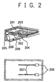
- FIG. 2 shows the constitution of an example of a typical conventional solar cell module (or a solar cell panel).
- reference numeral 201 indicates a surface side covering member
- reference numeral 202 an inside filler
- reference numeral 203 a photovoltaic element
- reference numeral 204 a back side covering member
- reference numeral 205 a frame
- Reference numeral 206 indicates a terminal box for outputting a power which is provided at a rear face of the back protective member 204.
- Reference numeral 207 indicates a connection capable which is extended from the terminal box 206.
- the front side protective member 201 comprises a tempered glass plate having a thickness of about 3 mm.
- the back side covering member 204 comprises a resin film having weatherability such as a TEDLAR [trademark name, comprising PVF (polyvinyl fluoride)] film.
- the inside filler 202 is interposed between the front side protective member 201 and the back side covering member 204, where the photovoltaic element 203 is sealed by the inside filler 202.
- EVA resin ethylene-vinyl acetate copolymer
- excelling in weatherability is used in many cases.
- Japanese unexamined Patent Publication No. 86066/1996 discloses that when a fire is occurred near the building, the fire is spread to the building, and the solar cell module situated on the roof thereof is exposed to a flame or heat radiated from the spreading fire, there is a fear that the glass plate of the solar cell module is broken due to the flame or heat, where the EVA as the inside filler is heat-fused or burned to flow to the outside.
- Japanese Unexamined Patent Publication No. 148614/1997 discloses that when a fire is occurred near the building and the fire is spread to the building, there is a fear that the glass plate as the front side protective member of the solar cell module is broken due to heat radiated from or flame of the spreading fire, where the broken glass plate is scattered or the EVA as the inside filler is heat-fused to flow to the outside to cause firing at the underlayment of the roof.
- the solar cell module in the case where the solar cell module is used as a power generation source by installing on the roof of the building, it takes such a manner as will be described in the following. That is, there are provided a number of given solar cell modules, a predetermined number of these solar cell modules are electrically connected with each other in series connection to obtain a plurality of solar cell module strings, and these solar cell module strings are electrically connected with each other by means of string cables to establish a solar cell array on the roof.
- the present invention is aimed at solving the foregoing problems upon installing a solar cell module on a desired installation place such as a roof of a building in the prior art.
- Another object of the present invention is to provide an installation structure of a solar cell module array, an installation method for installing solar cell modules, and a wiring method for wiring string cables of solar cell module strings which are free of foregoing problems in the prior art, and also a desirable sunlight power generation system.
- a further object of the present invention is to provide an installation structure of a solar cell module array, an installation method for installing solar cell modules, a wiring method for wiring string cables of solar cell module strings, and a sunlight power generation system in which an ordinary execution worker can efficiently perform desirable wiring so that no defect is occurred in the completed wiring .
- a further object of the present invention is to provide an installation structure of a solar cell module array in which a plurality of solar cell module strings are arranged on a desired installation place, said plurality of solar cell module strings having a plurality of solar cell modules, an inter solar cell module connection cable to electrically connect said plurality of solar cell modules, a positive string cable and a negative string cable, characterized in that a non-contacting means is provided such that no contact is occurred between said positive string cable and said negative string cable or between said inter solar cell module connection cable and said positive string cable or/and said negative string cable.
- a further object of the present invention is to provide an installation method of a solar cell module array, comprising arranging a plurality of solar cell module strings on a desired place, said plurality of solar cell module strings having a plurality of solar cell modules, an inter solar cell module connection cable to electrically connect said plurality of solar cell modules, a positive string cable and a negative string cable, characterized in that a non-contacting means is provided such that no contact is occurred between said positive string cable and said negative string cable or between said inter solar cell module connection cable and said positive string cable or/and said negative string cable.
- a further object of the present invention is to provide an installation structure of a solar cell module array in which a plurality of solar cell module strings are arranged on a desired installation place, said plurality of solar cell module strings having a plurality of solar cell modules, an inter solar cell module connection cable to electrically connect said plurality of solar cell modules, a positive string cable and a negative string cable, characterized in that said plurality of solar cell modules and each of said inter solar cell module connection cable, said positive string cable and said negative string cable are arranged such that no contact is occurred between said positive string cable and said negative string cable or between said inter solar cell module connection cable and said positive string cable or/and said negative string cable.
- a further object of the present invention is to provide an installation method of a solar cell module array, comprising arranging a plurality of solar cell module strings on a desired installation place, said plurality of solar cell module strings having a plurality of solar cell modules, an inter solar cell module connection cable to electrically connect said plurality of solar cell modules, a positive string cable and a negative string cable, characterized in that said plurality of solar cell modules and each of said inter solar cell module connection cable, said positive string cable and said negative string cable are arranged such that no contact is occurred between said positive string cable and said negative string cable or between said inter solar cell module connection cable and said positive string cable or/and said negative string cable.
- a further object of the present invention is to provide a sunlight power generation system comprising any of the above described solar cell module installation structure and an inverter.
- the present invention is to solve the foregoing problems found in the prior art and to attain the above described objects.
- a principal feature of the present invention is to prevent mutual contact of wiring cables in establishing a solar cell module array on an installation place (or an installation face) by (a) a contact-preventing method by way of a specific non-contact means or (b) a contact-preventing method by way of specific non-contact arrangement for the wiring cables or solar cell modules.
- a solar cell module array is established by arranging a plurality of solar cell module strings on a given installation place such as a roof of 8 building, electrically connecting them with each other by means of a pair of a positive string cable and a negative string cable, and drowing the positive and negative string cables into, for instance, the inside of the building through an entrapment hole, where they are electrically connected to an inverter.
- each of the solar cell module strings comprises a plurality of solar cell modules electrically connected with each other in series connection by means of an inter solar cell module connection cable (hereinafter referred to as "inter module connection cable”), where the inter module connection cable wired among the solar cell modules has a pair of extended opposite portions which serve as a pair of power output terminal, i.e., a positive power output terminal and a negative power output terminal of the solar cell module string.
- inter module connection cable an inter solar cell module connection cable
- the solar cell module strings are electrically connected with each other by connecting their positive power output terminals to the positive string cable and connecting their negative power output terminals to the negative string cable.
- a partition plate 906 made of an incombustible material is provided in the entrapment hole 905 so that the entrapment hole has two spaces divided by the partition plate 906.
- the positive string cables and the negative string cables are separately taken in the entrapment hole 905 such that the former passes through one of the two spaces of the entrapment hole and the latter passes through the other space of the entrapment hole. By this, mutual contact among the cables having a different polarity is prevented.
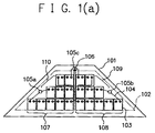
- FIG. 1(a) is a schematic view illustrating an example of an installation structure of a solar cell module array in which a plurality of roofing material-integral type solar cell modules are arranged on a trapezoidal roof face so that the solar cell modules arranged in one arrangement row and those arranged in the other arrangement row are completed in terms of their edge lines in a direction perpendicular to a horizontal line.
- reference numeral 101 indicates an installation face (a roof face) of a building (not shown).
- reference numeral 102 an installable area
- reference numeral 103 a solar cell module
- reference numeral 104 a string cable
- reference numeral 106 an incombustible member (an incombustible partition plate).
- Reference numeral 107 indicates a first solar cell module string
- reference numeral 108 a second solar cell module string
- reference numeral 109 a third solar cell module string
- reference numeral 110 a fourth solar cell module string.
- solar cell modules 103 are arranged in a first row, 6 solar cell modules 103 are arranged in a second row, and 4 solar cell modules 103 are arranged in a third row, where these solar cell modules are wired such that five of them are electrically serialized to form one string and four strings are electrically connected in parallel connection.
- each of the first to fourth strings 107 to 110 is formed by electrically serializing five of the solar cell modules 103.
- the first to fourth strings 107 to 110 are electrically connected with each other in parallel connection by means of string cables 104.
- the roof face 101 is provided one entrapment hole 105c on its ridge side for the string cables 104 extending from the strings 107 to 110 are drawn into the inside of the building by passing them through the entrapment hole 105c.
- the roof face 101 is also provided with two entrapment holes 105a and 105b each situated at a given position of each of its left and right sides, where given string cables 104 are passed through the entrapment holes 105a and 105b and they are connected respectively to a junction box (not shown).
- the positive string cables 104 extending from the first and fourth strings 107 and 110 are passed through the entrapment hole 105a situated on the left side in the figure, and the negative string cables 104 extending from the second and third strings 108 and 109 are passed through the entrapment hole 105b situated on the right side in the figure.
- an incombustible partition plate 106 comprising an incombustible member such as a gypsum board or a steel plate coated by an incombustible material is inserted to form a left side space and a right side space (in the figure) divided by the partition plate 106.
- the negative string cables 104 extending from the first and fourth strings 107 and 110 are drawn into the inside of the building by passing them through the left side space of the entrapment hole 105c, and the positive string cables 104 extending from the second and third strings 108 and 109 are drawn into the inside of the building by passing them through the right side space of the entrapment hole 105c.
- a roofing material is provided.
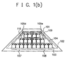
- FIG. 1(b) is a schematic view illustrating another example of an installation structure of a solar cell module array in which a plurality of roofing material-integral type solar cell modules are arranged on a trapezoidal roof face so that the solar cell modules arranged in one arrangement row and those arranged in the other arrangement row are completed in terms of their edge lines in a direction perpendicular to a horizontal line.
- FIG. 1(b) The constitution of this embodiment shown in FIG. 1(b) is the same as that of the embodiment shown in FIG. 1(a), except that the arrangement manner of the string cables is changed, and the number of the entrapment holes to be used and their positions are changed.
- two entrapment holes 105d and 105e are provided on the ridge side of the roof face 101, and the positive string cables and the negative string cables are drawn into the inside of the building by separately passing them respectively through one of the entrapment holes 105d and 105e. That is, in this embodiment, one string cable having a given polarity is passed through one entrapment hole and the other string cable whose polarity is different from that of the former is passed through the other entrapment hole.
- any materials can be used as long as they are incombustible.
- any materials can be mentioned coated metallic members, gypsum boards, tiles, cement plates, heat-resistant seals, and the like.
- the solar cell module 103 there can be mentioned, for example, a solar cell module having such a configuration as shown in FIGs. 3(a) and 3(b) and a solar cell module having such a configuration as shown in FIGs. 3(c) and 3(d).
- FIG. 3(a) is a schematic slant view of illustrating an example of a framed type solar cell module.
- FIG. 3(b) is a schematic view illustrating the back face of the solar cell module shown in FIG. 3(a).
- the framed type solar cell module comprising a solar cell module body whose peripheral portion is supported by an aluminum frame 306 having a meshing portion with a cross section in a ⁇ form.
- the solar cell module body comprising a photovoltaic element group 303 (comprising a plurality of photovoltaic elements electrically connected with each other) encapsulated in a filler 302 and which is sealed between a surface side covering member 301 (comprising a tempered glass) and a back side covering member 304.
- Reference numeral 312 indicates a sealing member comprising an insulating material which is provided at the rear face of the back side covering member 304 for the purpose of tightly sealing between the solar cell module body and the supporting means (the frame body 306) in order to prevent water
- a pair of terminal boxes 307 having a connection cable 308, and a pair of power output terminals (not shown) of the photovoltaic element group 303 are extended to connect to the terminal boxes 307.
- a fixing penetration 311 is provided at each of the lower left and right side portions of the frame 306, and the frame 306 is directly fixed to a roof bed (not shown) using the fixing penetrations 311 and by means of fixing materials such as tapping screws.
- FIG. 3(c) is a schematic slant view of illustrating an example of a roofing material-integral type solar cell module having a surface side covering member 301 (comprising a resin film having weatherablity) and a back face reinforcing member 305, viewed from the back side of the solar cell module.
- the roofing material-integral type solar cell module has opposite side end potions 390 and 310 having no photovoltaic element therein, where the side end portion 390 is downward bent by way of roll forming so as to serve as an eaves side meshing means and the side end portion 310 is upward bent by way of roll forming so as to serve as a ridge side meshing means.
- a pair of terminal boxes 307 having a connection cable 308 are provided on the back face of back side reinforcing member 305.
- FIG. 3(d) is a schematic cross-sectional view, taken along the line A-A' in FIG. 3(c).
- a solar cell module body comprising a photovoltaic element group 303 comprising a plurality of photovoltaic elements electrically connected with each other) encapsulated in a filler 302 and which is sealed between the surface side covering member 301 and a back side covering member 304.
- the back face reinforcing member 305 is laminated on the rear face of the back side covering member 304.
- the photovoltaic element comprises at least a photoelectric conversion layer formed on a substrate having an electrically conductive face.
- the photoelectric conversion layer may be a single-crystalline silicon series photoelectric conversion layer, a polycrystalline silicon series photoelectric conversion layer, a microcrystalline silicon series photoelectric conversion layer, an amorphous silicon series photoelectric conversion layer, or a compound semiconductor series photoelectric conversion layer.
- the substrate may comprise a metal substrate, a glass substrate having a surface applied with electrically conductive treatment, a resin substrate having a surface applied with electrically conductive treatment, or a substrate comprising a silicon crystal film.
- Photovoltaic Element Group 303
- An photovoltaic element has a limitation in terms of the electric performance. Therefore, it is desired to use a plurality of photovoltaic element by electrically connecting them with each other into an assembled body.
- This assembled body corresponds the photovoltaic element group 303 in the present invention.
- the electrical connection among said plurality of photovoltaic elements may be conducted by way of series connection, parallel connection, or a combination of series connection and parallel connection.
- the photovoltaic element group 303 In order for the photovoltaic element group 303 to output a high power, it is desired that the photovoltaic elements involved are electrically connected with each other in series connection.
- the photovoltaic element group 303 in the solar cell module may be replaced by one photovoltaic element.
- the surface side covering member 301 is required to have performance in order to ensure the long reliability of the solar cell module when exposed to environments in outdoors over a long period of time.
- the surface side covering member is required to excel in weatherability (including moisture resistance), pollution resistance, transparency, physical strength and durability. Therefore, the surface side covering member is necessary to comprise a material which satisfies the above requirements.
- tempered glasses and fluorine-containing resins (fluororesins) such as polyvinyl fluoride resin, polyvinylidene fluoride resin, and tetrafluoroethyleneethylene copolymer (ETFE).
- fluorine-containing resins fluororesins
- ETFE tetrafluoroethyleneethylene copolymer
- the surface side covering member is not always necessary to be provided so as to cover the entire front surface of the filler layer 302 in which the photovoltaic element group 303 is enclosed as long as the foregoing performance for the solar cell module is ensured, where it is possible for the surface side covering member to be provided such that it covers a necessary area of the front surface of said filler layer.
- the filler 103 is required to comprise a material which excels in weatherability, adhesion, heat resistance, cold resistance, and shook resistance, and also in packing performance.
- a material which excels in weatherability, adhesion, heat resistance, cold resistance, and shook resistance, and also in packing performance.
- EVA ethylene-vinyl acetate copolymer
- EEA ethylene-ethyl acrylate copolymer
- polyolefin resins urethane resins
- silicone resins silicone resins
- fluororesins fluororesins.
- EVA is the most appropriate because it exhibits well-balanced physical properties when used in a solar cell module.
- the back side covering member 304 is desired to comprise a member which excels particularly in insulating characteristic and durability.
- a member which excels particularly in insulating characteristic and durability are resin films excelling in insulating characteristic and durability such as nylon film, TEDLAR [trademark name, comprising PVF (polyvinyl fluoride)] film, and PET (polyethylene terephthalate) film.
- the back face reinforcing member 305 is required to excel particularly in weatherability, rigidity, and flexibility.
- the back face reinforcing member 305 is necessary to comprise a member which satisfies these requirements.
- Such member can include stainless steel sheets, plated steel sheets, galvanized steel sheets, and the like.
- the back side covering member 304 is not always necessary to be provided.
- the frame 306 is desired to comprise a long side member comprising an aluminum applied with alumite treatment or a galvanized steel.
- the long side member may be structured in a hallow form or a ⁇ -like form. These forms are selectively adopted depending upon the configuration of a solar cell module used.
- the terminal boxes 307 having the connection cable 308 are provided in the solar cell module in order to output an electric power (a D.C. power) generated in the solar cell module.
- the terminal box 307 is required to excel in heat resistance, moisture resistance, water proof, electrically insulating properties, cold resistance, resistance to oil, weatherability, and mechanical strength.
- the terminal box is desired to be constituted by a material which satisfies these requirements and which has good adhesion with an adhesive.
- fire-resistant plastics are particularly preferable.
- Such plastic can include engineering plastics which excel in physical strength, shock resistance, heat resistance, hardness, and aging resistance.
- Specific examples are polycarbonate, polyamide, polyacetal, modified PP0 (denaturalization polyphenylene oxide), polyester, polyarylate, unsaturated polyester, phenol resin, and epoxy resin.
- thermoplastics such as ABS resin (acrylonitrile butdiene styrene polymer), PP (polypropylene), and PV (polyvinyl chloride) are also usable depending upon the situation involved.
- ABS resin acrylonitrile butdiene styrene polymer
- PP polypropylene
- PV polyvinyl chloride
- a resin coating material having a property to absorb ultraviolet ray is applied on the surface.
- connection cable 308 used in the present invention.
- connection cable it is necessary to selectively use an appropriate cable having a desired cable structure and which has relevant heat resistance to the environment where the solar cell module is installed, specifically, which is good enough with respect to heat resistance, cold resistance, resistance to oil, weatherability, and fire-resistance.
- insulating cables such as IV cable, KIV cable, HKIV cable, crosslinked polyethylene cable, fluoro rubber cable, silicone rubber cable, and fluororesin cable.
- VV cable, CV cable, CE cable, EE cable and cabtyre cable are also usable.
- connection cable 308 may be used also as the foregoing inter module connection cable and also as the foregoing string cable.
- an assembled circuit comprising a plurality of solar cell modules (103) electrically serialized with each other in order to provide a solar cell module array which satisfies a desired output voltage is termed "solar cell module string" in the present invention.
- the voltages of the solar cell module strings 107-110 are set so that the sum of the voltages falls within an input voltage range of the inverter.
- solar cell module array a configuration in which a plurality of solar cell module strings (107, 108, 109, 110) are electrically connected with each other in parallel connection in order to obtain a desired output power.
- solar cell module string will be hereinafter referred to as “string” for the simplification purpose.
- the string cables 104 from the strings 107-110 are taken into the inside of the building through the entrapment holes (105a, 105b; or 105c, 105d), they are electrically connected to a junction box provided in the inside of the building where they are subjected to parallel operation, followed by being electrically connected to an inverter where the D.C. power inputted therein is converted into an A.C. power.
- each of the cables used to electrically connect the positive and negative terminals of each of the strings 107-110 to the junction box in order to electrically connect the strings 107-110 in parallel connection is termed "string cable” in the present invention.
- string cable the cables previously mentioned as the examples of the connection cable 308 may be selectively used.
- the string cables 104 are drawn in the inside of the building by passing them through the entrapment holes (105a, 105b; or 105c, 105d) as above described.
- the hole through which the string cables of the solar cell module array established on the installation face 101 are drawn to electrically connect to the junction box provided in the inside of the building is termed "entrapment hole”.
- the entrapment hole (105a, 105b, 105c, 105d) may be provided at a desired position of a sheathing board of the roof. Alternatively, it may be provided at a desired position of an edge of the eaves of the roof, a verge of the roof, or a ridge of the roof.
- the installation face is meant a face on which the solar cell module is installed.
- the installation face mainly indicates a roof face of a building. But this is not limitative.
- roof face in a normal trapezoidal form of a building as shown in FIG. 1(a), having a base (an eaves) with a length of 12000 mm, an upper hem (a ridge) with a length of 3640 mm, and a length in a roof flow direction (hereinafter referred to as "roof flow direction length") of 4957 mm.
- An installable area (range) in a normal trapezoidal form of the roof face is that an interval of 500 mm is present between the base of the installable area and that of the roof face and also between the upper hem of the installable area and that of the roof face, and an interval of 300 mm is present between each of the verges of the installable area and that of the roof face.
- a plurality of roofing material-integral type solar cell modules of the configuration shown in FIGs. 3(c) and 3(d) and having a lateral length [in a horizontal direction in FIG. 1(a)] of 822 mm and a vertical length [in a vertical direction in FIG. 1(a)] of 1220 mm were arranged on the trapezoidal installable area of the roof face so that the solar cell modules arranged in one arrangement row and those arranged in the other arrangement row were completed in terms of their edge lines in a direction perpendicular to a horizontal line.
- reference numeral 101 indicates the above described roof face
- reference numeral 102 the above described installable area
- reference numeral 103 the above described solar cell module
- reference numeral 104 a string cable
- each of reference numerals 105a to 105c an entrapment hole
- reference numeral 106 an incombustible member (an incombustible partition plate).
- Reference numeral 107 indicates a first solar cell module string
- reference numeral 108 a second solar cell module string
- reference numeral 109 a third solar cell module string
- reference numeral 110 a fourth solar cell module string.
- the maximum installable arrangement row number is computed to be 3 rows.
- computation will be made of the first, second, and third rows from the base of the installable area 102.
- maximum solar cell module installable number (hereinafter referred to as "maximum solar cell module installable number") in each arrangement row can be computed as follows.
- the maximum solar cell module installable number in each arrangement row can be computed in accordance with the following equation.
- the upper hem length of each arrangement row of the installable area 102 in which the solar cell modules are arranged is expressed by the term "row's upper hem length for the simplification purpose.
- the maximum solar dell module installable number is expressed by the term "maximum installable number" for the simplification purpose.
- the row's upper hem length of the first arrangement row is 8499 mm, that of the second arrangement row is 6442 mm, and that of the third arrangement row is 4384 mm. And the lateral length of each solar cell module is 822 mm.
- the maximum installable number of the solar cell modules in the first arrangement row is 10, that in the second arrangement row is 7, and that in the third arrangement row is 5.
- module series number The number of solar cell modules capable of being serialized per one string (this number will be hereinafter referred to as "module series number") can be computed in accordance with the following equations. 130/(minimum Vpm of one solar cell module) ⁇ the module series number 320/(maximum Voc of one solar cell module) ⁇ the module series number
- Each of the solar cell modules used in this embodiment has a minimum Vpm of 26.2 V and a maximum Voc of 33.0 V.
- the module series number is 5 to 9.
- 5 to 9 of the solar cell modules are electrically serialized per one string (one solar cell module string).
- 20 of the solar cell modules can be arranged on the installable area 102 of the roof face 101. That is, by making the solar cell modules involved such that that five of them are serialized per one string and five strings are electrically connected in parallel connection, the 20 solar cell modules can be installed on the roof face.
- a first string 107 (a first solar cell module string), a second string 108 (a second solar cell module string), a third string 109 (a third solar cell module string) and a fourth string 110 (a fourth solar cell module string) respectively comprising the five solar cell modules electrically serialized were formed. And in accordance with the wiring manner previously described with reference to FIG. 1(a), a first string 107 (a first solar cell module string), a second string 108 (a second solar cell module string), a third string 109 (a third solar cell module string) and a fourth string 110 (a fourth solar cell module string) respectively comprising the five solar cell modules electrically serialized were formed. And in accordance with the wiring manner previously described with reference to FIG.
- the string cables 104 extending from these strings were drawn into the inside of the building by passing them respectively through the two entrapment holes 105a and 105b provided on the left and right sides of the roof face and the entrapment hole 105c provided on the ridge side of the roof face, and the string cables 104 thus drawn into the inside of the building were electrically connected to a junction box provided there, which is electrically connected to the foregoing inverter provided also in the inside of the building.
- the positive string cables and the negative string cables were wired so that the former and the later were not crossed or contacted with each other as shown in FIG. 1(a).
- an incombustible partition plate 106 comprising an incombustible member such as a gypsum board or a steel plate coated by an incombustible material was inserted to form a left side space and a right side space divided by the partition plate 106.
- the positive string cables 104 extending from the first string 107 and the fourth string 110 were passed through the entrapment hole 105a on the left side in the figure, and the negative string cables 104 extending from the second string 108 and the third string 109 were passed through the entrapment hole 105b provided on the right side in the figure.
- the negative string cables 104 extending from the first string 107 and the fourth string 110 were drawn into the inside of the building by passing them through the left side space of the entrapment holes 105c, and the positive string cables 104 extending from the second string 108 and the third string 109 were passed through the entrapment hole 105b situated on the right side in the figure.
- Example 1 The procedures of Example 1 were repeated, except that the arrangement manner of the string cables was changed, and the number of the entrapment holes to be used and their positions were changed as shown in FIG. 1(b).
- two entrapment holes 105d and 105e were provided on the ridge side of the roof face 101. And the positive string cables were drawn into the inside of the building by passing them through the entrapment hole 105d provided on the left side in the figure and the negative string cables were drawn into the inside of the building by passing them through the entrapment hole 105e provided on the right side in the figure.
- a bridge member 501 comprising an incombustible material (a steel sheet coated by an incombustible insulating material was provided at a portion where the different string cables having a different polarity would be contacted with each other. By this, it is possible to prevent these string cables from being contacted with each other.
- a gable roof face 1101 of a building as shown in FIG. 10 having a base (an eaves) with a length of 10000 mm, an upper hem (a ridge) with a length of 10000 mm, and a length in a roof flow direction (hereinafter referred to as "roof flow direction length") of 4500 mm.
- An installable area 1002 (an installable range) of the roof face is that substantially no interval is present between the base of the roof face and that of the installable area, an interval of 200 mm is present between the upper hem of the roof face and that of the installable area, and an interval of 100 mm is present between each of the verges of the roof face and the boundary of each of opposite sides of the installable area.
- a plurality of solar cell modules (each comprising 8 photovoltaic elements electrically serialized with each other) each having a pair of an positive terminal box and a negative terminal box respectively provided at one of end portions of the back face and having a working width of 200 mm and a length of 2000 mm were arranged on the installable area 1002 of the roof face 1001 by an every other shift-roofing method as shown in FIG. 10.
- reference numeral 1001 indicates the foregoing roof face (corresponding to an installation face), reference numeral 1002 the foregoing installable area, reference numeral 1003 a solar cell module, reference numeral 1004 a positive string cable, reference numeral 1005 a negative string cable, reference numeral 1006 an entrapment hole, and reference numeral 1007 a partition plate comprising an incombustible insulating material.
- Reference numeral 1008 indicates a 1st string (a 1st solar cell module string), reference numeral 1009 a 2nd string (a 2nd solar cell module string), reference numeral 1010 a 3rd string (a 3rd solar cell module string), reference numeral 1011 a 4th string (a 4th solar cell module string), reference numeral 1012 a 5th string (a 5th solar cell module string), reference numeral 1013 a 6th string (a 6th solar cell module string), and reference numeral 1014 a 7th string (a 7th solar cell module string).
- the arrangement row number is a maximum integer obtained by the following equation.
- the maximum installable arrangement row number is computed to be 21 rows.
- the maximum installable number of solar cell modules in each arrangement row (hereinafter referred to as "maximum solar cell module installable number" for the simplification purpose) is a maximum integer obtained by the following equation.
- the length of one solar cell module is 2000 mm.
- the maximum installable number of solar cell modules in each arrangement row is computed to be 4 (solar cell modules).
- the shift difference width between the solar cell module group in one arrangement row and that in the other arrangement row situated next to said arrangement row was made to be 200 mm.
- the solar cell module groups in the respective arrangement rows were positioned such that their arrangement positions were alternately shifted by 100 mm on either side.
- module series number The number of solar cell modules capable of being serialized per one string (this number will be hereinafter referred to as "module series number") can be computed in accordance with the following equations. 100/(minimum Vpm of one solar cell module) ⁇ the module series number 350/(maximum Voc of one solar cell module) ⁇ the module series number
- Each of the solar cell modules 1003 used in this embodiment has a minimum Vpm of 1.28 V and a maximum Voc of 2.12 V.
- the module series number is 79 to 165.
- 10 to 20 of the solar cell modules 1003 are electrically serialized per one string (one solar cell module string).
- the strings involved were arranged as follows. That is, the arrangement of one of every two other solar cell module groups comprising 4 of the solar cell modules in the respective arrangement rows is shifted by 100 mm toward the left verge side so that the negative terminal of one left-sided solar cell module of the solar cell module group involved is exposed on the left verge side and the arrangement of each of the remaining solar cell module groups is shifted by 100 mm toward the right verge side so that the negative terminal of one right-sided solar cell module of the solar cell module group involved is exposed on the right verge side as shown in FIG. 10. And as shown in FIG.
- a 1st string 1008 is formed by electrically serializing the 12 solar cell modules situated in the 1st to 3rd arrangement rows
- a 2nd string 1009 is formed by electrically serializing the 12 solar cell modules situated in the 4th to 7th arrangement rows
- a 3rd string 1010 is formed by electrically serializing the 12 solar cell modules situated in the 8th to 10th arrangement rows
- a 4th string 1011 is formed by electrically serializing the 12 solar cell modules situated in the 11th to 13th arrangement rows
- a 5th string 1012 is formed by electrically serializing the 12 solar cell modules situated in the 15th to 17th arrangement rows
- a 6th string 1013 is formed by electrically serializing the 12 solar cell modules situated in the 18th to 21st arrangement rows
- a 7th string 1014 is formed by electrically serializing the 12 solar cell modules situated in the 22nd to 24th arrangement rows.
- the negative string cables 1004 and the positive string cables 1005 were drawn into the inside of the building by passing them through the entrapment hole 1006, and the string cables thus drawn into the inside of the building were electrically connected to a junction box provided there, which is electrically connected to the foregoing inverter provided also in the inside of the building.
- the entrapment hole 1006 was provided on the ridge side of the roof face 1001 as shown in FIG. 10, and in the entrapment hole 1006, an incombustible partition plate 107 comprising an incombustible member such as a gypsum board or a steel plate coated by an incombustible insulating material was inserted to form a left side space and a right side space divided by the partition plate 1007.
- an incombustible partition plate 107 comprising an incombustible member such as a gypsum board or a steel plate coated by an incombustible insulating material was inserted to form a left side space and a right side space divided by the partition plate 1007.
- the negative string cables 1004 and the positive string cables 1005 were separately drawn into the inside of the building by passing the former through one of the left side and right side spaces of the entrapment hole 1006 and passing the later through the remaining space of the entrapment hole.
- the negating string cables 1004 and the positive string cables 1005 in the entrapment hole 1006 can be prevented from being contacted with each other.
- a lipped-roof face 1101 of a building as shown in FIG. 11(a), having a base (an eaves) with a length of 12000 mm, an upper hem (a ridge) with a length of 5000 mm, and a length in a roof flow direction (hereinafter referred to as "roof flow direction length") of 4500 mm.
- An installable area 1102 (an installable range) of the roof face 1101 is that substantially no interval is present between the base of the roof face and that of the installable area, an interval of 200 mm is present between the upper hem of the roof face and that of the installable area, and an interval of 200 mm is present between each of the verges of the roof face and the boundary of each of opposite aides of the installable area.
- a plurality of solar cell modules each comprising 8 photovoltaic elements electrically serialized with each other
- each having a pair of an positive terminal box and a negative terminal box respectively provided at one of end portions of the back face and having a working width of 200 mm and a length of 2000 mm were arranged on the installable area 1102 of the roof face 1101 by an every other shift-roofing method as shown in FIG. 11(a).
- reference numeral 1101 indicates the foregoing roof face (corresponding to an installation face), reference numeral 1102 the foregoing installable area, reference numeral 1103 a solar cell module, reference numeral 1105 an entrapment hole, and reference numeral 1106 an incombustible insulating material (or a partition plate), and reference numeral 1107 a string cable.
- Reference numeral 1104 a 1st string (a 1st solar cell module string), reference numeral 1108 a 2nd string (a 2nd solar cell module string), reference numeral 1109 a 3rd string (a 3rd solar cell module string), and reference numeral 1110 a 4th string (a 4th solar cell module string).
- Reference numeral 103' a solar cell module which is the same as said solar cell module 1103. This reference numeral 103' is used for identifying each of given two solar cell modules situated to next each other in the explanation which will be described later.
- the arrangement row number is a maximum integer obtained by the following equation.
- the maximum installable arrangement row number is computed to be 21 rows.
- the maximum installable number of solar cell modules in each arrangement row (hereinafter referred to as "maximum solar cell module installable number" for the simplification purpose) is a maximum integer obtained by the following equation (IX).
- B is a value obtained by subtracting a shifted width of a solar cell module group in each arrangement row from the length of the installable area of said arrangement row.
- said shifted width is made to be 200 mm.
- the maximum solar cell module installable number in each of let to 4th arrangement rows is 5 solar cell modules, that in each of 5th to 10th arrangement rows is 4 solar cell modules, that in each of 11th to 17th arrangement rows is 3 solar cell modules, and that in each of 18th to 21th arrangement rows is 2 solar cell modules.
- the shift difference width between the solar cell module group in one arrangement row and that in the other arrangement row situated next to said arrangement row was made to be 200 mm.
- the solar cell groups in the respective arrangement rows were positioned such that their arrangement positions were alternately shifted by 100 mm on either side.
- module series number The number of solar cell modules capable of being serialized per one string (this number will be hereinafter referred to as "module series number") can be computed in accordance with the following equations. 100/(minimum Vpm of one solar cell module) ⁇ the module series number 350/(maximum Voc of one solar cell module) ⁇ the module series number
- Each of the solar cell modules 1103 used in this embodiment has a minimum Vpm of 1.28 V and a maximum Voc of 2.12 V.
- the module series number is 79 to 165.
- the solar cell modules 1103 in the number of 10 to 20 are electrically serialized per one string (one solar cell module string).
- the solar cell modules in the number of 73 can be arranged on the installable area 1102 of the roof face 1101. That is, by making the arrangement of the solar cell modules such that 18 of them are serialized per one string to form 4 strings [see, 1104, and 1108-110 in FIG. 11(a)] which are electrically connected in parallel connection, the solar cell modules in the number of 72, which is proximate to the above number 73, can be installed on the roof face.
- the tour strings are a 1st string 1104, a 2nd string 1108, a 3rd string 1109, and a 4th string 1110) each comprising 18 of the solar cell modules electrically serialized through an inter module connection cable.
- the arrangement of the 1st string 1104 is terminated enroute in the fourth arrangement row, where the 2nd string 1108 is started.
- the last solar cell, module 1103 of the 1st string 1104 is unavoidably approximated to the beginning solar cell module 1103' (1103) of the 2nd string 1108, where the string cable 1107 extending from the terminal of solar cell module 1103 of the 1st string 1104 and that extending from the terminal of the solar cell module 1103' of the 2nd string 1108 are liable to be contacted with each other.
- the polarity of the former string cable is different from that of the latter string cable, there is a fear that electric short is occurred between them.
- the two string cables situated to next each other were made to be of the same polarity by making the solar cell modules (including the solar cell module 1103 involved) of the 1st string 1104 situated in the fourth arrangement row to be of the left positive terminal type and making the solar cell modules (including the solar cell module 1103' involved) of the 2nd string 1108 situated in the fourth arrangement row to be of the right positive terminal type as shown in FIG. 11(a).
- an incombustible partition plate 1106 comprising an incombustible member such as a gypsum board or a steel plate coated by an incombustible insulating material was inserted to form a left side space and a right side space divided by the partition plate 1106.
- the negative string cables and the positive string cables were separately drawn into the inside of the building by passing the former through one of the left side and right side spaces of the entrapment hole 1105 and passing the later through the remaining space of the entrapment hole.
- the negating string cables and the positive string cables in the entrapment hole 1105 can be prevented from being contacted with each other.
- Example 4 The procedures of Example 4 were repeated, except that the arrangement manner of the string cables was changed, and the number of the entrapment hole to be used and its positions were changed as shown in FIG. 11(b).
- one entrapment hole 1105 was provided at a central position of the ridge portion of the roof face 1101.
- a partition means 1106 comprising an incombustible insulating sealing member was inserted to form a left side space and a right side space divided by the partition means 1106.
- the negative string cables and the positive string cables were separately drawn into the inside of the building by passing the former through one of the left side and right side spaces of the entrapment hole 1105 and passing the later through the remaining space of the entrapment hole.
- the upper portion of the entrapment hole could be covered by the incombustible insulating sealing member.
- a gable roof face 1201 of a building as shown in FIG. 12 having a base (an eaves) with a length of 10000 mm, an upper hem (a ridge) with a length of 10000 mm, and a length in a roof flow direction (hereinafter referred to as "roof flow direction length") of 4000 mm.
- An installable area 1202 (an installable range) of the roof face 1201 is that substantially no interval is present between the base of the roof face and that of the installable area, an interval of 300 mm is present between the upper hem of the roof face and that of the installable area, and an interval of 100 mm is present between each of the verges of the roof face and the boundary of each of opposite sides of the installable area.
- a plurality of solar cell modules (each comprising 8 photovoltaic elements electrically serialized with each other) each having a pair of an positive terminal box and a negative terminal box respectively provided at one of end portions of the back face and having a working width of 200 mm and a length of 2000 mm were arranged on the installable area 1202 of the roof face 1201 by an every other shift-roofing method as shown in FIG. 12.
- reference numeral 1201 indicates the foregoing roof face (corresponding to an installation face), reference numeral 1202 the foregoing installable area, reference numeral 1203 a solar cell module, reference numeral 1204 a string cable, reference numeral 1205 an entrapment hole, and reference numeral 1206 an incombustible insulating material as a partition means, and reference numeral 1207 a inter module connection cable.
- Reference numeral 1208 indicates a 1st string (a 1st solar cell module string), reference numeral 1209 a 2nd string (a 2nd solar cell module string), reference numeral 1210 a 3rd string (a 3rd solar cell module string), and reference numeral 1211 a 4th string (a 4th solar cell module string).
- the solar cell modules 1203 arranged on the installable area 1202 part of them are arranged such that their positive terminals are situated on the left side (these solar cell modules will be hereinafter referred to as “left positive terminal type solar cell module”) and the remaining part are arranged such that their positive terminals are situated on the right side (these solar cell modules will be hereinafter referred to as “right positive terminal type solar cell module”).
- the arrangement row number is a maximum integer obtained by the following equation.
- the maximum installable arrangement row number is computed to be 18 rows.
- the maximum installable number of solar cell modules in each arrangement row (hereinafter referred to as "maximum solar cell module installable number" for the simplification purpose) is a maximum integer obtained by the following equation.
- the length of one solar cell module is 2000 mm.
- the maximum installable number of solar cell modules in each arrangement row is computed to be 4 (solar cell modules).
- the shift difference width between the solar cell module group in one arrangement row and that in the other arrangement row situated next to said arrangement row was made to be 200 mm.
- the solar cell groups in the respective arrangement rows were positioned such that their arrangement positions were alternately shifted by 100 mm on either side,
- module series number The number of solar cell modules capable of being serialized per one string (this number will be hereinafter referred to as "module series number") can be computed in accordance with the following equations. 153.5/(minimum Vpm of one solar cell module) ⁇ the module series number 330/(maximum Voc of one solar cell module) ⁇ the module series number
- Each of the solar cell modules 1203 used in this embodiment has a minimum Vpm of 1.28 V and a maximum Voc of 2.12 V.
- the solar cell modules involved were installed on the installable area 1202 as follows.
- a solar cell group comprising 4 of the solar cell modules is positioned in each of the 18 arrangement rows and the 18 solar cell module groups are alternately shifted by 100 mm on either side, where these solar cell module groups are alternately differed such that the positive or negative terminals of the solar cell modules arranged in every other solar cell module group are faced toward an either side.
- every 18 solar cell modules are electrically serialized by means of an inter module connection cable 1207 to form four strings, i.e., a first string 1208, a second string 1209, a third string 1210, and a fourth string 1211.
- Each of these strings has a pair of string cables 1204 (a positive string cable and a negative string cable).
- entrapment holes 1205 in an area in the vicinity of the ridge of the roof face such that one was situated on the left side and the other was situated on the right side.
- the positive, and negative string cables 1204 extending from the first and third strings 1208 and 1210 were drawn into the inside of the building by passing them through the entrapment hole 1205 on the left side and the positive and negative string cables 1204 extending from the second and fourth strings 1209 and 1211 were also drawn into the inside of the building by passing them through the entrapment hole 1205 on the right side, where these string cables thus drawn into the inside of the building are electrically connected to a junction box provided there, which is electrically connected to the foregoing inverter also provided there.
- the positive and negative string cables extending from the respective strings were separately wired in an area with no solar cell module and between the positive and negative terminal boxes of each of the solar cell modules involved.
- an incombustible partition means 1206 comprising a gypsum board was inserted to form a left side space and a right side space divided by the partition means 1206.
- the positive and negative string cables 1204 involved were separately drawn into the inside of the building by passing one through one of the left side and right side spaces of the entrapment hole and passing the other through the remaining space of the entrapment hole.
- the partition means 1206 can be readily processed into a desired form usable as the partition means 1206 by means of an appropriate cutter.
- the partition means comprising such gypsum board member can be readily fixed to a roof bed by means of screwing or nailing or by way of bonding with the use of an adhesive.
- the provision of the partition means can be readily and efficiently conducted at a reasonable cost.
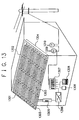
- a solar cell module array was assembled in accordance with the module-arranging method described in Example 4 to construct a system interconnection type sunlight power generation system with a reverse current flow for a residence as shown in FIG. 13.
- reference numeral 1301 indicates an roof face (an installation face), reference 1302 an installable area, reference numeral 1303 a string (a solar cell module string), reference numeral 1304 a solar cell module array, reference numeral 1305 a junction box, and reference numeral 1306 an inverter.
- Reference numeral 1307 indicates a distribution panelboard, reference numeral 1308 a load, reference numeral 1309 a watthour meter for a dump power, and reference numeral 1310 a watthour meter for a power on demand.
- the solar cell module array structure is desirably prevented from suffering electric short among the cables wired therein.
- An installation structure of a solar cell module array in which a plurality of solar cell module strings are arranged on a desired installation face, said plurality of solar cell module strings having a plurality of solar cell modules, an inter solar cell module connection cable to electrically connect said plurality of solar cell modules, a positive string cable and a negative string cable, characterized in that a non-contacting means is provided such that no contact is occurred between said positive string cable and said negative string cable or between said inter solar cell module connection cable and said positive string cable or/and said negative string cable.
- This solar cell module array installation structure excels in the safety. That is, in the array installation structure, the positive and negative string cables are wired in a desirable state so that no electric short is occurred between these two cables, even when a fire should be occurred in the vicinity of the installation face.
Landscapes
- Engineering & Computer Science (AREA)
- Architecture (AREA)
- Civil Engineering (AREA)
- Structural Engineering (AREA)
- Photovoltaic Devices (AREA)
- Roof Covering Using Slabs Or Stiff Sheets (AREA)
Applications Claiming Priority (4)
| Application Number | Priority Date | Filing Date | Title |
|---|---|---|---|
| JP4732499 | 1999-02-25 | ||
| JP4732499 | 1999-02-25 | ||
| JP2000046107A JP2000312019A (ja) | 1999-02-25 | 2000-02-23 | 太陽電池モジュールアレイ、太陽電池モジュールアレイの設置構造、太陽電池モジュールの設置方法及び太陽光発電システム |
| JP2000046107 | 2000-02-23 |
Publications (2)
| Publication Number | Publication Date |
|---|---|
| EP1032050A2 true EP1032050A2 (de) | 2000-08-30 |
| EP1032050A3 EP1032050A3 (de) | 2007-12-26 |
Family
ID=26387491
Family Applications (1)
| Application Number | Title | Priority Date | Filing Date |
|---|---|---|---|
| EP00103874A Withdrawn EP1032050A3 (de) | 1999-02-25 | 2000-02-24 | Installationsstruktur einer Anordnung von Solarzellenmodulen, Installationsmethode von Solarzellenmodulen, und Sonnenenergieerzeugungssystem |
Country Status (4)
| Country | Link |
|---|---|
| US (1) | US6331671B1 (de) |
| EP (1) | EP1032050A3 (de) |
| JP (1) | JP2000312019A (de) |
| CN (1) | CN1263127C (de) |
Cited By (1)
| Publication number | Priority date | Publication date | Assignee | Title |
|---|---|---|---|---|
| EP1263113A3 (de) * | 2001-05-31 | 2004-01-21 | Canon Kabushiki Kaisha | Solarzellenanordnung und photovoltaisches Energieerzeugungssystem |
Families Citing this family (57)
| Publication number | Priority date | Publication date | Assignee | Title |
|---|---|---|---|---|
| JP3586083B2 (ja) * | 1997-11-13 | 2004-11-10 | キヤノン株式会社 | 太陽電池モジュールの配置方法及び太陽電池モジュールアレイ |
| US6730841B2 (en) | 2001-03-14 | 2004-05-04 | United Solar Systems Corporation | Method and apparatus for mounting a photovoltaic roofing material |
| JP2002359386A (ja) | 2001-05-31 | 2002-12-13 | Canon Inc | 太陽電池ストリング、太陽電池アレイ及び太陽光発電システム |
| US6617507B2 (en) | 2001-11-16 | 2003-09-09 | First Solar, Llc | Photovoltaic array |
| US6966184B2 (en) * | 2002-11-25 | 2005-11-22 | Canon Kabushiki Kaisha | Photovoltaic power generating apparatus, method of producing same and photovoltaic power generating system |
| JP4003655B2 (ja) * | 2003-02-12 | 2007-11-07 | 三菱電機株式会社 | 太陽電池パネル |
| US7534956B2 (en) * | 2003-04-10 | 2009-05-19 | Canon Kabushiki Kaisha | Solar cell module having an electric device |
| JP2004319800A (ja) * | 2003-04-17 | 2004-11-11 | Canon Inc | 太陽電池モジュール |
| JP2004319812A (ja) * | 2003-04-17 | 2004-11-11 | Canon Inc | 電力変換器付き太陽電池モジュール |
| US6959517B2 (en) * | 2003-05-09 | 2005-11-01 | First Solar, Llc | Photovoltaic panel mounting bracket |
| JP2005150318A (ja) * | 2003-11-14 | 2005-06-09 | Canon Inc | 太陽電池モジュール及びその製造方法 |
| JP2005175197A (ja) * | 2003-12-11 | 2005-06-30 | Canon Inc | 太陽電池モジュール及びその製造方法 |
| JP2005183660A (ja) * | 2003-12-19 | 2005-07-07 | Canon Inc | 太陽電池モジュール |
| JP4681806B2 (ja) * | 2003-12-19 | 2011-05-11 | キヤノン株式会社 | 太陽電池モジュール |
| FR2864347B1 (fr) * | 2003-12-23 | 2006-03-03 | Cit Alcatel | Panneau generateur solaire et satellite associe |
| US20060042683A1 (en) * | 2004-08-31 | 2006-03-02 | Ron Gangemi | System and method for mounting photovoltaic cells |
| US8168880B2 (en) * | 2006-04-26 | 2012-05-01 | Certainteed Corporation | Shingle with photovoltaic element(s) and array of same laid up on a roof |
| US8319093B2 (en) | 2006-07-08 | 2012-11-27 | Certainteed Corporation | Photovoltaic module |
| US20080271774A1 (en) | 2007-05-01 | 2008-11-06 | Kalkanoglu Husnu M | Photovoltaic Roofing Wiring Array, Photovoltaic Roofing Wiring System and Roofs Using Them |
| AU2008266176A1 (en) * | 2007-06-19 | 2008-12-24 | Bp Corporation North America Inc. | Solar module with a frame for mounting a solar panel |
| WO2009061963A2 (en) | 2007-11-06 | 2009-05-14 | Krause Richard H | Photovoltaic roofing systems and methods for installing them |
| WO2009089236A2 (en) | 2008-01-08 | 2009-07-16 | Certainteed Corporation | Photovoltaic module |
| US20090242015A1 (en) * | 2008-03-28 | 2009-10-01 | Wattman George G | Photovoltaic Roofing Elements, Laminates, Systems and Kits |
| US20100313501A1 (en) * | 2009-06-10 | 2010-12-16 | Gangemi Ronald J | Roof mounting bracket for photovoltaic power generation system |
| US20100313499A1 (en) * | 2009-06-10 | 2010-12-16 | Gangemi Ronald J | Roof mounting bracket for photovoltaic power generation system |
| US20110048505A1 (en) * | 2009-08-27 | 2011-03-03 | Gabriela Bunea | Module Level Solution to Solar Cell Polarization Using an Encapsulant with Opened UV Transmission Curve |
| EP2617065A2 (de) * | 2010-09-17 | 2013-07-24 | Dow Global Technologies LLC | Verbesserte pv-zellenanordnung und verfahren |
| US20120067391A1 (en) | 2010-09-20 | 2012-03-22 | Ming Liang Shiao | Solar thermoelectric power generation system, and process for making same |
| US8720132B2 (en) * | 2011-01-27 | 2014-05-13 | Certainteed Corporation | Electrical wiring systems for use in roofing applications |
| US8635818B2 (en) | 2011-03-01 | 2014-01-28 | Ecolibrium Solar, Inc. | System and method for mounting photovoltaic modules |
| US11190127B2 (en) | 2011-03-01 | 2021-11-30 | Unirac, Inc. | Support assembly for photovoltaic modules and mounting system using the same |
| US10033328B2 (en) | 2011-03-01 | 2018-07-24 | Ecolibrium Solar, Inc. | Support member for mounting photovoltaic modules and mounting system including the same |
| US8869471B2 (en) | 2011-03-01 | 2014-10-28 | Ecolibrium Solar, Inc. | Support assembly for supporting photovoltaic modules |
| US10644644B2 (en) | 2011-03-01 | 2020-05-05 | Ecolibrium Solar, Inc. | Support assembly for photovoltaic modules and mounting system using the same |
| US11689148B2 (en) | 2011-03-01 | 2023-06-27 | Unirac Inc. | Support assembly for photovoltaic modules and mounting system using the same |
| US9196755B2 (en) | 2011-03-01 | 2015-11-24 | Ecolibrium Solar, Inc. | Support member for mounting photovoltaic modules and mounting system including the same |
| CN102361041A (zh) * | 2011-10-10 | 2012-02-22 | 常州市东君光能科技发展有限公司 | 太阳能电池组件 |
| US9912287B2 (en) | 2011-11-25 | 2018-03-06 | Lg Innotek Co., Ltd. | Solar cell module and method of fabricating the same |
| DE102012106130A1 (de) * | 2012-01-11 | 2013-07-11 | Fraunhofer-Gesellschaft zur Förderung der angewandten Forschung e.V. | Vereinfachte PV Anlagenerstellung mit einem fortlaufend platzierten Systemblock |
| US8844215B2 (en) | 2012-07-10 | 2014-09-30 | Ecolibrium Solar, Inc. | Support assembly for supporting photovoltaic modules |
| DE102013106255A1 (de) * | 2013-06-14 | 2014-12-18 | Phoenix Contact Gmbh & Co. Kg | Kabelmodul für Modulwechselrichter eines Photovoltaikgenerators |
| USD713784S1 (en) | 2013-06-20 | 2014-09-23 | Ecolibrium Solar, Inc. | Support member for photovoltaic modules |
| US12301159B2 (en) | 2014-11-13 | 2025-05-13 | Unirac Inc. | Modular sloped roof solar mounting system |
| US9825581B2 (en) | 2013-11-14 | 2017-11-21 | Ecolibrium Solar, Inc. | Modular sloped roof solar mounting system |
| US10727781B2 (en) | 2014-12-24 | 2020-07-28 | Ecolibrium Solar, Inc. | Low-sloped roof solar mounting systems |
| US10340837B2 (en) | 2015-03-11 | 2019-07-02 | Ecolibrium Solar, Inc | Sloped roof solar panel mounting system |
| US10312853B2 (en) | 2015-03-11 | 2019-06-04 | Ecolibrium Solar, Inc | Sloped roof solar panel mounting system |
| US10756668B2 (en) | 2015-03-11 | 2020-08-25 | Ecouni, Llc | Universal sloped roof solar panel mounting system |
| US10116256B2 (en) * | 2015-12-29 | 2018-10-30 | Solarcity Corporation | Photovoltaic modules with corner junction boxes and array of the same |
| US10230324B2 (en) | 2016-03-07 | 2019-03-12 | Ecolibrium Solar, Inc | Support assembly for photovoltaic modules and mounting system using the same |
| US10580919B2 (en) | 2017-12-07 | 2020-03-03 | Solaero Technologies Corp. | Space solar cell arrays with blocking diodes |
| US10490682B2 (en) | 2018-03-14 | 2019-11-26 | National Mechanical Group Corp. | Frame-less encapsulated photo-voltaic solar panel supporting solar cell modules encapsulated within multiple layers of optically-transparent epoxy-resin materials |
| JP2020181905A (ja) * | 2019-04-25 | 2020-11-05 | シャープ株式会社 | 太陽電池モジュール |
| CN112216755B (zh) * | 2020-08-25 | 2022-07-29 | 宣城开盛新能源科技有限公司 | 一种柔性太阳能子电池的串接工艺 |
| CN114310077B (zh) * | 2022-03-11 | 2022-05-27 | 南京莱迪新能源科技有限公司 | 一种锂电池组串并联焊接用多维度壳体模具及驱控系统 |
| JP7711116B2 (ja) * | 2023-03-02 | 2025-07-22 | シャープ株式会社 | 太陽電池モジュール |
| CN119789549B (zh) * | 2025-03-10 | 2025-07-08 | 晶科能源(海宁)有限公司 | 光伏组件 |
Citations (2)
| Publication number | Priority date | Publication date | Assignee | Title |
|---|---|---|---|---|
| EP0734111A2 (de) | 1995-03-24 | 1996-09-25 | France Telecom | Photovoltaische Hochspannungsanlage mit individuellen Speichermitteln |
| JPH10135504A (ja) | 1996-10-31 | 1998-05-22 | Tokyo Electric Power Co Inc:The | 太陽電池モジュール配線用コネクタとその接続方法 |
Family Cites Families (4)
| Publication number | Priority date | Publication date | Assignee | Title |
|---|---|---|---|---|
| JPH0886066A (ja) | 1994-07-19 | 1996-04-02 | Misawa Homes Co Ltd | 太陽電池屋根の防火構造および太陽電池パネル |
| US5590495A (en) * | 1995-07-06 | 1997-01-07 | Bressler Group Inc. | Solar roofing system |
| JPH09148614A (ja) | 1995-11-24 | 1997-06-06 | Sanyo Electric Co Ltd | 太陽電池パネル |
| JPH10135499A (ja) * | 1996-10-31 | 1998-05-22 | Tokyo Electric Power Co Inc:The | 太陽電池モジュール配線接続方法 |
-
2000
- 2000-02-23 JP JP2000046107A patent/JP2000312019A/ja active Pending
- 2000-02-24 EP EP00103874A patent/EP1032050A3/de not_active Withdrawn
- 2000-02-24 US US09/512,355 patent/US6331671B1/en not_active Expired - Lifetime
- 2000-02-25 CN CNB00106875XA patent/CN1263127C/zh not_active Expired - Fee Related
Patent Citations (2)
| Publication number | Priority date | Publication date | Assignee | Title |
|---|---|---|---|---|
| EP0734111A2 (de) | 1995-03-24 | 1996-09-25 | France Telecom | Photovoltaische Hochspannungsanlage mit individuellen Speichermitteln |
| JPH10135504A (ja) | 1996-10-31 | 1998-05-22 | Tokyo Electric Power Co Inc:The | 太陽電池モジュール配線用コネクタとその接続方法 |
Cited By (3)
| Publication number | Priority date | Publication date | Assignee | Title |
|---|---|---|---|---|
| EP1263113A3 (de) * | 2001-05-31 | 2004-01-21 | Canon Kabushiki Kaisha | Solarzellenanordnung und photovoltaisches Energieerzeugungssystem |
| US6884934B2 (en) | 2001-05-31 | 2005-04-26 | Canon Kabushiki Kaisha | Solar-battery array, and photovoltaic power generation system |
| AU783510B2 (en) * | 2001-05-31 | 2005-11-03 | Canon Kabushiki Kaisha | Solar-battery array, and photovoltaic power generation system |
Also Published As
| Publication number | Publication date |
|---|---|
| JP2000312019A (ja) | 2000-11-07 |
| CN1263127C (zh) | 2006-07-05 |
| EP1032050A3 (de) | 2007-12-26 |
| CN1274174A (zh) | 2000-11-22 |
| US6331671B1 (en) | 2001-12-18 |
Similar Documents
| Publication | Publication Date | Title |
|---|---|---|
| US6331671B1 (en) | Installation structure of solar cell module array, installation method of solar cell module, and sunlight power generation system | |
| US6606830B2 (en) | Solar cell-bearing roof and method for installing solar cell-bearing roof | |
| US6128868A (en) | Combination solar battery and roof member, and mounting method thereof | |
| US6269596B1 (en) | Roof member and mounting method thereof | |
| US7342171B2 (en) | Integrated photovoltaic roofing component and panel | |
| US6521821B2 (en) | Fixing member, a solar cell module array using said fixing member, and a method for installing a solar cell module or a roofing member using said fixing member | |
| US20050072456A1 (en) | Integrated photovoltaic roofing system | |
| US20120060902A1 (en) | System and method for frameless laminated solar panels | |
| US20140102519A1 (en) | Roof Integrated Solar Panel System with Ridge Mounted Micro Inverters | |
| JP2002141541A (ja) | 太陽光発電装置および建造物 | |
| US20110162301A1 (en) | Solar Cell Module and Solar Cell Array | |
| US20080314434A1 (en) | Photovoltaic panel | |
| US11012025B2 (en) | Interlocking BIPV roof tile with backer | |
| JP3106835B2 (ja) | 太陽光発電住宅 | |
| KR20170015363A (ko) | 광전지 디바이스가 장착된 패널 | |
| JP4565948B2 (ja) | 太陽電池モジュール | |
| JP2000252510A (ja) | 太陽電池モジュール及びその製造方法、施工方法並びに太陽光発電システム | |
| KR100357905B1 (ko) | 건축 외장용 태양광기전 모듈 | |
| JP2006140420A (ja) | 太陽電池モジュール及び設置構造 | |
| JP4326990B2 (ja) | 屋根材一体型太陽電池モジュール | |
| JP2000077700A (ja) | 太陽電池装置 | |
| JP2760599B2 (ja) | 屋根設置型太陽電池 | |
| JP3169545B2 (ja) | 太陽電池モジュール及び該太陽電池モジュールの屋根への取付方法 | |
| JP3169546B2 (ja) | 太陽電池モジュール及び該太陽電池モジュールの屋根への取付方法 | |
| JPH03124070A (ja) | 屋根設置型太陽電池 |
Legal Events
| Date | Code | Title | Description |
|---|---|---|---|
| PUAI | Public reference made under article 153(3) epc to a published international application that has entered the european phase |
Free format text: ORIGINAL CODE: 0009012 |
|
| 17P | Request for examination filed |
Effective date: 20000224 |
|
| AK | Designated contracting states |
Kind code of ref document: A2 Designated state(s): AT BE CH CY DE DK ES FI FR GB GR IE IT LI LU MC NL PT SE |
|
| AX | Request for extension of the european patent |
Free format text: AL;LT;LV;MK;RO;SI |
|
| PUAL | Search report despatched |
Free format text: ORIGINAL CODE: 0009013 |
|
| AK | Designated contracting states |
Kind code of ref document: A3 Designated state(s): AT BE CH CY DE DK ES FI FR GB GR IE IT LI LU MC NL PT SE |
|
| AX | Request for extension of the european patent |
Extension state: AL LT LV MK RO SI |
|
| 17Q | First examination report despatched |
Effective date: 20080619 |
|
| AKX | Designation fees paid |
Designated state(s): AT BE CH CY DE DK ES FI FR GB GR IE IT LI LU MC NL PT SE |
|
| STAA | Information on the status of an ep patent application or granted ep patent |
Free format text: STATUS: THE APPLICATION HAS BEEN WITHDRAWN |
|
| 18W | Application withdrawn |
Effective date: 20100311 |