EP1032067A2 - Nickel-metalhydrid Sekundärbatterie - Google Patents
Nickel-metalhydrid Sekundärbatterie Download PDFInfo
- Publication number
- EP1032067A2 EP1032067A2 EP00103378A EP00103378A EP1032067A2 EP 1032067 A2 EP1032067 A2 EP 1032067A2 EP 00103378 A EP00103378 A EP 00103378A EP 00103378 A EP00103378 A EP 00103378A EP 1032067 A2 EP1032067 A2 EP 1032067A2
- Authority
- EP
- European Patent Office
- Prior art keywords
- nickel
- battery
- active material
- metal hydride
- secondary battery
- Prior art date
- Legal status (The legal status is an assumption and is not a legal conclusion. Google has not performed a legal analysis and makes no representation as to the accuracy of the status listed.)
- Withdrawn
Links
Images
Classifications
-
- H—ELECTRICITY
- H01—ELECTRIC ELEMENTS
- H01M—PROCESSES OR MEANS, e.g. BATTERIES, FOR THE DIRECT CONVERSION OF CHEMICAL ENERGY INTO ELECTRICAL ENERGY
- H01M6/00—Primary cells; Manufacture thereof
- H01M6/04—Cells with aqueous electrolyte
- H01M6/045—Cells with aqueous electrolyte characterised by aqueous electrolyte
-
- H—ELECTRICITY
- H01—ELECTRIC ELEMENTS
- H01M—PROCESSES OR MEANS, e.g. BATTERIES, FOR THE DIRECT CONVERSION OF CHEMICAL ENERGY INTO ELECTRICAL ENERGY
- H01M10/00—Secondary cells; Manufacture thereof
- H01M10/24—Alkaline accumulators
- H01M10/26—Selection of materials as electrolytes
-
- H—ELECTRICITY
- H01—ELECTRIC ELEMENTS
- H01M—PROCESSES OR MEANS, e.g. BATTERIES, FOR THE DIRECT CONVERSION OF CHEMICAL ENERGY INTO ELECTRICAL ENERGY
- H01M10/00—Secondary cells; Manufacture thereof
- H01M10/34—Gastight accumulators
- H01M10/345—Gastight metal hydride accumulators
-
- H—ELECTRICITY
- H01—ELECTRIC ELEMENTS
- H01M—PROCESSES OR MEANS, e.g. BATTERIES, FOR THE DIRECT CONVERSION OF CHEMICAL ENERGY INTO ELECTRICAL ENERGY
- H01M4/00—Electrodes
- H01M4/02—Electrodes composed of, or comprising, active material
- H01M4/36—Selection of substances as active materials, active masses, active liquids
- H01M4/362—Composites
- H01M4/366—Composites as layered products
-
- H—ELECTRICITY
- H01—ELECTRIC ELEMENTS
- H01M—PROCESSES OR MEANS, e.g. BATTERIES, FOR THE DIRECT CONVERSION OF CHEMICAL ENERGY INTO ELECTRICAL ENERGY
- H01M4/00—Electrodes
- H01M4/02—Electrodes composed of, or comprising, active material
- H01M4/36—Selection of substances as active materials, active masses, active liquids
- H01M4/38—Selection of substances as active materials, active masses, active liquids of elements or alloys
- H01M4/383—Hydrogen absorbing alloys
-
- H—ELECTRICITY
- H01—ELECTRIC ELEMENTS
- H01M—PROCESSES OR MEANS, e.g. BATTERIES, FOR THE DIRECT CONVERSION OF CHEMICAL ENERGY INTO ELECTRICAL ENERGY
- H01M4/00—Electrodes
- H01M4/02—Electrodes composed of, or comprising, active material
- H01M4/36—Selection of substances as active materials, active masses, active liquids
- H01M4/48—Selection of substances as active materials, active masses, active liquids of inorganic oxides or hydroxides
- H01M4/52—Selection of substances as active materials, active masses, active liquids of inorganic oxides or hydroxides of nickel, cobalt or iron
-
- H—ELECTRICITY
- H01—ELECTRIC ELEMENTS
- H01M—PROCESSES OR MEANS, e.g. BATTERIES, FOR THE DIRECT CONVERSION OF CHEMICAL ENERGY INTO ELECTRICAL ENERGY
- H01M50/00—Constructional details or processes of manufacture of the non-active parts of electrochemical cells other than fuel cells, e.g. hybrid cells
- H01M50/40—Separators; Membranes; Diaphragms; Spacing elements inside cells
- H01M50/409—Separators, membranes or diaphragms characterised by the material
- H01M50/449—Separators, membranes or diaphragms characterised by the material having a layered structure
- H01M50/454—Separators, membranes or diaphragms characterised by the material having a layered structure comprising a non-fibrous layer and a fibrous layer superimposed on one another
-
- H—ELECTRICITY
- H01—ELECTRIC ELEMENTS
- H01M—PROCESSES OR MEANS, e.g. BATTERIES, FOR THE DIRECT CONVERSION OF CHEMICAL ENERGY INTO ELECTRICAL ENERGY
- H01M4/00—Electrodes
- H01M4/02—Electrodes composed of, or comprising, active material
- H01M4/62—Selection of inactive substances as ingredients for active masses, e.g. binders, fillers
- H01M4/624—Electric conductive fillers
-
- Y—GENERAL TAGGING OF NEW TECHNOLOGICAL DEVELOPMENTS; GENERAL TAGGING OF CROSS-SECTIONAL TECHNOLOGIES SPANNING OVER SEVERAL SECTIONS OF THE IPC; TECHNICAL SUBJECTS COVERED BY FORMER USPC CROSS-REFERENCE ART COLLECTIONS [XRACs] AND DIGESTS
- Y02—TECHNOLOGIES OR APPLICATIONS FOR MITIGATION OR ADAPTATION AGAINST CLIMATE CHANGE
- Y02E—REDUCTION OF GREENHOUSE GAS [GHG] EMISSIONS, RELATED TO ENERGY GENERATION, TRANSMISSION OR DISTRIBUTION
- Y02E60/00—Enabling technologies; Technologies with a potential or indirect contribution to GHG emissions mitigation
- Y02E60/10—Energy storage using batteries
Definitions
- the present invention relates to a nickel-metal hydride secondary battery. More particularly, the present invention is concerned with a nickel-metal hydride secondary battery which is advantageous not only in that it exhibits high charging efficiency in a high temperature environment and high capacity maintaining rate due to the excellent self-discharge characteristics thereof in a high temperature storage, high utilization of the active material for positive electrode, and further it can exhibit a large current discharge even at the initial stage of the discharge, but also in that it has excellent low-temperature charging characteristics.
- nickel-cadmium secondary batteries have been mainly used.
- a nickel-metal hydride secondary battery is beginning to be widely used because the nickel-metal hydride secondary battery is interchangeable with the voltage of the nickel-cadmium secondary battery and has a higher capacity than that of the nickel-cadmium secondary battery.
- This nickel-metal hydride secondary battery generally comprises an electrode group comprising: a positive electrode comprising a current collector having carried thereon a mixture paste containing, as a main component, a nickel hydroxide powder which is an active material and a binder such as carboxymethyl cellulose; a negative electrode comprising a current collector having carried thereon a paste containing, as a main component, a powder of a hydrogen storage alloy and a binder such as carboxymethyl cellulose or polytetrafluoroethylene; and a separator comprising, for example, a polyamide fiber nonwoven fabric, having electrical insulating properties and a liquid retaining property, which separator is disposed between the positive electrode and the negative electrode, and has a structure such that this electrode group is accommodated in a battery casing which also serves as a negative electrode terminal, together with an alkali electrolyte liquid which is generally comprised mainly of an aqueous potassium hydroxide solution, and then, the battery casing is sealed up so that the electrode group and the alkal
- nickel hydroxide as an active material for positive electrode is treated for activation. That is, this is a treatment such that nickel hydroxide which itself has no conductivity is converted into ⁇ -nickel oxyhydroxide being of trivalent and having a conductivity by subjecting to an initial charge for oxidation, making it possible to exhibit a function as an active material.
- this nickel-metal hydride secondary battery is operated utilizing the characteristics of the hydrogen storage alloy such that it absorbs and desorbs hydrogen electrochemically and reversibly.
- this nickel-metal hydride secondary battery in a charging state is allowed to stand or stored in a high temperature environment, generally, the equilibrium pressure of the hydrogen storage alloy in the negative electrode increases, and thus, the amount of hydrogen which can be occluded in the negative electrode is reduced. Therefore, the hydrogen which cannot be stored any more in the negative electrode is emitted to the inside of the battery, so that the hydrogen partial pressure in the battery is increased. Then, this hydrogen passes through the separator to the positive electrode , and at the positive electrode, promotes the reduction of the nickel oxyhydroxide present in the positive electrode in a state of ⁇ -nickel oxyhydroxide which is an oxide product from nickel hydroxide by the above-mentioned initial charge. That is, the self-discharge of the nickel oxyhydroxide is promoted, and as a result, lowering of the discharge capacity occurs.
- the use of the nickel-metal hydride secondary battery has been expanded in the application fields, such as an electric power tool, an electric vehicle and an electric power-assist bicycle, as a power source which requires a large current discharge.
- the method proposed in the above-mentioned prior art document has a problem in that a satisfactory improvement of the self-discharge characteristics cannot be achieved.
- the overpotential at the charging reaction of nickel hydroxide is larger than that required for the oxygen generation reaction from the alkali electrolyte liquid. Therefore, the charging reaction of nickel hydroxide first proceeds, and after almost completion of the charging reaction, the reaction is transferred to the oxygen generation reaction. Accordingly, in a normal temperatures environment, it is possible to advance the charging of the positive electrode surely and satisfactorily.
- the positive electrodes produced by these methods do not exhibit a satisfactory level of charging efficiency in a high temperature environment.
- a positive electrode produced by adding to nickel hydroxide a compound of Y, In, Sb, Ba, Ca, Be or the like for increasing the oxygen overpotential is disclosed.
- Japanese Unexamined Patent Publication No. Sho 47-20635 discloses a method using an alkali electrolyte liquid containing a tungstic acid ion for improving the charging efficiency in a high temperature environment.
- Japanese Unexamined Patent Publication No. HEI 8-88020 discloses nickel-metal hydride secondary batteries containing a tungstic acid ion or tungsten compound.
- this ⁇ -nickel oxyhydroxide is inert, and has a low bulk density, as compared to trivalent ⁇ -nickel oxyhydroxide. Therefore, it is said that the ⁇ -nickel oxyhydroxide has a cause for the lowering of the charging efficiency and the swelling of the positive electrode, as well as a cause for the lowering of the complete discharge capacity (memory effect) after the repetition of the shallow charging and discharging.
- a powder of a metallic cobalt or a powder of a cobalt compound such as cobalt hydroxide, tricobalt tetroxide, dicobalt trioxide, cobalt monoxide or the like, or the mixture thereof is added in a predetermined amount as a conductive material, thereby producing a powder having a nickel hydroxide power mixed therein in a predetermined ratio, and this powder is used as an active material.
- any metallic cobalt or cobalt compound contained in the above powder is once dissolved in the alkali electrolyte liquid as complex ions and diffused between the nickel hydroxide powder, so that the complex ions are distributed on the surface of the powder.
- these complex ions are oxidized prior to the oxidation of nickel hydroxide and converted into a higher order oxide of cobalt having a conductivity, and the oxide deposits between the nickel hydroxide powder as an active material and between the active material layer and the current collector, so that a conductive matrix is formed.
- the conductivity between the active materials and that between the active material and the current collector are enhanced, and hence, the utilization of the active material improves.
- an active material is in a state such that it can satisfactorily exhibit the effects thereof even though the content of the metallic cobalt or cobalt compound is minimized.
- Japanese Unexamined Patent Publication No. Hei 3-78965 discloses a method in which to an aqueous alkaline solution having a pH of 11 to 13 is added a powder comprised mainly of nickel hydroxide, and, for example, an aqueous solution of cobalt sulfate is added thereto, so that the surface of the above powder is coated with cobalt hydroxide (cobalt compound).
- Japanese Unexamined Patent Publication No. Hei 9-213326 discloses a method in which a powder comprised mainly of nickel hydroxide is subjected to alkali heat treatment by performing a heat treatment in the coexistence of oxygen simultaneously with adding thereto both of an aqueous alkaline solution and a cobalt-containing aqueous solution, to thereby form, on the surface of the above powder, a layer of a higher order oxide of cobalt containing an alkali metal cation, such as Na + .
- the obtained active material powder has an excellent conductivity and the utilization as an active material improves; however, as a matter of fact, there is a problem in that, at the early step of the above-mentioned alkali heat treatment in the coexistence of oxygen, before the surface of the powder comprised mainly of nickel hydroxide is coated with the cobalt compound, the cobalt compound disadvantageously undergoes oxidization, so that the contact between the cobalt compound and nickel hydroxide is decreased.
- the present inventors have employed a technique using an irradiation of a microwave from a magnetron as a heat treatment method for the formation of a conductive layer comprised of a higher order oxide of cobalt containing an alkali metal cation on the surface of the powder comprised mainly of nickel hydroxide, and have already filed this technique as Japanese Patent Application No. Hei 10-63142.
- a higher order oxide of cobalt having a conductivity can be efficiently formed while suppressing the air oxidization of the cobalt compound during the alkali heat treatment. Therefore, the utilization of the obtained powder as an active material becomes high.
- the nickel-metal hydride secondary battery having incorporated therein a positive electrode which contains, as an active material, the powder produced by the above-mentioned method poses a problem in that, in accordance with the progress of the charge-discharge cycle, the alkali metal cation contained in the conductive matrix comprised of the above-mentioned higher order oxide of cobalt is dissolved in the alkali electrolyte liquid, and as a result, the conductivity of the conductive matrix is lowered, leading to lowering of the utilization of the active material.
- a nickel-metal hydride secondary battery (hereinafter, referred to as "battery I") comprising:
- a nickel-metal hydride secondary battery wherein the W element and the Na element are respectively present as a tungstic acid ion and a sodium ion, and the relationship represented by the following formulae (1) and (2) is satisfied: 0.03 ⁇ x ⁇ 4 1.5 ⁇ y ⁇ -14x + 70
- a nickel-metal hydride secondary battery (hereinafter, referred to as "battery II") comprising:
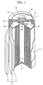
- Fig. 1 an example of the structure of the battery of the present invention is shown in Fig. 1, taking as an example the cylindrical nickel-metal hydride secondary battery for large current discharge.
- battery I is a battery which is characterized in that a W element and an Na element are present in the battery simultaneously.
- Battery II is a battery wherein at least W element is present in the battery and the below-mentioned conductive coating layer comprised mainly of an Na-containing cobalt compound is formed on the surface of the active material for positive electrode. In this battery II, it is preferred that an Na element coexists in the battery.
- battery III is a battery wherein at least W element is present in the battery and, as a separator, the below-mentioned separator is used. Also in this battery III, it is preferred that an Na element coexists in the battery.
- an electrode group 5 comprising a spirally wound sheet in which a positive electrode 2, a separator 3 and a negative electrode 4 are stacked on one another is accommodated, together with an alkali electrolyte liquid (not shown).
- the negative electrode 4 is arranged on the outermost of the electrode group, so that it is electrically contacted with the battery casing 1.
- the bottom portion of the electrode group 5 is welded, at the negative electrode 4 thereof, to a negative electrode current collector plate 9 arranged on the bottom of the battery casing. Further, the negative electrode current collector plate 9 is welded to the battery casing 1.
- an insulating gasket 8 in a ring form is arranged on the inner side of the upper opening of the battery casing 1, and a sealing plate 7 in a circular form having a pore 6 at the center thereof is arranged in a state such that the periphery portion of the sealing plate 7 is geared into the above insulating gasket 8.
- the sealing plate 7 air-tightly seals the upper opening of the battery casing 1 through the insulating gasket 8.
- a positive electrode current collector plate 14 having a pore 14a at the center thereof is welded and arranged, and further, on this positive electrode current collector plate 14, the positive electrode 2 in the electrode group 5 is welded.
- a positive electrode lead plate 15 is welded to the positive electrode current collector plate 14, and the other end of this positive electrode lead plate 15 is welded to the sealing plate 7.
- a safety valve 11 made of a rubber is arranged so that it closes the central pore 6 of the sealing plate 7, and further, a cap-like positive electrode terminal 10 is welded to the sealing plate 7 so as to cover the safety valve 11, so that the electrode group is sealed in.
- a press plate 12 which is made of an insulating material and has a central pore is arranged in a state such that only the above-mentioned positive electrode terminal 10 is penetrated through the above central pore, and an exterior tube 13 is arranged so as to cover the periphery portion of the press plate 12 and the side plane portion and bottom plane portion of the battery casing 1.
- the form of the battery is not limited to the cylindrical form mentioned above and, for example, may be a rectangular battery having a structure such that a nickel electrode, a separator and a negative electrode are stacked on one another to form an electrode group in a rectangular parallelepiped form, and the electrode group is accommodated in a rectangular battery casing and the casing is sealed up.
- battery I is characterized in that, in the battery assembled, a W element and an Na element are present simultaneously.
- the above-mentioned W element and Na element are present, mainly, in the alkali electrolyte liquid as a tungstic acid ion and a sodium ion, respectively.
- alkali electrolyte liquid used examples include, for example, a mixed aqueous solution of an aqueous sodium hydroxide solution and an aqueous lithium hydroxide solution, a mixed aqueous solution of an aqueous potassium hydroxide solution and an aqueous lithium hydroxide solution, and a mixed aqueous solution of an aqueous potassium hydroxide solution, an aqueous lithium hydroxide solution and an aqueous sodium hydroxide solution.
- the concentrations of the aqueous potassium hydroxide solution, the aqueous sodium hydroxide solution and the aqueous lithium hydroxide solution may be, respectively, 2.0 to 7.0 N, preferably 3.0 to 6.0 N; 1.0 to 6.0 N, preferably 2.0 to 5.0 N; and 0.3 to 2.0 N, preferably 0.5 to 1.5 N.
- the above-mentioned W element can be present in the battery by, for example, dissolving a W compound, such as WO 3 , H 2 WO 4 , K 2 WO 4 , Na 2 WO 4 ⁇ 2H 2 O or Li 2 WO 4 , in the alkali electrolyte liquid used in the assembling of the battery.
- a W compound such as WO 3 , H 2 WO 4 , K 2 WO 4 , Na 2 WO 4 ⁇ 2H 2 O or Li 2 WO 4
- the tungstic acid ion which is the state of the existing W element is adsorbed onto the positive electrode to form an electrochemically stable film covering the active material powder. Then, this film functions as a barrier against hydrogen which is generated in the standing or storage in a high temperature environment and the charging, so that the reduction of nickel oxyhydroxide in the positive electrode is suppressed, thus improving the self-discharge characteristics of the active material.
- the Na element can be present in the battery by adding sodium hydroxide to the alkali electrolyte liquid used in the assembling of the battery, or by preliminarily allowing the Na element to be carried on the positive electrode by adding sodium hydroxide to the alkali electrolyte liquid when the produced negative electrode is subjected to the below-mentioned alkali treatment.
- a binder for example, sodium polyacrylate is used in the production of the positive and negative electrodes, or when, for example, Na 2 WO 4 ⁇ 2H 2 O is dissolved in the alkali electrolyte liquid, the Na element can be present in the battery as a sodium ion.
- a part of the sodium ion which is the state of the existing Na element, penetrates into the crystal lattice of the active material for positive electrode in the course of the charge-discharge cycle of the battery to strain the crystal lattice, so that the penetration of the above-mentioned tungstic acid ion into the inner portion of the active material or the formation of the above-mentioned barrier film is promoted, thus exhibiting an effect of more effectively suppressing the self-discharge of the active material.
- the amount of the W element present in the battery and the amount of the Na element present in the battery satisfy the relationship represented by the above formulae (1) and (2).
- the x value representing the above-mentioned amount of the W element and the y value representing the above-mentioned amount of the Na element are defined as the values measured in accordance with the following procedure. An explanation on this is made below.
- the positive electrode and the negative electrode are dissolved in concentrated hydrochloric acid and the resultant solution is subjected to filtration.
- the resultant filtrate is subjected to inductively coupled plasma (ICP) emission spectrochemical analysis as such, to thereby quantitatively determine the W element.
- ICP inductively coupled plasma
- the residue obtained by the above filtration is incinerated, together with the filter paper, and then, subjected to alkali fusion and further dissolution in hydrochloric acid to give an aqueous solution, followed by the above ICP emission spectrochemical analysis.
- the same treatment is performed, followed by ICP emission spectrochemical analysis, to thereby quantitatively determine the W element.
- the value of the total W element amount quantitatively determined is divided by the quantitatively determined value of the alkali metal element obtained in (1) above, and the resultant value is multiplied by 100.
- the x value is 0.03 to 4.
- the x value is less than 0.03, the formation of the barrier film in an amount satisfactory for covering the surface of the active material powder does not proceed.
- the x value is more than 4, the adsorption of the tungstic acid ions onto the active material powder proceeds excessively, and thus, the reaction resistance between the positive electrode and the alkali electrolyte liquid is increased and the increase in viscosity makes the ion mobility low, so that the positive electrode capacity at which discharge can be conducted becomes small, thus preventing the increase of the capacity.
- Preferred x value is 0.1 to 2.
- the y value is selected so as to satisfy the relationship represented by the above formulae (1) and (2).
- the y value When the y value is less than 1.5, it becomes difficult to form the barrier film in an amount satisfactory for exhibiting the above-mentioned synergistic effect of the sodium ion and tungstic acid ion.
- the y value when the y value is more than -14x + 70, the penetration of the sodium ion into the active material proceeds excessively and the strain of the positive electrode becomes large, so that the formation of ⁇ -nickel oxyhydroxide is promoted, leading to lowering of both the utilization of the active material and the high rate discharge characteristics.
- the x value and the y value satisfy the relationship represented by the following formulae (3) and (4): 0.1 ⁇ x ⁇ 2 3 ⁇ y ⁇ -14x + 42
- the positive electrode 2 to be incorporated into the battery having the above-mentioned structure may be of either a sintering type or a paste type; however, the paste type is more effective for increasing the capacity of the battery because it is possible to support a large amount of the active material on the positive electrode.
- This paste type positive electrode is produced by a method in which a conductive material and a binder are incorporated into a powder comprised mainly of a nickel hydroxide powder, and the resultant mixture is mixed with an arbitrary solvent, such as water, to obtain a paste, and then, the obtained paste is applied onto and fills a conductive substrate, followed by drying and press molding.
- the value of a half width of the peak at (001) crystal face may be 0.8°/2 ⁇ (Cu-K ⁇ ) or more, especially preferably in the range of 0.9° to 1.1°/2 ⁇ (Cu-K ⁇ ), as measured by powdery X-ray diffraction analysis. This is because the charging efficiency of the battery assembled in a high temperature environment improves.
- nickel hydroxide used as the nickel hydroxide used, a eutectic of nickel hydroxide with one, or two or more of zinc, cobalt, bismuth and copper is preferred, and especially preferred is one containing zinc. This is because the charging efficiency improves, as compared to the case of the single nickel hydroxide.
- the lamellar structure of the nickel hydroxide is stabilized, so that the penetration of a large amount of the above-mentioned tungstic acid ion and sodium ion into the nickel hydroxide at the charging is prevented.
- the content of zinc in the nickel hydroxide is 3 to 10 % by weight.
- the zinc content is less than 3 % by weight, the crystal structure of nickel hydroxide is not stabilized.
- the zinc content is more than 10 % by weight, the relative content of the nickel hydroxide in the positive electrode becomes small, so that the capacity of the positive electrode is lowered.
- the content of Zn is more preferably 4 to 7 % by weight.
- the nickel hydroxide containing zinc can be prepared by, for example, a method in which nickel sulfate and a sulfate of zinc are dissolved in diluted sulfuric acid, and the resultant solution is added dropwise to an aqueous alkaline solution, to thereby effect a coprecipitation of hydroxides of nickel and zinc.
- the nickel hydroxide powder when the nickel hydroxide powder is too fine, even the central portion thereof becomes in the above-mentioned overcharge state at the charging, so that the entire powder is likely to be converted into ⁇ -nickel oxyhydroxide.
- the nickel hydroxide powder when the nickel hydroxide powder is too coarse, the difference in current collection efficiency between the central portion and the surface portion of the nickel hydroxide powder becomes too large, and thus, the overcharge state of the surface portion is selectively advanced and y-nickel oxyhydroxide is formed there, so that it is difficult to form a uniform ⁇ -nickel oxyhydoxide state. In any case, lowering in both the charging efficiency in a high temperature environment and capacity caused by the memory effects will be brought about.
- the active material powder comprised mainly of nickel hydroxide has preferably an average particle diameter of 3 to 20 ⁇ m, more preferably 8 to 14 ⁇ m.
- the surface of the powder comprised mainly of nickel hydroxide is coated with a conductive coating layer comprised mainly of an Na-containing cobalt compound.
- a conductive coating layer comprised mainly of an Na-containing cobalt compound.
- a mixed powder of a powder comprised mainly of nickel hydroxide and a powder of a metallic cobalt or a cobalt compound, such as cobalt hydroxide, tricobalt tetraoxide, dicobalt trioxide, cobalt monoxide or a mixture thereof.
- the content of the metallic cobalt or cobalt compound in the above powder is selected in the range of from 0.5 to 20 % by weight, based on the total weight of the powder.
- the content is less than 0.5 % by weight, the formation of the above-mentioned conductive matrix is unsatisfactory at the initial charge of the battery which has incorporated therein the positive electrode having carried thereon the obtained active material powder, so that the utilization of the active material does not become high.
- the content is more than 20 % by weight, the relative content of the nickel hydroxide powder in the active material becomes small, so that the discharge capacity of the battery is lowered.
- the content of the metallic cobalt or cobalt compound is preferably 1.0 to 12 % by weight.
- the above-mentioned powder is placed in a vessel equipped with a stirrer to form a mixing and stirring system, and an aqueous alkaline solution is sprayed thereto or added thereto dropwise while stirring the powder, so that the content of the vessel is uniformly mixed, simultaneously with heating the mixing and stirring system in the coexistence with oxygen.
- aqueous alkaline solution an aqueous solution of sodium hydroxide is used, and further, a mixture obtained by mixing into the aqueous solution of sodium hydroxide an aqueous solution of potassium hydroxide and an aqueous solution of lithium hydroxide may be used.
- a part of the cobalt compound contained in the powder is dissolved in the aqueous alkaline solution as complex ions, and the complex ions are distributed between the powder in a state such that they covers the surface of the powder, so that a precursor of the above-mentioned conductive matrix is formed.
- the sodium ions in the aqueous sodium hydroxide solution used are distributed on the surface of the powder in a state such that they are incorporated into the formed precursor of the conductive matrix.
- the concentration of the aqueous alkaline solution is selected in the range of from 1 to 14 N.
- the concentration is lower than 1 N, the metallic cobalt or cobalt compound contained in the powder is difficult to be dissolved in the aqueous alkaline solution, and thus, the formation of the above-mentioned precursor of the conductive matrix does not satisfactorily proceed, making it difficult to increase the utilization of the active material.
- the concentration is higher than 14 N, the viscosity of the above aqueous alkaline solution increases, and thus, it becomes difficult to satisfactorily wet the powder, so that the metallic cobalt or cobalt compound cannot be dissolved satisfactorily.
- the method for heating there is no particular limitation, for example, there can be mentioned a method of subjecting the mixing and stirring system to external heating, a method of allowing a heated air to directly blow the mixing and stirring system, and a method of subjecting the mixing and stirring system to irradiation of a microwave from a magnetron.
- the microwave irradiation is advantageously employed.
- the microwave by using the microwave, the water molecules which incorporate therein and coexist with the above-mentioned powder are vibrated, so that the powder is uniformly heated. Therefore, the precursor of the conductive matrix formed on the surface of the powder is oxidized also in a state of being heated uniformly, and as a result, on the surface of the powder, as a conductive coating layer, a conductive matrix comprising a higher order oxide of cobalt is uniformly formed.
- this microwave irradiation also has an effect for causing a defect in the crystal structure of the nickel hydroxide powder and changing the state of pores by the energy applied so as to increase the surface activity of the nickel hydroxide powder after the treatment.
- the above-mentioned heat treatment using a microwave may be performed for the mixing and stirring system for about 10 minutes.
- the temperature of the heat treatment for the mixing and stirring system is 35 to 160°C.
- the temperature is lower than 35°C, the amount of the metallic cobalt or cobalt compound which is contained in the powder dissolved in the aqueous alkaline solution is lowered, and thus, the formation of the above-mentioned precursor of the conductive matrix is unsatisfactory, so that the utilization of the active material does not become high very much.
- the temperature is higher than 160°C, the nickel hydroxide powder per se begins to suffer structural changing, so that the powder as an active material is deteriorated.
- the surface of the powder comprised mainly of nickel hydroxide is coated with a conductive coating layer comprising a higher order oxide of cobalt containing Na (conductive matrix).
- the Na contained in the above conductive matrix functions as a component contributing to the improvement of the conductivity of this conductive matrix, simultaneously with functioning as a component contributing to the suppression of the self-discharge of the active material in association with the above-mentioned alkali electrolyte liquid.
- the content of this Na is 0.05 to 5 % by weight, based on the weight of the active material powder produced.
- the Na content is less than 0.05 % by weight, the effect for the improvement of the conductivity of the conductive coating layer formed is unsatisfactory, so that the utilization of the active material powder is lowered.
- the Na content is more than 5 % by weight, not only does the effect for the improvement of the conductivity of the conductive coating layer reach saturation, but also the preparation of the mixture paste for the positive electrode becomes difficult since the paste is strongly alkaline during the mixing of the mixture paste for the positive electrode with water, so that the positive electrode production is more difficult.
- Preferred Na content is selected in the range of 0.2 to 1 % by weight, based on the weight of the active material powder produced.
- binders used in the production of the positive electrode include, for example, carboxymethyl cellulose, methyl cellulose, sodium polyacrylate and polytetrafluoroethylene.
- current collectors to be filled with the paste include, for example, three-dimensional substrates, such as a foamed nickel substrate and a felt plated substrate which is obtained by subjecting a substrate or nonwoven fabric of a network sintered metal fiber to nickel plating; and two-dimensional substrates, such as a punched metal and an expanded metal.
- separator there is no particular limitation on the separator, and those which have conventionally been used may be used as such, and, of these, preferred is a sheet-form member containing a polyolefin fiber and having an acid group introduced into the surface thereof.
- polyolefin fibers include a polyolefin fiber itself including a polyethylene fiber and a polypropylene fiber as preferred examples; a conjugate fiber having a core/shell configuration wherein the surface of a certain polyolefin fiber is coated with a different polyolefin fiber; and a conjugate fiber having a dividing configuration wherein different types of polyolefin fibers are joined together in a circular form.
- the sheet-form member there can be mentioned a nonwoven fabric and a woven fabric of the above-mentioned various polyolefin fibers, and a composite sheet obtained by the combination of the above nonwoven fabric and woven fabric.
- the nonwoven fabric can be produced by, for example, a dry method, a wet method, a spunbond method and a melt-blow method.
- the average fiber diameter is 0.5 to 40 ⁇ m.
- the average fiber diameter is smaller than 0.5 ⁇ m, the mechanical strength required for the separator is lowered, and, for example, the separator may be damaged during the production of an electrode group.
- the average fiber diameter is larger than 40 ⁇ m, it becomes impossible to satisfactorily coat the surfaces of the positive electrode and the negative electrode which face to each other, causing that a short-circuiting between the positive and negative electrodes frequently occurs through the spaces between the fibers.
- the thickness of the sheet-form member is preferably 0.1 to 0.3 mm, especially preferably 0.10 to 0.2 mm.
- the unit weight of the sheet-form member is 30 to 80 g/m 2 .
- the unit weight is less than 30 g/m 2 , the strength required for the separator tends to lower.
- the unit weight is more than 80 g/m 2 , the battery capacity tends to lower. Therefore, it is more preferred that the unit weight is selected in the range of 40 to 70 g/m 2 .
- the acid group introduced into the sheet-form member there is no particular limitation as long as it has a high hydrophilicity.
- the acid group is introduced into the surface of the sheet-form member by introducing a substance containing the acid group into the surface of the fiber constituting the sheet-form member.
- substances containing a carboxyl group include acrylic acid, methacrylic acid and esters thereof; substances having a functional group capable of directly reacting to an acid or a base to form a salt, such as vinyl pyridine, vinyl pyrrolidone, styrene sulfonic acid, and styrene; and substances having a functional group capable of graft-copolymerizing and then undergoing hydrolysis to form a salt.
- a sheet-form member for introducing an acid group into a sheet-form member using acrylic acid, a sheet-form member is immersed in an aqueous solution of acrylic acid, and then removed.
- the sheet-form member is, for example, subjected to irradiation of ultraviolet rays, so that the acrylic acid monomer is graft-copolymerized on the fiber constituting the sheet-form member, thus introducing thereinto a carboxylic group as an acid group.
- a method for introducing a sulfonic group there can be mentioned a method in which a sheet-form member is immersed in fuming sulfuric acid.
- the acid group introduced into the surface of the separator is present in the state of an anion in the alkali electrolyte liquid, such as -COO - .
- a tungstic acid ion is also present in the state of an anion in the alkali electrolyte liquid.
- the tungstic acid ion in the alkali electrolyte liquid is inhibited from being adsorbed to the separator due to the repellency against the acid group on the surface of the separator.
- the tungstic acid ion is likely to present near the surface of the positive electrode in a high concentration, and thus, the oxygen generation overpotential on the surface of the positive electrode becomes high, so that the charging efficiency is improved even in a high temperature environment.
- the amount of the acid group introduced which exhibits the above-mentioned effects can be represented by the potassium ion-exchange capacity (milli-equivalent per gramme: meq/g), and this amount is preferably 0.05 to 2.0 meq per 1 g of the separator.
- the potassium ion-exchange capacity is less than 0.05 meq/g, it becomes impossible to allow the tungstic acid ion in the alkali electrolyte liquid to be present near the surface of the positive electrode in a high concentration, so that the charging efficiency at a high temperature is not improved well.
- the potassium ion-exchange capacity is more than 2 meq/g, the operation voltage disadvantageously becomes low when the large current discharge is conducted.
- Preferred potassium ion-exchange capacity is 0.1 to 1.8 meq/g.
- the above-mentioned potassium ion-exchange capacity means the value obtained by the following titration method.
- Negative electrode 4 is produced by a method in which a powder of a hydrogen storage alloy, a binder and, if desired, a conductive material such as graphite or carbon black, in predetermined amounts are mixed with water to prepare a paste, and the paste is applied onto and fills a conductive substrate, followed by drying and molding.
- the hydrogen storage alloy used there is no particular limitation, as long as it can have occluded therein hydrogen which is electrochemically generated in an alkali electrolyte liquid and easily desorb the occluded hydrogen when a discharge is conducted.
- a multiple element system metal alloy such as LaNi 5 , MmNi 5 (Mm means a Mischmetal), LmNi 5 (Lm means a Mischmetal having lanthanum enriched) or alloys obtained by substituting a part of Ni by Al, Mn, Co, Ti, Cu, Zn, Zr, Cr, B or like; a TiNi system metal alloy, a TiFe system metal alloy, a MgNi system metal alloy or the combination thereof; a metal alloy having a composition represented by LnNi w Co x Mn y Al z (wherein Ln represents at least one selected from Y and rare earth elements, and w, x, y and z individually represents atomic ratios satisfying
- the hydrogen storage alloy represented by the formula: LmNi x Al y A z (wherein Lm represents a Mischmetal having lanthanum enriched; A represents at least one selected from Al and Co; and x, y and z individually represents atomic ratios satisfying 4.8 ⁇ x+y+z ⁇ 5.4 ) is preferred because the fine powder formation during the charge-discharge cycle is suppressed, and hence, it is possible to improve the cycle life property of the battery.
- the above powder of a hydrogen storage alloy is obtained by subjecting the hydrogen storage alloy having the above-mentioned composition to, for example, mechanical grinding or hydrogenation powderization.
- the alloy powder obtained has a specific surface area of 0.05 to 0.2 m 2 /g.
- the alloy powder is powder (A) which is obtained by a method in which the ingot of the hydrogen storage alloy is subjected to hydrogenation powderization once under conditions wherein the temperature is 2 to 30°C and the hydrogen pressure is 5 to 10 atom, and has a specific surface area of 0.05 to 0.2 m 2 /g as measured by a BET method, or powder (B) which is obtained by a method in which the ingot of the hydrogen storage alloy is subjected to hydrogenation powderization once under the above-mentioned conditions, to thereby obtain a ground ingot having a specific surface area of 0.05 to 0.2 m 2 /g as measured by a BET method, and the obtained ground ingot is further ground.
- the specific surface area may fall outside of the range of 0.05 to 0.2 m 2 /g as measured by a BET method.
- the above-mentioned specific surface area is a factor of ensuring the area for the reaction of the hydrogen storage alloy with the alkali electrolyte liquid.
- the larger the specific surface area the faster the electrode reaction. Therefore, a large current discharge can be achieved, and the low-temperature discharge characteristics are improved.
- this specific surface area becomes too large, the corrosion of the hydrogen storage alloy caused by the alkali electrolyte liquid proceeds even if the composition of the alkali electrolyte liquid is specified, so that the amount of the alkali electrolyte liquid consumed increases, leading to shortening of the charge-discharge cycle life of the battery.
- preferred specific surface area of the hydrogen storage alloy used is selected in the range of 0.05 to 0.2 m 2 /g.
- the hydrogen storage alloy used is preferably subjected to the following surface treatment.
- a surface treatment such as plating with a metal including nickel or a metal oxide having a corrosion resistance, immersion to an alkali electrolyte liquid, a heat treatment, or a fluorine treatment.
- Such surface treatments may be conducted for either the alloy powder before producing the negative electrode or the produced negative electrode.
- the hydrogen storage alloy contains a component which can be easily dissolved in the alkali electrolyte liquid, such as a Mn component, among the above surface treatments, it is preferred to employ the treatment of the immersion to an aqueous alkaline solution.
- the component present on the surface of the hydrogen storage alloy which can be easily dissolved in the alkali electrolyte liquid including a Mn component as a representative example, is preliminarily dissolved and removed, and thus, the surface activity of the hydrogen storage alloy is increased.
- aqueous alkaline solution for example, one, or two or more of an aqueous solution of sodium hydroxide, an aqueous solution of potassium hydroxide and an aqueous solution of lithium hydroxide can be used.
- the concentration of the aqueous alkaline solution is 4N to 9N.
- the concentration of the aqueous alkaline solution used is 6N to 8N.
- binder used in the production of the negative electrode there can be mentioned the above-mentioned polymer materials used in the production of positive electrode 2.
- the current collector there can be mentioned, for example, two-dimensional substrates, such as a punched metal, an expanded metal, a perforated steel plate and a nickel net; and substrates having a three-dimensional network structure, such a felt-like porous metal and a spongy metal substrate.
- the separator Between the above-described positive electrode and negative electrode is disposed the separator, to thereby produce an electrode group.
- the electrode group is accommodated in a battery casing, and the above-mentioned alkali electrolyte liquid is charged thereinto, and then, the battery casing is sealed up, to thereby assemble the nickel-metal hydride secondary battery of the present invention.
- the amount of the alkali electrolyte liquid charged is selected in the range of 0.7 to 1.7 cm 3 /Ah relative to the theoretical capacity (unit: Ah) of the positive electrode incorporated.
- the nickel-metal hydride secondary battery has a structure such that an electrode group and an alkali electrolyte liquid are accommodated in a battery casing having a determined volume. Therefore, the volume of the electrode group and the amount of the alkali electrolyte liquid are restricted by the volume of the battery casing. Further, when the amount of the alkali electrolyte liquid charged relative to the theoretical capacity of the positive electrode is higher than 1.7 cm 3 /Ah, the volume of the electrode group accommodated cannot be satisfactorily increased due to the excess amount of the alkali electrolyte liquid charged, so that it is difficult to increase the capacity of the battery satisfactorily.
- the charged amount is selected in the range of 1.7 cm 3 /Ah or less, and as a result, the increase of the battery capacity is achieved.
- the charged amount is less than 0.7 cm 3 /Ah, the amount of the alkali electrolyte liquid required for the electrode reaction is lack, so that the ion mobility in the positive electrode is lowered, leading to lowering of the utilization of the active material for positive electrode.
- Preferred amount of the alkali electrolyte liquid charged is 0.9 to 1.5 cm 3 /Ah.
- Nickel sulfate, cobalt sulfate and zinc sulfate were dissolved in diluted sulfuric acid, and the pH of the resultant acidic solution was adjusted using an aqueous potassium hydroxide solution and an aqueous ammonia, to thereby prepare a precipitate of nickel hydroxide containing cobalt and zinc. This precipitate was separated by filtration and dried, to thereby obtain a nickel hydroxide powder having a particle diameter of 0.1 to 20 ⁇ m.
- a nickel fiber substrate was filled with the obtained paste, followed by drying and press molding, to thereby produce a positive electrode.
- the amount of the filling paste was adjusted so that the capacity density of the positive electrode became 20 mAh/cm 2 .
- the obtained paste was applied to a nickel punched metal (opening ratio: 45 %) and dried, followed by roll milling, to thereby produce an electrode of the hydrogen storage alloy (negative electrode).
- This separator has an average fiber diameter of 10 ⁇ m and a unit weight of 60 g/m 2 .
- the separator was disposed between the above-mentioned positive electrode and negative electrode, and the whole of these materials was spirally wound, to thereby obtain an electrode group, and the electrode group was accommodated in a battery casing simultaneously with charging thereinto 2.8 ml of the alkali electrolyte liquid, followed by sealing up of the casing, to thereby assemble a nickel-metal hydride secondary battery (rated capacity: 1700 mAh) having a size of 4/5A and a structure shown in Fig. 1.
- batteries were assembled in substantially the same manner as in the above Examples except that Na 2 MoO 4 ⁇ 2H 2 O was used instead of Na 2 WO 4 ⁇ 2H 2 O and H 2 WO 4 , and the characteristics were shown in Tables 2 to 4 as Comparative Examples 19 to 21.
- K concentration (ppm) Na concentration (ppm) Li concentration (ppm) Standard solution 1 0.5 1.0 2.0 Standard solution 2 0.5 1.0 2.0 Standard solution 3 0.2 0.4 0.8
- the measurement wavelengths used for K, Na and Li were 766.5 nm, 589.0 nm and 670.8 nm, respectively.
- each of the batteries which have been subjected to the measurements of the battery characteristics mentioned in item 4 above was dismounted, so that the positive electrode, the negative electrode and the separator were removed.
- the positive electrode and negative electrode were dissolved in about 60% nitric acid, and the separator was also treated with about 60% nitric acid so that the substances adhering thereto were dissolved, followed by combination of these solutions, to thereby obtain a sample solution.
- each of the batteries which have been subjected to the measurements of the battery characteristics was dismounted, so that the positive electrode, the negative electrode and the separator were removed.
- the positive electrode and negative electrode were dissolved in 35 % by weight concentrated hydrochloric acid, and then, the resultant solution was subjected to filtration.
- the resultant filtrate was subjected to ICP emission spectrochemical analysis as such using the above-mentioned ICP emission spectrochemical analysis apparatus under the same conditions, so that W was quantitatively determined using the above-prepared calibration curve.
- the determined value is referred to as w 1 (ppm).
- the residue obtained by the above filtration was incinerated, together with the filter paper, and the resultant ash was subjected to alkali fusion using 10 parts by weight of sodium carbonate and 20 parts by weight of boric acid into a glass form, and further added thereto water, concentrated hydrochloric acid (35 % by weight) and 10 % tartaric acid, to thereby effect a complete fusion.
- the resultant solution was subjected to ICP emission spectrochemical analysis using the above-mentioned ICP emission spectrochemical analysis apparatus under the same conditions, and W was quantitatively determined using the calibration curve. The determined value is referred to as w 2 (ppm).
- W was quantitatively determined by performing ICP emission spectrochemical analysis. The determined value is referred to as w 3 (ppm).
- a nonwoven fabric made of a polypropylene fiber (average fiber diameter: 8 ⁇ m) which was produced by spunbond method and has a unit weight of 60 g/m 2 and a thickness of 0.20 mm was provided.
- this nonwoven fabric was immersed in an aqueous solution of acrylic acid and then removed.
- the surface of the nonwoven fabric was subjected to irradiation of ultraviolet rays, to thereby effect a graft-polymerization of an acrylic acid monomer.
- the fabric was washed with water so as to remove the unreacted acrylic acid.
- the amounts of the acrylic acid monomer introduced were changed so that the resultant separators have the potassium ion-exchanged capacity values on the surface thereof shown in Table 5. These separators are referred to as separator I.
- the above-mentioned nonwoven fabric was immersed in fuming sulfuric acid and removed, and then washed with water, to thereby effect a sulfonation treatment.
- the amounts of the sulfonic group introduced were changed so that the resultant separators have the potassium ion-exchanged capacity values shown in Tables 6 and 7. These separators are referred to as separator II.
- a charging was conducted at a temperature of 25 °C at 0.1 C for 15 hours, and subsequently, a discharging was conducted at a temperature of 25 °C at 0.2 C until the voltage of the battery became 1 V.
- a discharge capacity (C 0 ) was measured.
- a charging was conducted at a temperature of 50 °C at 0.1 C for 15 hours, and subsequently, the temperature was lowered to 25 °C, and after the battery temperature was confirmed to be consistent with the ambient atmosphere temperature, a discharging was conducted at 0.2 C until the voltage of the battery became 1 V.
- a discharge capacity (C M ) was measured. Then, a calculation was made on the formula: C M x 100/C 0 , to thereby determine a value of the high temperature charging efficiency (%).
- a charging was conducted at a temperature of 25 °C at 0.1 C for 15 hours, and subsequently, a discharging was conducted at a temperature of 25 °C at 0.2 C until the voltage of the battery became 1 V.
- a discharge capacity (C 0 ) was measured.
- a charging was conducted at a temperature of 25 °C at 0.1 C for 15 hours, and subsequently, a discharging was conducted at a temperature of 25 °C at 2 C until the voltage of the battery became 1 V.
- a discharge capacity (C 1 ) was measured.
- a calculation was made on the formula: C 1 x 100/C 0 , to thereby determine a value of the large current discharge ratio (%).
- the amount of the W element (x value) present in the battery was measured in the same manner as in Examples 1 to 41.
- LiOH were dissolved KOH and NaOH so that the total alkali concentration of the resultant solution became 8 N, to thereby prepare a mixed aqueous solution, and in the mixed aqueous solution were Na 2 WO 4 ⁇ 2H 2 O and H 2 WO 4 in various amount ratios, to thereby prepare various alkali electrolyte liquids.
- Example 2 using the positive electrode and the negative electrode used in Example 1, between these electrodes was disposed the separator shown in Table 8, to thereby produce an electrode group. And the electrode group was accommodated in a battery casing together with 2.8 ml of the above-mentioned alkali electrolyte liquid, to thereby assemble a battery shown in Fig. 1.
- battery III is a battery which exhibits not only excellent self-discharge characteristics in a high temperature storage as well as excellent high temperature charging efficiency, but also excellent large current discharge ratio.
- Nickel sulfate, cobalt sulfate and zinc sulfate were dissolved in diluted sulfuric acid, and the pH of the resultant solution was adjusted using an aqueous solution of potassium hydroxide and an aqueous ammonia, to thereby prepare a precipitate of nickel hydroxide containing cobalt and zinc. This precipitate was separated by filtration and dried, to thereby obtain a nickel hydroxide powder containing Zn and Co and having an average particle diameter of 10 ⁇ m.
- Nickel-plated porous substrates each having a porosity of 95 % and a thickness of 1.7 mm were individually filled with the above-obtained pastes, followed by drying and press molding, to thereby produce various positive electrodes.
- the amount of the filling paste was adjusted so that the capacity density of the positive electrode became 20 mAh/cm 2 .
- a hydrogen storage alloy having a composition: LmNi 0.4 Co 0.4 Mn 0.3 Al 0.3 was subjected to mechanical grinding, to thereby obtain a 200 mesh-pass (Tyler mesh) powder.
- the obtained paste was applied to a nickel punched metal (opening ratio: 45%) and dried, followed by roll milling, to thereby produce an electrode of the hydrogen storage alloy (negative electrode).
- a separator obtained by graft-polymerizing acrylic acid on a nonwoven fabric mainly made of a polypropylene fiber was disposed between the above-mentioned positive electrode and negative electrode, and the whole of these materials was spirally wound, to thereby obtain an electrode group.
- the electrode group was accommodated in a battery casing simultaneously with charging thereinto 2.8 ml of the above-mentioned alkali electrolyte liquid, followed by sealing up of the casing, to thereby assemble a nickel-metal hydride secondary battery having a size of 4/5A and a structure shown in Fig. 1.
- Utilization (%) (Discharge capacity measured/Theoretical capacity of active material) x 100
- Capacity maintaining ratio (%) (Discharge capacity measured/Discharge capacity after the 1st cycle) x 100.
- Active material powders were prepared in substantially the same procedure as in Examples 100 to 107 except that the amount of the cobalt monoxide added was changed to 0.5 part by weight, and batteries were assembled in the same manner. With respect to these batteries, the characteristics and the x values are shown in Table 10.
- Example 108 0.05 0.03 94 85 90
- Example 109 5.0 0.03 95 86 91
- Example 110 0.5 1.0 97 90 93
- Example 111 3.0 1.0 95 88 93
- Example 112 0.5 2.0 97 89 92
- Example 113 3.0 2.0 95 87 92
- Example 114 0.05 4.0 93
- Active material powders were prepared in substantially the same procedure as in Examples 100 to 107 except that the amount of the cobalt monoxide added was changed to 20 part by weight, and batteries were assembled in the same manner. With respect to these batteries, the characteristics and the x values are shown in Table 11.
- Active material powders were prepared in substantially the same procedure as in Example 102 except that the amount of the cobalt monoxide added was changed to 0.3 part by weight and 21 parts by weight, respectively, and batteries were assembled in the same manner. With respect to these batteries, the characteristics and the x values are shown in Table 12.
- the amount of cobalt monoxide added is selected in the range of 0.5 to 20 % by weight.
- Nickel hydroxide powders having the values of half width of the peak at (101) crystal face as measured by powdery X-ray diffraction analysis shown in Table 13 were provided.
- a nickel fiber substrate was filled with the obtained paste, followed by drying and press molding, to thereby produce a positive electrode.
- a hydrogen storage alloy having a composition: LmNi 0.4 Co 0.4 Mn 0.3 Al 0.3 was treated by a high-frequency furnace into an ingot, and the ingot was subjected to hydrogenation powderization once under conditions wherein the temperature was 2 to 30 °C and the hydrogen pressure was 5 to 10 atom, to thereby obtain five types of alloy ingot powders having specific surface areas, as measured by a BET method, of 0.02 m 2 /g (alloy powder 1), 0.05 m 2 /g (alloy powder 2), 0.10 m 2 /g (alloy powder 3), 0.15 m 2 /g (alloy powder 4) and 0.23 m 2 /g (alloy powder 5). Further, these powders were subjected to mechanical grinding, to thereby obtain alloy powders.
- the specific surface area was measured by Quantasorb QS-20 (trade name), manufactured and sold by Quantachrome.
- the obtained pastes were individually applied to a nickel punched metal (opening ratio: 45 %) and dried, followed by roll milling, to thereby produce five types electrodes of the hydrogen storage alloy (negative electrodes).
- a hydrophilicity-treated nonwoven fabric made of a polyolefin was disposed between the above-mentioned each positive electrode and each negative electrode, and the whole of these materials was spirally wound, to thereby obtain an electrode group. Then, the electrode group was accommodated in a battery casing.
- each of the negative electrodes used in Examples 129 to 134, Examples 137 to 139 and Comparative Example 61 was subjected to immersion treatment in a heated aqueous solution of sodium hydroxide having a concentration of 30 % by weight at a temperature of 80 °C for 1 hour.
- Each of the prepared alkali electrolyte liquids (temperature: 25 °C) was charged so that the capacity became 1.3 cm 3 /Ah relative to the theoretical capacity of the positive electrode, to thereby assemble a cylindrical nickel-metal hydride secondary battery (size: 4/5A; rated capacity: 1,700 mAh) having a structure shown in Fig. 1.
- Example 129 In the production of the battery in Example 129, the amount of the alkali electrolyte liquid charged was reduced to 1.1 cm 3 /Ah, and the volume of the positive electrode accommodated was increased so as to make up for the reduced amount of the alkali electrolyte liquid, to thereby assemble a battery.
- the capacity became 1,830 mAh, that is, 8 % larger than the capacity in Example 129. It is noted that the levels of the characteristics of this battery were similar to those in Example 129.
- Nickel sulfate, cobalt sulfate and zinc sulfate were dissolved in diluted sulfuric acid, and the pH of the resultant acidic solution was adjusted using an aqueous solution of potassium hydroxide and an aqueous ammonia, to thereby prepare a precipitate of nickel hydroxide containing cobalt and zinc. This precipitate was separated by filtration and dried, to thereby obtain a nickel hydroxide powder.
- a nickel fiber substrate was filled with the obtained paste, followed by drying and press molding, to thereby produce a positive electrode.
- the amount of the filling paste was adjusted so that the capacity density of the positive electrode became 20 mAh/cm 2 .
- a hydrogen storage alloy having a composition: LmNi 0.4 Co 0.4 Mn 0.3 Al 0.3 was subjected to mechanical grinding, to thereby obtain a 200 mesh-pass (Tyler mesh) powder.
- the obtained paste was applied to a nickel punched metal (opening ratio: 45%) and dried, followed by roll milling, to thereby produce an electrode of the hydrogen storage alloy (negative electrode).
- a separator obtained by graft-polymerizing acrylic acid on a nonwoven fabric mainly made of a polypropylene fiber was disposed between the above-mentioned positive electrode and negative electrode, to thereby obtain an electrode group.
- the electrode group was accommodated in a battery casing.
- the charge-discharge cycle wherein the -10 mV cut-charging was conducted was repeated in fifty cycles, and the discharge capacity after discharging until the voltage became 1.1 V from the full charging stage was determined.
- the determined value was referred to as after-cycle capacity.
- the battery was subjected to complete discharge at 1 C until the voltage became 1 V, and then, the environmental temperature was increased to 60 °C, and after the battery temperature was confirmed to be consistent with the environmental temperature, the -10 mV cut-charging was conducted at 1 C, and then, a discharging was conducted at 1 C until the voltage of the battery became 1 V.
- the capacity at this point in time was referred to as 60 °C capacity.
- High temperature charging efficiency (%) (60 °C capacity/Initial capacity) x 100.
- each of the batteries which have been subjected to the measurements of the battery characteristics was dismounted, and the positive electrode was ground by a grinder and the nickel substrate was completely removed therefrom by a magnet, so that only the active material powder was separate.
- the x value for the W element present in the battery was measured in the same manner as in Example 1.
- Example 141 10.0 0.03 3.0 98 90 85
- Example 142 10.0 0.03 10.0 100 92 88
- Example 143 10.0 0.03 20.0 98 93 86
- Example 144 10.0 1.0 3.0 99 93 87
- Example 145 10.0 1.0 10.0 101 95
- Example 146 10.0 1.0 20.0 99 94
- Example 148 10.0 4.0 10.0 98 93 91
- Example 149 10.0 4.0 20.0 96 94 89
- Example 151 10.0 0.02 3.0 98 82 77
- Example 152 10.0 0.02 10.0 100 84 80
- Example 153 10.0 0.02 20.0 98 85 78
- Example 154 10.0 0.0 0.02 0.02 98 85
- the average particle diameter of the active material is selected in the range of 3 to 20 ⁇ m.
- the nickel-metal hydride secondary battery of the present invention exhibits high utilization of the active material and is unlikely to undergo self-discharge in a high temperature storage. Therefore, this battery is advantageous not only in that it exhibits excellent self-discharge characteristics and high capacity maintaining rate at a high temperature and can be charged at a high efficiency in a high temperature environment, and further has the above excellent characteristics in combination, but also in that it can exhibit a large current discharge. Accordingly, the nickel-metal hydride secondary battery of the present invention is greatly commercially advantageous as a driving power source in various electronic appliances, electric vehicles and the like, which are used in various temperature environments.
Landscapes
- Chemical & Material Sciences (AREA)
- Chemical Kinetics & Catalysis (AREA)
- Electrochemistry (AREA)
- General Chemical & Material Sciences (AREA)
- Engineering & Computer Science (AREA)
- Manufacturing & Machinery (AREA)
- Composite Materials (AREA)
- Inorganic Chemistry (AREA)
- Secondary Cells (AREA)
- Battery Electrode And Active Subsutance (AREA)
Applications Claiming Priority (8)
| Application Number | Priority Date | Filing Date | Title |
|---|---|---|---|
| JP4941299 | 1999-02-26 | ||
| JP4941299 | 1999-02-26 | ||
| JP23845899 | 1999-08-25 | ||
| JP23845899 | 1999-08-25 | ||
| JP33327699 | 1999-11-24 | ||
| JP33327699 | 1999-11-24 | ||
| JP2000032149 | 2000-02-09 | ||
| JP2000032149A JP2001217000A (ja) | 1999-02-26 | 2000-02-09 | ニッケル・水素二次電池 |
Publications (2)
| Publication Number | Publication Date |
|---|---|
| EP1032067A2 true EP1032067A2 (de) | 2000-08-30 |
| EP1032067A3 EP1032067A3 (de) | 2002-03-13 |
Family
ID=27462350
Family Applications (1)
| Application Number | Title | Priority Date | Filing Date |
|---|---|---|---|
| EP00103378A Withdrawn EP1032067A3 (de) | 1999-02-26 | 2000-02-23 | Nickel-metalhydrid Sekundärbatterie |
Country Status (5)
| Country | Link |
|---|---|
| US (1) | US6399247B1 (de) |
| EP (1) | EP1032067A3 (de) |
| JP (1) | JP2001217000A (de) |
| CN (1) | CN1159793C (de) |
| TW (1) | TW492206B (de) |
Cited By (3)
| Publication number | Priority date | Publication date | Assignee | Title |
|---|---|---|---|---|
| EP1271677A1 (de) * | 2001-06-21 | 2003-01-02 | Matsushita Electric Industrial Co., Ltd. | Elektrode aus Wasserstoff absorbierender Legierung |
| EP1229598A3 (de) * | 2001-02-05 | 2005-04-13 | Sanyo Electric Co., Ltd. | Gesinterte Nickelelektrode für alkalische Speicherbatterie, Verfahren zu ihrer Herstellung und alkalische Speicherbatterie |
| EP2234189A1 (de) * | 2009-03-26 | 2010-09-29 | Sanyo Electric Co., Ltd. | Alkalibatterien-Speichersystem mit partiellem Laden und Entladen |
Families Citing this family (42)
| Publication number | Priority date | Publication date | Assignee | Title |
|---|---|---|---|---|
| US6680144B2 (en) * | 1999-10-29 | 2004-01-20 | Kvg Technologies, Inc. | Battery separator |
| JP4212213B2 (ja) * | 2000-03-23 | 2009-01-21 | 三洋電機株式会社 | アルカリ蓄電池およびその製造方法 |
| JP4322472B2 (ja) * | 2002-05-31 | 2009-09-02 | 東芝電池株式会社 | 密閉型ニッケル亜鉛一次電池 |
| US7238446B2 (en) * | 2002-12-24 | 2007-07-03 | Ovonic Battery Company, Inc. | Active electrode composition with conductive polymeric binder |
| US7261970B2 (en) * | 2004-04-23 | 2007-08-28 | Ovonic Battery Company Inc. | Nickel metal hydride battery design |
| JP4872189B2 (ja) * | 2004-06-02 | 2012-02-08 | 株式会社豊田中央研究所 | アルカリ蓄電池 |
| CN100369305C (zh) | 2004-12-30 | 2008-02-13 | 比亚迪股份有限公司 | 一种燃料电池 |
| CN102160220B (zh) * | 2008-07-28 | 2014-08-13 | S·E·斯鲁普 | 循环利用具有碱性电解质的电池 |
| US20110033769A1 (en) * | 2009-08-10 | 2011-02-10 | Kevin Huang | Electrical Storage Device Including Oxide-ion Battery Cell Bank and Module Configurations |
| US20110038100A1 (en) * | 2009-08-11 | 2011-02-17 | Chun Lu | Porous Carbon Oxide Nanocomposite Electrodes for High Energy Density Supercapacitors |
| US9325036B2 (en) | 2010-04-19 | 2016-04-26 | Siemens Aktiengesellschaft | Molten salt-containing metal electrode for rechargeable oxide-ion battery cells operating below 800°C |
| US8338025B2 (en) | 2010-08-09 | 2012-12-25 | Siemens Aktiengesellschaft | Self-sealed metal electrode for rechargeable oxide-ion battery cells |
| US20120058396A1 (en) | 2010-09-07 | 2012-03-08 | Chun Lu | Oxidation-resistant metal supported rechargeable oxide-ion battery cells and methods to produce the same |
| CN101950818A (zh) * | 2010-09-20 | 2011-01-19 | 四川宝生新能源电池有限公司 | 高温镍氢电池 |
| US20120129058A1 (en) | 2010-11-24 | 2012-05-24 | Litzinger Kevin P | Electrical Energy Storage Device |
| US9054366B2 (en) | 2010-11-24 | 2015-06-09 | Siemens Aktiengesellschaft | Electrical energy storage device |
| JP2012212648A (ja) * | 2011-03-24 | 2012-11-01 | Tokyo Univ Of Science | ナトリウム二次電池用電極およびナトリウム二次電池 |
| US8911895B2 (en) | 2011-04-21 | 2014-12-16 | Siemens Aktiengesellschaft | All solid state rechargeable oxide-ion battery (ROB) system |
| US9023529B2 (en) * | 2011-05-18 | 2015-05-05 | Battelle Memorial Institute | Nanomaterials for sodium-ion batteries |
| US8894722B2 (en) | 2011-06-24 | 2014-11-25 | Siemens Aktiengesellschaft | Construction of planar rechargeable oxide-ion battery cells and stacks using stainless steel housing structures |
| US20130115528A1 (en) | 2011-11-04 | 2013-05-09 | Chun Lu | Rechargeable anion battery cell using a molten salt electrolyte |
| US9627728B2 (en) | 2011-11-04 | 2017-04-18 | Siemens Aktiengesellschaft | Rechargeable anion battery cell using a molten salt electrolyte |
| CN102496745A (zh) * | 2011-11-28 | 2012-06-13 | 泉州劲鑫电子有限公司 | 一种高温镍氢电池及其制作方法 |
| JP2013114888A (ja) * | 2011-11-29 | 2013-06-10 | Sanyo Electric Co Ltd | アルカリ蓄電及びこのアルカリ蓄電池を用いたアルカリ蓄電池システム |
| US8685288B2 (en) | 2012-01-10 | 2014-04-01 | Siemens Aktiengesellschaft | Solid-solution method for producing iron-containing active materials for rechargeable oxide-ion battery cells |
| JP5853799B2 (ja) * | 2012-03-22 | 2016-02-09 | 三洋電機株式会社 | アルカリ蓄電池 |
| CN102610866A (zh) * | 2012-03-30 | 2012-07-25 | 广州市云通磁电有限公司 | 一种镍基碱性动力电池专用电解液的制备方法 |
| WO2014050074A1 (ja) * | 2012-09-25 | 2014-04-03 | 三洋電機株式会社 | アルカリ蓄電池及びそれを用いた蓄電池システム。 |
| US20140106242A1 (en) | 2012-10-15 | 2014-04-17 | Charles R. Osborne | Oxygen plenum configurations of components in low cost planar rechargeable oxide-ion battery (rob) cells and stacks |
| JP6200897B2 (ja) * | 2012-10-30 | 2017-09-20 | 三洋電機株式会社 | 蓄電池モジュール及び蓄電池システム |
| JP6225116B2 (ja) * | 2012-10-30 | 2017-11-01 | 三洋電機株式会社 | 蓄電池システム |
| JPWO2014068868A1 (ja) * | 2012-10-30 | 2016-09-08 | 三洋電機株式会社 | ニッケル水素蓄電池及び蓄電池システム |
| CN102956892B (zh) * | 2012-11-01 | 2015-04-22 | 浙江天能能源科技有限公司 | 一种高温镍氢电池及其制备方法 |
| WO2014124288A1 (en) | 2013-02-09 | 2014-08-14 | The George Washington University | Molten air rechargeable batteries |
| US20140242476A1 (en) | 2013-02-28 | 2014-08-28 | Michael Kühne | Operating battery stack system performance by alternating the flow of heat carrying fluid used therein |
| JP6232722B2 (ja) * | 2013-03-25 | 2017-11-22 | 三洋電機株式会社 | ニッケル−カドミウム蓄電池 |
| JP2015032358A (ja) * | 2013-07-31 | 2015-02-16 | プライムアースEvエナジー株式会社 | ニッケル水素蓄電池 |
| JP7093286B2 (ja) * | 2018-10-30 | 2022-06-29 | 株式会社豊田自動織機 | ニッケル金属水素化物電池 |
| WO2020090175A1 (ja) * | 2018-10-30 | 2020-05-07 | 株式会社豊田自動織機 | ニッケル金属水素化物電池 |
| CN109888411B (zh) * | 2019-04-09 | 2022-03-11 | 南开大学 | 一种大倍率、长循环、宽温区水系钠离子全电池 |
| JP7120979B2 (ja) * | 2019-09-30 | 2022-08-17 | プライムアースEvエナジー株式会社 | ニッケル水素二次電池及びニッケル水素二次電池の製造方法 |
| JP7236413B2 (ja) * | 2020-08-21 | 2023-03-09 | プライムアースEvエナジー株式会社 | ニッケル水素蓄電池及びニッケル水素蓄電池の製造方法 |
Family Cites Families (19)
| Publication number | Priority date | Publication date | Assignee | Title |
|---|---|---|---|---|
| JPS50132441A (de) | 1974-04-08 | 1975-10-20 | ||
| JPH0630251B2 (ja) | 1985-11-01 | 1994-04-20 | 三洋電機株式会社 | ニツケル−水素二次電池 |
| NL8901776A (nl) * | 1989-07-11 | 1991-02-01 | Philips Nv | Elektrochemische cel. |
| JP2682162B2 (ja) | 1989-08-22 | 1997-11-26 | 株式会社ユアサコーポレーション | アルカリ蓄電池用ニッケル電極活物質 |
| JPH05289992A (ja) | 1992-04-09 | 1993-11-05 | Casio Comput Co Ltd | 売上データ処理システム |
| US5506069A (en) * | 1993-10-14 | 1996-04-09 | Ovonic Battery Company, Inc. | Electrochemical hydrogen storage alloys and batteries fabricated from Mg containing base alloys |
| US5501917A (en) * | 1994-01-28 | 1996-03-26 | Hong; Kuochih | Hydrogen storage material and nickel hydride batteries using same |
| JP3247800B2 (ja) | 1994-06-21 | 2002-01-21 | 日立工機株式会社 | 外装式カーボンブラシの共回り防止装置 |
| JP3393944B2 (ja) | 1995-01-10 | 2003-04-07 | 日立マクセル株式会社 | 水素化物二次電池 |
| JP3512128B2 (ja) | 1995-02-15 | 2004-03-29 | 日立マクセル株式会社 | アルカリ蓄電池およびその製造方法 |
| JP3454627B2 (ja) | 1996-02-06 | 2003-10-06 | 三洋電機株式会社 | アルカリ蓄電池用正極活物質の製造方法及びアルカリ蓄電池 |
| JPH1063142A (ja) | 1996-08-23 | 1998-03-06 | Ricoh Co Ltd | 画像形成装置 |
| JP3910664B2 (ja) | 1996-08-27 | 2007-04-25 | 株式会社東芝 | ニッケル水素二次電池 |
| JPH10106559A (ja) | 1996-09-30 | 1998-04-24 | Sanyo Electric Co Ltd | アルカリ蓄電池用ニッケル極 |
| JPH10172558A (ja) | 1996-12-09 | 1998-06-26 | Hitachi Maxell Ltd | 水素化物二次電池 |
| DE69707637T2 (de) * | 1996-12-20 | 2002-08-01 | Matsushita Electric Industrial Co., Ltd. | Sekundärbatterie mit nichtwässerigem Elektrolyt |
| EP0851515A3 (de) * | 1996-12-27 | 2004-10-27 | Canon Kabushiki Kaisha | Pulvermaterial, Elektrode, Sekundärzelle und Verfahren zur Herstellung |
| JPH10241643A (ja) | 1997-02-25 | 1998-09-11 | Hitachi Maxell Ltd | 水素化物二次電池 |
| JP3661045B2 (ja) * | 1997-05-30 | 2005-06-15 | 松下電器産業株式会社 | アルカリ蓄電池 |
-
2000
- 2000-02-09 JP JP2000032149A patent/JP2001217000A/ja active Pending
- 2000-02-23 EP EP00103378A patent/EP1032067A3/de not_active Withdrawn
- 2000-02-25 TW TW089103529A patent/TW492206B/zh not_active IP Right Cessation
- 2000-02-25 US US09/513,890 patent/US6399247B1/en not_active Expired - Fee Related
- 2000-02-25 CN CNB001083864A patent/CN1159793C/zh not_active Expired - Fee Related
Cited By (5)
| Publication number | Priority date | Publication date | Assignee | Title |
|---|---|---|---|---|
| EP1229598A3 (de) * | 2001-02-05 | 2005-04-13 | Sanyo Electric Co., Ltd. | Gesinterte Nickelelektrode für alkalische Speicherbatterie, Verfahren zu ihrer Herstellung und alkalische Speicherbatterie |
| US6946222B2 (en) | 2001-02-05 | 2005-09-20 | Sanyo Electric Co., Ltd. | Sintered nickel electrode for alkaline storage battery, method of forming the same, and alkaline storage battery |
| EP1271677A1 (de) * | 2001-06-21 | 2003-01-02 | Matsushita Electric Industrial Co., Ltd. | Elektrode aus Wasserstoff absorbierender Legierung |
| US7943255B2 (en) | 2001-06-21 | 2011-05-17 | Panasonic Corporation | Hydrogen-absorption alloy electrode |
| EP2234189A1 (de) * | 2009-03-26 | 2010-09-29 | Sanyo Electric Co., Ltd. | Alkalibatterien-Speichersystem mit partiellem Laden und Entladen |
Also Published As
| Publication number | Publication date |
|---|---|
| CN1159793C (zh) | 2004-07-28 |
| JP2001217000A (ja) | 2001-08-10 |
| TW492206B (en) | 2002-06-21 |
| EP1032067A3 (de) | 2002-03-13 |
| CN1268782A (zh) | 2000-10-04 |
| US6399247B1 (en) | 2002-06-04 |
Similar Documents
| Publication | Publication Date | Title |
|---|---|---|
| US6399247B1 (en) | Nickel-metal hydride secondary battery | |
| JP3558590B2 (ja) | アルカリ蓄電池用正極活物質の製造方法 | |
| US5965295A (en) | Alkaline secondary battery, paste type positive electrode for alkaline secondary battery, method for manufacturing alkaline secondary battery | |
| EP0680107A1 (de) | Nickelwasserstoff Sekundärbatterie | |
| EP0999602A2 (de) | Batterieseparator und Herstellungsverfahren und alkalische Sekundärbatterie mit inkorporiertem Separator | |
| US20020172758A1 (en) | Alkaline storage battery | |
| US6156456A (en) | Positive electrode active material for alkaline storage battery | |
| JP2012188728A (ja) | 複合水素吸蔵合金及びニッケル水素蓄電池 | |
| US6528209B2 (en) | Active material for positive electrode for alkaline secondary cell and method for producing the same, and alkaline secondary cell using the active material for positive electrode and method for producing the same | |
| JP3400927B2 (ja) | アルカリ二次電池用正極の製造方法 | |
| JP7732751B2 (ja) | 鉄-炭素複合材料、その製造方法、負極およびニッケル水素電池 | |
| JP4128635B2 (ja) | ニッケル水素蓄電池の製造方法 | |
| JP2001126722A (ja) | 鉄複合酸化物電極およびこれを用いたアルカリ電池 | |
| JP3393978B2 (ja) | アルカリ二次電池 | |
| JP2000138050A (ja) | ニッケル・水素二次電池 | |
| JP3151379B2 (ja) | アルカリ二次電池の製造方法 | |
| JP3343470B2 (ja) | アルカリ二次電池の製造方法 | |
| JP2001283843A (ja) | アルカリ蓄電池用正極材料およびアルカリ蓄電池 | |
| JP3686316B2 (ja) | アルカリ二次電池 | |
| JP3352347B2 (ja) | アルカリ二次電池 | |
| JPH09213325A (ja) | アルカリ二次電池 | |
| JPH103940A (ja) | ニッケル−金属水素化物蓄電池及びその製造方法 | |
| JP2001176505A (ja) | 電極及びアルカリ二次電池 | |
| JP2001256948A (ja) | ニッケル・水素二次電池 | |
| JP2001148237A (ja) | ニッケル・水素二次電池 |
Legal Events
| Date | Code | Title | Description |
|---|---|---|---|
| PUAI | Public reference made under article 153(3) epc to a published international application that has entered the european phase |
Free format text: ORIGINAL CODE: 0009012 |
|
| 17P | Request for examination filed |
Effective date: 20000330 |
|
| AK | Designated contracting states |
Kind code of ref document: A2 Designated state(s): DE FR GB |
|
| AX | Request for extension of the european patent |
Free format text: AL;LT;LV;MK;RO;SI |
|
| PUAL | Search report despatched |
Free format text: ORIGINAL CODE: 0009013 |
|
| AK | Designated contracting states |
Kind code of ref document: A3 Designated state(s): DE FR GB |
|
| AX | Request for extension of the european patent |
Free format text: AL;LT;LV;MK;RO;SI |
|
| AKX | Designation fees paid |
Free format text: DE FR GB |
|
| 17Q | First examination report despatched |
Effective date: 20090422 |
|
| STAA | Information on the status of an ep patent application or granted ep patent |
Free format text: STATUS: THE APPLICATION IS DEEMED TO BE WITHDRAWN |
|
| 18D | Application deemed to be withdrawn |
Effective date: 20090903 |