EP1032093A1 - Pressluftgetriebener Crimphandapparat - Google Patents
Pressluftgetriebener Crimphandapparat Download PDFInfo
- Publication number
- EP1032093A1 EP1032093A1 EP00301341A EP00301341A EP1032093A1 EP 1032093 A1 EP1032093 A1 EP 1032093A1 EP 00301341 A EP00301341 A EP 00301341A EP 00301341 A EP00301341 A EP 00301341A EP 1032093 A1 EP1032093 A1 EP 1032093A1
- Authority
- EP
- European Patent Office
- Prior art keywords
- crimping
- housing
- linkage
- members
- dies
- Prior art date
- Legal status (The legal status is an assumption and is not a legal conclusion. Google has not performed a legal analysis and makes no representation as to the accuracy of the status listed.)
- Withdrawn
Links
- 238000002788 crimping Methods 0.000 title claims abstract description 170
- 238000012544 monitoring process Methods 0.000 claims abstract description 28
- 230000000903 blocking effect Effects 0.000 claims abstract description 19
- 230000033001 locomotion Effects 0.000 claims abstract description 17
- 210000002445 nipple Anatomy 0.000 claims description 12
- 230000000994 depressogenic effect Effects 0.000 claims description 5
- 208000012880 Finger injury Diseases 0.000 claims 3
- 230000000712 assembly Effects 0.000 abstract description 3
- 238000000429 assembly Methods 0.000 abstract description 3
- 230000006835 compression Effects 0.000 abstract description 3
- 238000007906 compression Methods 0.000 abstract description 3
- 238000009413 insulation Methods 0.000 abstract description 2
- 230000026058 directional locomotion Effects 0.000 abstract 1
- 230000014759 maintenance of location Effects 0.000 abstract 1
- 210000003811 finger Anatomy 0.000 description 37
- 238000003780 insertion Methods 0.000 description 4
- 230000037431 insertion Effects 0.000 description 4
- 239000012212 insulator Substances 0.000 description 3
- 210000003813 thumb Anatomy 0.000 description 3
- 230000000694 effects Effects 0.000 description 2
- 210000004247 hand Anatomy 0.000 description 2
- 239000004020 conductor Substances 0.000 description 1
- 230000000881 depressing effect Effects 0.000 description 1
- 238000009434 installation Methods 0.000 description 1
- 238000004519 manufacturing process Methods 0.000 description 1
- 238000007789 sealing Methods 0.000 description 1
Images





Classifications
-
- H—ELECTRICITY
- H01—ELECTRIC ELEMENTS
- H01R—ELECTRICALLY-CONDUCTIVE CONNECTIONS; STRUCTURAL ASSOCIATIONS OF A PLURALITY OF MUTUALLY-INSULATED ELECTRICAL CONNECTING ELEMENTS; COUPLING DEVICES; CURRENT COLLECTORS
- H01R43/00—Apparatus or processes specially adapted for manufacturing, assembling, maintaining, or repairing of line connectors or current collectors or for joining electric conductors
- H01R43/04—Apparatus or processes specially adapted for manufacturing, assembling, maintaining, or repairing of line connectors or current collectors or for joining electric conductors for forming connections by deformation, e.g. crimping tool
- H01R43/042—Hand tools for crimping
- H01R43/0427—Hand tools for crimping fluid actuated hand crimping tools
-
- Y—GENERAL TAGGING OF NEW TECHNOLOGICAL DEVELOPMENTS; GENERAL TAGGING OF CROSS-SECTIONAL TECHNOLOGIES SPANNING OVER SEVERAL SECTIONS OF THE IPC; TECHNICAL SUBJECTS COVERED BY FORMER USPC CROSS-REFERENCE ART COLLECTIONS [XRACs] AND DIGESTS
- Y10—TECHNICAL SUBJECTS COVERED BY FORMER USPC
- Y10T—TECHNICAL SUBJECTS COVERED BY FORMER US CLASSIFICATION
- Y10T29/00—Metal working
- Y10T29/53—Means to assemble or disassemble
- Y10T29/5313—Means to assemble electrical device
- Y10T29/532—Conductor
- Y10T29/53209—Terminal or connector
- Y10T29/53213—Assembled to wire-type conductor
- Y10T29/53222—Means comprising hand-manipulatable implement
- Y10T29/53226—Fastening by deformation
Definitions
- the present invention relates to a hand held compressed air powered crimping tool for securing ring tongue terminals to stripped electrical wire ends, and securing butt splices to join two electrical wire ends.
- AMP Incorporated and other companies do provide portable crimping apparatus for crimping electrical terminals onto conductors, and these portable products are selectively powered by hydraulic actuators, compressed air actuators, and/or electric motors, each requiring an external power source.
- the "T" head arrangement of the crimping dies is not known to have been incorporated into these portable products.
- this hand held compressed air powered crimping tool is provided to operators, who will at first use their hands and fingers to pre-position in a "T" heads, the members to be crimped. Then, after this pre-positioning is completed, an operator whose fingers cannot then re-enter the motion path of the dies, will depress and pivot the cleared trigger to open an air valve to utilize the flow of compressed air into a pneumatic actuator, which moves the crimping linkage to complete the crimping motions of the dies; and the members are then fully crimped together.
- the operator is not able to move the trigger until a safety linkage, interrelated with the overall crimping linkage, has a portion thereof, i.e. a blocking member, moved out of the way of depending portions of the trigger, during the closing moments of the finger force movements of the overall crimping linkage.
- the operator Via the operation of a monitoring linkage, which is also interrelated with the overall crimping linkage, the operator is able to ascertain when the finger force movements of the overall crimping linkage are sufficiently completed to firmly hold in place the members, to be subsequently crimped together, when the compressed air power is applied to the overall crimping linkage.
- the monitoring linkage during the powered crimping operational period, prevents the reversal of movements of components of the overall crimping linkage. Then, when the powered crimping operational period is fully completed, and the members are successfully crimped together, the monitoring linkage then has been moved to clear the way for the reversal of motion of the overall crimping linkage. The reversal occurs under the force of a compression spring, to separate the crimping dies in the "T" head for the convenient removal of the members that are well crimped together
- respective insertion stops are in position in the "T" head locale to stop the insertion of the ring tongue terminals at a pre-designated location.
- the respective insertion stops are quickly and conveniently moved out of the way.
- the balance of the components of the crimping tool are all positioned within a two piece rectangular essentially hollow housing having positioners, linkage guiding groves, and openings to receive fasteners, portions of the trigger mechanism, and rotational shafts of the crimping linkage.
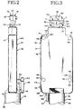
- a hand held compressed air powered crimping tool in accordance with a preferred embodiment of the present invention which utilizes the "T" head arrangements of spaced sets of respective matched crimping dies of different set sizes, is illustrated in the drawings, wherein:
- the hand held compressed air powered crimping tool 20 is illustrated in a preferred embodiment in drawings.
- this crimping tool 20 includes the well known and utilized "T" head assembly 22, which positions two spaced sets 24, 26 of dies of respective matching sizes of upper dies 28 and lower dies 30.
- These "T" head assemblies 22 were and are being used in hand held crimping tools that are completely manipulated by the hands and fingers of the operators. They are useful in securing members, such as ring tongue terminals 32 to stripped electrical wire ends 34 and also to secure butt splices that join together two electrical wire ends, along with their respective insulators 36.
- this crimping tool 20 may be used by operators. They may conveniently hold, manipulate, and operate this crimping tool 20 with less effort while creating the better crimping of the members to complete electrical circuits and/or to complete circuit connections to electrical equipment. Very importantly, the operators, who utilize this crimping tool 20 know their fingers will not be injured by the crimping dies, when the pressurized air power is being utilized to crimp the members together.
- the cylindrical exterior of the cylinder 38 of the compressed air actuator 40 is extendably positioned from a hollow housing 42 to serve as a handle 44.
- a handle 44 When an operator's hand is placed about the handle 44, his or her thumb or finger is conveniently positioned to depress the pivotal trigger 46, which contacts a valve stem 48 of a compressed air valve 50 positioned in the hollow housing 42.
- This pivotal trigger 46 cannot be depressed until a depending potion or potions thereof, such as depending pins 52, can enter into the hollow housing 42.
- Pin receiving volumes 54, 56, in the hollow housing 42 are obstructed by a blocking member 58 of a safety linkage 60, arranged in the hollow housing 42 and interconnected with the crimping linkage 62, which, is also arranged in the hollow housing 42.
- the "T" head assembly 22 is finger manipulated to be closed about the members to be crimped.
- both the crimping linkage 62, and the safety linkage 60 have been sufficiently moved by the operator's finger forces, so the blocking member 58 of the safety linkage 60, clears the pin receiving volumes 54,56, in the hollow housing 42.
- the trigger 46 is pivotable to open the air valve 50 and undertake the compressed air powered crimping of the members to be crimped, and the operator has her or his fingers out of the way of the closing upper and lower dies 28, 30.
- a monitoring linkage 66 is arranged within the hollow housing 42 to serve the operator by letting her or him know the members to be crimped are fully pre-positioned, by their finger manipulations, between the dies, which are then closed so the operator will not later have his or her fingers injured, when the compressed air power is utilized during the crimping of the members.
- the monitoring linkage assembly 68 serves to keep its monitoring linkage 66, the safety linkage 60 and the crimping linkage 62, from returning to their starting open die positions of the "T" head assembly 22, until the full compressed air powered crimping cycle has been completed, thereby, insuring a successful crimping of the members has been undertaken.
- the "T” head assembly 22 used in this hand held compressed air powered crimping tool 20 is similar to those "T" head assemblies used in the finger and hand completely manipulated crimping tools.
- the "T” head assembly 22 has two “T” sections 72, 74, joined by respective fastener 70, 71, with like entries to receive other components of the "T” head, and with holes to receive a fastener to join them to a crimping actuator.
- the support members 76 or the leg members 76 of each "T" section 72, 74 which depend from the top portions 78 of each "T” section 72, 74, are slidably positioned in the hollow housing 42, in respect to part of their lengths.
- an upper insert 84 having the spaced upper dies 28 is adjustably positioned in respective entries 80, 82, of the "T" sections 72, 74.
- An adjustment cam pin 86 passes through hole 88 in "T” section 72, then through a hole 92 in the upper insert 84, and thereafter through a like hole 88 in the other "T” section 74.
- the pointing member 87 thereof is moved, to one of four selectable positions, indicating the simultaneously movement of the upper dies 28, via the movement of the upper insert 84, into a selected one of four respective spaced locations from lower dies 30.
- the lower dies 30 are pin 94 positioned and held in an overall entry 96 of the hollow housing 42.
- the lower dies 30 are arranged respective sections 98, 102, 104, and 106.
- the upper and lower dies 28, 30, are arranged in spaced apart sets 24, 26, and each set is of a different size. The operator then, at any one operational time has two sets of dies of respective sizes to be selected for use in crimping members together.
- the "T" head assembly 22 is preferably arranged to include two alike adjustable stops 100, one for each set of dies 24, 26.
- Each stop 100 has a depending elongated pin receiving entry 101.
- a member to be crimped such as the ring tongue terminal 32
- an adjustable stop 100 in their in use position, is moved to contact an adjustable stop 100, in the same way pre-positioning of all the members to be crimped.
- each adjustable stop 100 is moved clear of the members to be crimped, via the clearance provided in the depending elongated receiving entry 101.
- the hollow housing 42 is preferably rectangular in its overall configuration and made in two pieces 108, 110.
- One piece 108 is made to have a larger receiving volume 112 to receive and to position the components of the crimping linkage 62, the safety linkage 60, and the monitoring linkage assembly 68.
- Also partially positioned within this larger receiving volume 112 are portions of the "T" head, and portions of the compressed air, i.e. pneumatic, actuator 40.
- clearance volumes 114 not specifically formed, receive, at selected compressed air power operational times, the depending pins 52 of trigger 46, which pass through respective holes 116 in this housing piece 108.
- the larger receiving volume 112 piece 108 of the hollow housing 42 includes a groove 118 to slidably receive and guide portions of the crimping linkage 62 and the safety linkage 60. Also this piece 108 includes a threaded entry 122 for securing the pneumatic actuator 40.
- an opening 124 is provided for an air nipple connector 126, for connection to an airline 127 an opening 128 for an air valve 50, two openings 132 to receive mounting pins 134 to pivotally position left and right pivotal lever arms 136, 138, of the crimping linkage 62, and openings 142 to receive fasteners 144 that hold the pieces 108, 110, of the hollow housing together.
- the piece 108 of the hollow housing 42 also has internal compressed air passageways 146 to direct compressed air from the air nipple connector 126 to the air valve 50, then to the compressed air, i.e. pneumatic actuator 40.
- the crimping linkage 62 is connected between the "T" head assembly 22 and the compressed air, i.e. pneumatic, actuator 40 and operationally mounted within the hollow housing 42.
- the crimping linkage 62 is illustrated in the starting positions. During this starting time the members to be crimped together and being positioned between a set 24 or 26 of the dies, and the "T" head assembly is initially moved by finger applied force to move dies into firm contact with the members to be crimped. Under their finger applied force, the crimping linkage 62 in part, moves a distance, to also move the safety linkage 60, so the blocking member 58 clears away from the path of the depending pins 52 of the trigger 46.
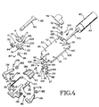
- the several components of the crimping linkage 62 are also illustrated in figures 4 and 13, and in respect to these several components, they are:
- This arrangement of the crimping linkage 62 when moved by the compressed air force, via the pneumatic actuator 40, creates a better and stronger crimping force applied, via the offset pawls 174, 176, of the left and right pivotal arms 136, 138, secured to the spaced apart links 148, 152, inturn secured to the "T" head assembly 22.
- the Pneumatic Actuator i.e. The Compressed Air Actuator
- the pneumatic actuator 40 also referred to as the compressed air actuator 40, has an end 188 with threads 192 and an "O" ring 194 for threadably securing and sealing the end 188 in the threaded entry 122 of the hollow housing 42.
- the remaining portions of the pneumatic actuator 40 being cylindrical in shape, serve as the handle 44 of the crimping tool 20.
- a rod 190 extending from a piston, not shown, of the pneumatic actuator 40, movably extends into hollow housing 42 and is threadably attached to the movable spreader 186 of the crimping linkage 62.
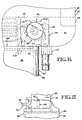
- the compressed air guiding and controlling arrangement 196 is illustrated in Figures 14 and 15. This arrangement 196 has:
- the finger depressible trigger 46 is pivotally secured to piece 108 of the hollow housing 42, by a hinge arrangement 214.
- Two depending pins 52 are attached to the finger contacting potion 216 of the trigger 46. They are arranged to pass through respective entries 116 and into the pin receiving volumes 54, 56, in the hollow housing 42, when a blocking member 58 of a safety linkage 60 has been moved clear of the entries 116 of the pin receiving volumes 54, 56.
- the safety linkage 60 and its effective use is illustrated in Figures 1, 4, 5, 6, 7, 9, 10, 11, and 13.
- the safety linkage 60 is interconnected with the crimping linkage 62, by in effect being an integral extension 222 of link 152 of the two spaced apart links 148, 152, of the crimping linkage 62, as particularly shown in Figure 13.
- a blocking member 58 of the safety linkage 60 is obstructing the entries 218 in the hollow housing 42, preventing the depending pins 52 of the trigger 46 from entering receiving volumes 54, 56, in the hollow housing 42.
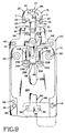
- the operator of this hand held crimping tool 20 is using his or her fingers, both to position the members to be crimped and also to move the set 24 or 26 of the dies together to preliminary bear against the members to be crimped, as shown in Figure 10.
- the crimping linkage 62 and the safety linkage 60 have moved sufficiently, so the blocking member 58 clears the entries 218 in the hollow housing 42, as illustrated in Figure 10.
- a monitoring linkage assembly 68 inclusive of a monitoring linkage 66, is utilized in respect to three functions.
- this assembly 68 is used to monitor the adequate finger forced moment of a set 24 or 26 of the dies about members to be crimped to keep them in their intended pre-positioning arrangement, while awaiting the utilization of the compressed air power.
- this assembly 68 is used to monitor the adequate completion of the crimping of the members during the utilization of the compressed air power.
- this assembly 68 is then used to clear the way for the crimping linkage 62, the safety linkage 60, and its own monitoring linkage 66, to be returned to their starting positions, via the return force of the coiled spring 222.
- the coiled spring 222 is confined and guided by the movable spreader 186. Also, the coiled spring 222 extends between the end 188 of the rod 190 of the compressed air actuator 40, and the capped extending rod 218 having the cap 220, which directly contacts the coiled spring 222. The other end of the capped extending rod 218 directly contacts the roller bearings 166.
- the monitoring linkage assembly 68 is illustrated in part in Figures 8 and 13, and then as assembled and utilized in Figures 9, 10, and 11.
- the hollow interior 224 of piece 110, serving as a cover 110, of the hollow housing 42 is shown as having a recess portion 226 serving to guide a portion of the monitoring linkage 66 and to position other components of the monitoring linkage assembly 68.
- Figure 13 the assembly of some of the crimping linkage 62 components, the safety linkage 60, and some of the components of the monitoring linkage assembly 68, is illustrated.
- the link 148 is integrally extended creating an extension 228, and further formed to have respective opposite side located alike functioning cams 232.
- Each cam 232 has two sets of clearances 234, 236, and a set of opposite extending portions 238 with ratchet teeth 242 on one side located axially at a slightly different location, i.e. offset location, than the ratchet teeth 242 on other side. This positioning creates more ratcheting positions, when the members to be crimped, are being firmly gripped in a set 24, or 26 of the dies, so they will remain in position, awaiting the crimping under the force derived from utilizing compressed air.
- this extension 228, serving as a part of this monitor linkage assembly is positioned in the recess portion 226 of the cover 110, the cams 232 thereof are operationally interfitted with additional components of this assembly 68, which are particularly shown in figure 8. They are the spaced pivotal pawls 244 rotatably mounted on the hollow housing 42 and having extending portions 246 , which are able to movably contact the cams 232 and the ratchet teeth 242 thereof to create the monitoring effect during the finger applied forces used, when the members to be crimped are being positioned in the set 24 or 26 of the dies.
Landscapes
- Engineering & Computer Science (AREA)
- Manufacturing & Machinery (AREA)
- Manufacturing Of Electrical Connectors (AREA)
Applications Claiming Priority (2)
| Application Number | Priority Date | Filing Date | Title |
|---|---|---|---|
| US253975 | 1999-02-22 | ||
| US09/253,975 US6119502A (en) | 1999-02-22 | 1999-02-22 | Hand held compressed air powered crimping tool to secure ring tongue terminals to stripped electrical wire ends, and to secure butt splices to join two electrical wire ends |
Publications (1)
| Publication Number | Publication Date |
|---|---|
| EP1032093A1 true EP1032093A1 (de) | 2000-08-30 |
Family
ID=22962430
Family Applications (1)
| Application Number | Title | Priority Date | Filing Date |
|---|---|---|---|
| EP00301341A Withdrawn EP1032093A1 (de) | 1999-02-22 | 2000-02-21 | Pressluftgetriebener Crimphandapparat |
Country Status (2)
| Country | Link |
|---|---|
| US (1) | US6119502A (de) |
| EP (1) | EP1032093A1 (de) |
Cited By (1)
| Publication number | Priority date | Publication date | Assignee | Title |
|---|---|---|---|---|
| WO2010141072A3 (en) * | 2009-06-03 | 2011-06-23 | Tyco Electronics Corporation | Disabling device for a pressing tool |
Families Citing this family (6)
| Publication number | Priority date | Publication date | Assignee | Title |
|---|---|---|---|---|
| US7340936B2 (en) * | 2005-06-13 | 2008-03-11 | Shear Tech, Inc. | Handheld crimping tool and method of using same |
| US8191223B2 (en) * | 2009-03-17 | 2012-06-05 | Mobley Stephen J | Snowmobile track clipping tool |
| EP2378615A1 (de) * | 2010-04-13 | 2011-10-19 | Schleuniger Holding AG | Crimppresse |
| CN104466590B (zh) * | 2014-10-29 | 2016-09-07 | 国家电网公司 | 一种接地线操作杆气动操作端结构 |
| US10727637B2 (en) * | 2018-01-02 | 2020-07-28 | Jeffrey C. Lemke | Cutting fixture exhibiting ram actuated and multiplying lever force for removing such as an H-tap crimp from a utility power line |
| CN110103003A (zh) * | 2019-05-23 | 2019-08-09 | 天津泰威齿轮有限公司 | 一种高效压销子工装 |
Citations (1)
| Publication number | Priority date | Publication date | Assignee | Title |
|---|---|---|---|---|
| US5487297A (en) * | 1995-01-17 | 1996-01-30 | The Whitaker Corporation | Crimping tool having mechanism for selectively biasing crimping dies to open or closed position |
Family Cites Families (12)
| Publication number | Priority date | Publication date | Assignee | Title |
|---|---|---|---|---|
| CA494963A (en) * | 1953-08-04 | P. Dupre Henry | Pneumatic press | |
| US2892368A (en) * | 1956-05-01 | 1959-06-30 | Amp Inc | Crimping tool |
| US2947207A (en) * | 1956-11-23 | 1960-08-02 | Amp Inc | Hand crimping tool |
| US2931260A (en) * | 1959-03-02 | 1960-04-05 | J T Henry Mfg Company Inc | Crimper with full stroke compelling ratchet mechanism |
| US3293732A (en) * | 1959-04-13 | 1966-12-27 | Amp Inc | Hand tool for crimping electrical connectors |
| US3867754A (en) * | 1974-02-22 | 1975-02-25 | Amp Inc | Stripper crimper machine |
| US4774762A (en) * | 1987-04-10 | 1988-10-04 | Mcdonnell Douglas Corporation | Hand-held automatic power crimper |
| US5596800A (en) * | 1992-12-17 | 1997-01-28 | Cable Ready, Inc. | Crimping tool with ratchet mechanism |
| US5787754A (en) * | 1993-02-24 | 1998-08-04 | Carrion; Jose | Tool for compression of motor/generator windings |
| US5309751A (en) * | 1993-03-29 | 1994-05-10 | The Whitaker Corporation | Portable crimping tool |
| US5490406A (en) * | 1994-08-19 | 1996-02-13 | The Whitaker Corporation | Crimping tool having die bottoming monitor |
| US5509194A (en) * | 1995-01-17 | 1996-04-23 | The Whitaker Corporation | Power crimping tool for tape feed products |
-
1999
- 1999-02-22 US US09/253,975 patent/US6119502A/en not_active Expired - Lifetime
-
2000
- 2000-02-21 EP EP00301341A patent/EP1032093A1/de not_active Withdrawn
Patent Citations (1)
| Publication number | Priority date | Publication date | Assignee | Title |
|---|---|---|---|---|
| US5487297A (en) * | 1995-01-17 | 1996-01-30 | The Whitaker Corporation | Crimping tool having mechanism for selectively biasing crimping dies to open or closed position |
Non-Patent Citations (2)
| Title |
|---|
| "626 PNEUMATIC TOOL SYSTEM.", PNEUMATIC TOOL SYSTEM CATALOG, XX, XX, 1 January 1998 (1998-01-01), XX, pages 01 - 06., XP002139101 * |
| "PREMIUM CERTI-CRIMP HAND TOOLS.", PREMIUM CERTI-CRIMP HAND TOOLS CATALOG, XX, XX, 1 January 1998 (1998-01-01), XX, pages 01 - 04., XP002139102 * |
Cited By (3)
| Publication number | Priority date | Publication date | Assignee | Title |
|---|---|---|---|---|
| WO2010141072A3 (en) * | 2009-06-03 | 2011-06-23 | Tyco Electronics Corporation | Disabling device for a pressing tool |
| CN102458816A (zh) * | 2009-06-03 | 2012-05-16 | 泰科电子公司 | 用于挤压工具的禁用装置 |
| US8316763B2 (en) | 2009-06-03 | 2012-11-27 | Tyco Electronics Corporation | Disabling device for a pressing tool |
Also Published As
| Publication number | Publication date |
|---|---|
| US6119502A (en) | 2000-09-19 |
Similar Documents
| Publication | Publication Date | Title |
|---|---|---|
| US5267464A (en) | Pipe ring crimping tool | |
| US5593197A (en) | Spark plug wire puller | |
| RU2317190C2 (ru) | Электрогидравлическое обжимное устройство и способ его эксплуатации | |
| US6474130B2 (en) | Pliers for crimping work pieces | |
| EP2679189B1 (de) | Einteilige Griffanordnung | |
| US3710610A (en) | Wire terminal crimping tool | |
| AU2017441860B2 (en) | Electric tool | |
| US6119502A (en) | Hand held compressed air powered crimping tool to secure ring tongue terminals to stripped electrical wire ends, and to secure butt splices to join two electrical wire ends | |
| US7997116B2 (en) | Link for crimping tool | |
| WO2003008152A3 (en) | Adjustable pliers wrench | |
| US7210378B1 (en) | Chain pliers with wire stripper | |
| DE2924019A1 (de) | Vorrichtung zum greifen von gegenstaenden | |
| US6629443B2 (en) | Ergonomic crimping apparatus | |
| US5928022A (en) | Mechanically-assited clip device for use in testing electrical equipment | |
| US7874193B2 (en) | Crimping die and crimping tool | |
| US20040251105A1 (en) | Direction switch for hand tool and reversible gear wrench | |
| CN111497262A (zh) | 使模具轴向对齐的系统和方法 | |
| CA2476088A1 (en) | Actuation mechanism for a power tool | |
| US5680788A (en) | Power crimping tool having improved crimping mechanism for tape feed products | |
| US5509194A (en) | Power crimping tool for tape feed products | |
| US11235371B2 (en) | Clinching machine | |
| CA3173002A1 (en) | Hand pliers designed to carry out crimping, and hand pliers comprising a plier head | |
| US5138909A (en) | Hand-held, pneumatic wire stripping tool | |
| US6279432B1 (en) | Force multiplication hand tool | |
| US7174813B2 (en) | Adjustable wrench |
Legal Events
| Date | Code | Title | Description |
|---|---|---|---|
| PUAI | Public reference made under article 153(3) epc to a published international application that has entered the european phase |
Free format text: ORIGINAL CODE: 0009012 |
|
| AK | Designated contracting states |
Kind code of ref document: A1 Designated state(s): DE FR GB IT |
|
| AX | Request for extension of the european patent |
Free format text: AL;LT;LV;MK;RO;SI |
|
| 17P | Request for examination filed |
Effective date: 20001013 |
|
| AKX | Designation fees paid |
Free format text: DE FR GB IT |
|
| 17Q | First examination report despatched |
Effective date: 20030303 |
|
| STAA | Information on the status of an ep patent application or granted ep patent |
Free format text: STATUS: THE APPLICATION IS DEEMED TO BE WITHDRAWN |
|
| 18D | Application deemed to be withdrawn |
Effective date: 20030714 |