EP1032095A2 - Méthode et appareil pour usiner et tordre un paire de conducteurs - Google Patents
Méthode et appareil pour usiner et tordre un paire de conducteurs Download PDFInfo
- Publication number
- EP1032095A2 EP1032095A2 EP00102946A EP00102946A EP1032095A2 EP 1032095 A2 EP1032095 A2 EP 1032095A2 EP 00102946 A EP00102946 A EP 00102946A EP 00102946 A EP00102946 A EP 00102946A EP 1032095 A2 EP1032095 A2 EP 1032095A2
- Authority
- EP
- European Patent Office
- Prior art keywords
- pair
- conductors
- twisting
- conductor
- processing
- Prior art date
- Legal status (The legal status is an assumption and is not a legal conclusion. Google has not performed a legal analysis and makes no representation as to the accuracy of the status listed.)
- Granted
Links
- 239000004020 conductor Substances 0.000 title claims abstract description 120
- 238000012545 processing Methods 0.000 title claims abstract description 19
- 238000000034 method Methods 0.000 title claims description 7
- 238000012546 transfer Methods 0.000 claims abstract description 18
- 238000004519 manufacturing process Methods 0.000 claims description 7
- 230000008569 process Effects 0.000 claims description 3
- 238000003860 storage Methods 0.000 abstract description 2
- 238000002788 crimping Methods 0.000 description 9
- 230000005540 biological transmission Effects 0.000 description 1
- 230000008878 coupling Effects 0.000 description 1
- 238000010168 coupling process Methods 0.000 description 1
- 238000005859 coupling reaction Methods 0.000 description 1
- 238000005520 cutting process Methods 0.000 description 1
- 238000011161 development Methods 0.000 description 1
- 230000018109 developmental process Effects 0.000 description 1
- 238000006073 displacement reaction Methods 0.000 description 1
- 238000009413 insulation Methods 0.000 description 1
- 238000003754 machining Methods 0.000 description 1
- 238000004806 packaging method and process Methods 0.000 description 1
- 238000012856 packing Methods 0.000 description 1
- 230000001105 regulatory effect Effects 0.000 description 1
- 238000007789 sealing Methods 0.000 description 1
- 238000000926 separation method Methods 0.000 description 1
- 238000004904 shortening Methods 0.000 description 1
Images


Classifications
-
- H—ELECTRICITY
- H01—ELECTRIC ELEMENTS
- H01B—CABLES; CONDUCTORS; INSULATORS; SELECTION OF MATERIALS FOR THEIR CONDUCTIVE, INSULATING OR DIELECTRIC PROPERTIES
- H01B13/00—Apparatus or processes specially adapted for manufacturing conductors or cables
- H01B13/02—Stranding-up
- H01B13/0207—Details; Auxiliary devices
-
- H—ELECTRICITY
- H01—ELECTRIC ELEMENTS
- H01R—ELECTRICALLY-CONDUCTIVE CONNECTIONS; STRUCTURAL ASSOCIATIONS OF A PLURALITY OF MUTUALLY-INSULATED ELECTRICAL CONNECTING ELEMENTS; COUPLING DEVICES; CURRENT COLLECTORS
- H01R43/00—Apparatus or processes specially adapted for manufacturing, assembling, maintaining, or repairing of line connectors or current collectors or for joining electric conductors
- H01R43/28—Apparatus or processes specially adapted for manufacturing, assembling, maintaining, or repairing of line connectors or current collectors or for joining electric conductors for wire processing before connecting to contact members, not provided for in groups H01R43/02 - H01R43/26
Definitions
- the invention relates to a method and a device for processing and twisting a pair of conductors, the stripped, clamped at both ends and from one end of the Conductor pair is twisted here.
- a twisted pair consists of two together twisted lines and is suitable for data transmission for example in vehicles. Every leader has one spiral course, the two conductors narrow are looped together and alternately upper ones and form lower conductor loops. A ladder section with one upper and one lower loop is called a beat designated.
- Field length and field symmetry are parameters of a twisted pair of conductors, which regarding the electromagnetic compatibility (EMC) is important are and are within the specified tolerance values have to.
- Twisted wire pairs are manual, semi-automatic or manufactured fully automatically, the basic Work steps remain the same. After cutting to length the individual conductors on the one hand into a fixed one Clamping device and on the other hand in a sliding Clamping device clamped with rotary head and then over the entire length stretched. Then the twisting of one end of the individual conductors using the Clamping device with a rotating head.
- the known devices are produced Numbers per unit of time sufficiently powerful for small batches. For larger batches that is Performance of such facilities no longer enough. Performance increases are hardly possible because the Assembly, tensioning and twisting of the Individual conductors can hardly be shortened in time.
- the invention seeks to remedy this.
- the invention as characterized in claim 1, solves the problem to avoid the disadvantages of the known device and an efficient production system for automatic To create manufacture of twisted conductors. this will through a summary of conventionally independent machines working from each other Avoidance of unproductive transport or handover steps, like this even with single machines connected in series not possible.
- the advantages achieved by the invention are in essential to see that up to three pairs of conductors can be processed simultaneously in parallel operation, making a compared to conventional Twisting machines significant increase in performance at Production of twisted pairs of conductors is possible.
- the Leaders are only once in the entire manufacturing process extended their length and need neither turned or withdrawn yet to be transported.
- both conductor ends during the Packing and twisting held by grippers become. This eliminates unnecessary lost time at the Avoided ladder handling.
- the leaders can contact the Do not form loops or twist ends. At the Pulling out the ladder to the desired length will be like listed in the subclaims, the tensile forces in the Supervised ladders.
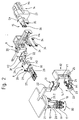
- 1 to 9 with 1 is a twisting device referred to a pair of conductors 3 by means of the conductors 2 be twisted.
- the head 2 are over a Feed station 2.1 from a cable reel, not shown Device for wire end processing 4-7 fed.
- a first swivel unit 4 serves as a feeder for the Processing of the leading leader ends in the individual Processing stations.
- the automatic grommet 6 can be arranged in front of the first crimping machine 7 or not be equipped.
- the ladder 2 is from the first swivel unit 4 and has been gripped by a second swivel unit 10. Then the conductors 2 are stripped by means of the stripping device 5 separated and stripped. The trailing leader ends are held by means of the second swivel unit 9 and stripped from the stripping device 5. The trailing leader ends are from the second Swivel unit 10 to a second automatic crimping machine 11 brought to the end of each conductor with a contact connects crimp technically. After editing and The lagging conductor ends are one Transfer module 12. Then the swings second swivel unit 10 back and can take over the next leader.
- the transfer module 12 brings the trailing conductor ends to a smaller one, from the takeover module 9 to the leading lead ends already set Conductor spacing. At the same time, the transfer module 12 swivels by 90 °, brings the trailing conductor ends to an upper one Position and passes the conductor ends to a holding module 13. Simultaneously with the transfer of the conductor from the transfer module 12 to the holding module 13, the leading conductor ends from Transfer module 9 to one at a along a third Rail 14.1 movable twisting slide 14 arranged Twisting head 15 brought. Then there is one Extension of the conductor 2 and then the twisting of the Pair of conductors while maintaining a predetermined tensile force. After twisting, the pair of conductors is placed in a storage compartment 16.
- Cable-specific parameters such as tensile strength at Twist, lay length, free connection specific Conductor lengths are specified.
- the length of the pair of conductors is shortened accordingly the twisting slide also moves in compliance with the predetermined tensile forces.
- the untwisted cable length is depending on the cable diameter and the above Parameters and is calculated by a program.
- the Pull-out slide 8, the take-over module 9 and the Twist slide 14 move to the calculated Positions.
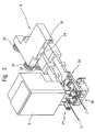
- Fig. 2 shows the directions of movement of the individual Units for handling the pairs of conductors.
- the first with the second swivel unit 10 is shown comparable swivel unit 4.
- the swivel units 4, 10 can a first or a second rotary movement D2 To run.
- the swivel units 4, 10 serve as feeders the cable ends to the processing and transfer units and are each with a first or second pair of grippers 17, 18 equipped.
- the grippers 17, 18 are pivotable on one Boom 19 stored and are each by means of a Swivel drive 20.1,20.2 swiveled.
- the holding module 13 is with a first double gripper 13.1 firmly arranged on a support 22 and is from Transfer module 12 operated with wire ends.
- the transfer module 12 is the second swivel unit 10 with conductor ends operated by a third pair of grippers 23,24 be recorded, which after the takeover the Conductor ends by means of a first horizontal movement H1 bring a smaller conductor spacing.
- the leader ends are by means of a third rotary movement D3 by 90 ° and a first vertical movement V1 to the holding module 13 fed, the third pair of grippers 23,24 by means of a rotatable and vertically displaceable console 25 movable is.
- Pull-out slide 8 On the guided and movable by means of first rollers 26 Pull-out slide 8 is a fourth pair of grippers 27, 28 arranged by means of a second horizontal movement H2 take over the conductor ends on the stripping device 5 and extend the conductor 2 to the desired length, whereby per gripper 27, 28 a force sensor 29, 30 the tensile force in the Head 2 captured.
- the extended ladder 2 are from a fifth pair of grippers 31, 32 of the takeover module 8 accepted.
- the fifth pair of grippers 31, 32 is on one second console 33 arranged a second Vertical movement V2 and a third horizontal movement H3 and can perform a fourth horizontal movement H4.
- To A third party will take over the takeover Horizontal movement H3 brought to a smaller distance, moved vertically down and horizontally the twisting head 15 fed.
- the takeover module is by means of second roles 34 guided and movable.
- Twisting slide 14 arranged twisting head 15 holds the Conductor ends fixed by means of a second double gripper 36. While the conductor twisting is carried out on a third console 37 of the twisting slide 14 arranged twisting head 14 a fourth rotary movement D4 and the twisting slide 14 shifts in the direction of the ladder by means of a fifth Horizontal movement H5.
- Fig. 3 shows details of the slide 8 in the Not taking over the leading leader ends shown contacts or with contacts and grommets.
- the flat fourth gripper pair 27.28 reaches through the Stripping device 5 and takes over from the first pivot unit 4 the conductor ends.
- the Stripping device 4 is provided with a plurality of double knives 38 equipped, the knife on the slide-out side Wire separation and the swivel unit side knives of the Serve as stripping.
- Fig. 4 shows details of the takeover module 9 in the Picking up leader ends from pull-out slide 8.
- the fifth Gripper pair 31.32 grips from above on the fourth Gripper pair 27, 28 of the slide 8 held Ends and then leads the second Vertical movement V2 down to the level of Middle of the twisting head 15.
- the second console 33 moved along a linear guide 39 until the Conductor ends as shown in Fig. 5 from the second double gripper 36 of the twisting head 15 can be detected.
- Fig. 6 shows the second pivot unit 10 and that Transfer module 12 in the handling of conductor ends.
- the second swivel unit 10 drives the second, for example Automatic crimping machines 11 with a pair of conductors for assembly with contacts, being in the working area of the crimping machine 11 the one gripper 17, 18 from the working area of the Crimping machine 11 is pivoted and the other gripper 17, 18 operated the crimping machine with one end of the conductor.
- the Transfer module 12 is with a pair of conductors according to the Takeover shown. The conductor spacing is now determined using the first horizontal movement H1 on the gripper grid of the Holding module 12 reduced. Then it will A pair of conductors as described above for the holding module 12 to hand over.
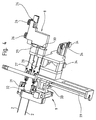
- Fig. 7 shows the holding module 12 with a pair of conductors in front of the Twist.
- the conductor 2 are by means of the first Double gripper 13.1.
- a force sensor 40 detects the tensile force in the pair of conductors.
- a not shown Regulation can be due to the tensile force during twisting regulate the force specification and the measured force.
- the first swivel unit 4 shown in FIG. 8 is used for the Feeding the leading conductor ends 2.1, 2.2, in Technical jargon called page 1, to the processing stations 5,6,7.
- the conductor ends 2.1.2.2 are by means of Pull-out slide 8 pulled by the grippers 4.1,4.2.
- the Grippers 4.1,4.2 have guide tubes on the machining side 4.1.1.4.2.1 on which of the leadership of the conductor ends 2.1.2.2 serve.
- the structure of the grippers 4.1.4.2 of page 1 is in such a way that they only cover the conductor ends 2.1.2.2 can hold on.
- Grippers 4.1.4.2 are made by means of quarter turn actuators 4.4.4.5 individually pivotable, depending on the position is from processing station 5,6,7.
- the gripper 4.1.4.2 For free rotation the gripper 4.1.4.2 from a processing station to other processing station, the grippers 4.1.4.2 moved linearly against the platform 4.6.
- this Boom 4.3 and part-turn actuators 4.4,4.5 linear slidably arranged on a rotatable platform 4.6.
- the drives for the linear movement are not shown or for the rotary movement.
- the grippers sweep 4.1.4.2 back to the stripping device 5. Then they will Head 2 by means of the slide 8 to the desired Extended length and the trailing conductor ends, in Technical jargon called page 2, from the second swivel unit 10 taken over according to FIG. 9.
- the second swivel unit 10 9 is equipped with grippers 17, 18, which the Grasp, hold on to or let go of conductor ends. to Execution of these functions are gripper jaws 17.1, 18.1 necessary that can open and close.
- Fig. 9 shows the one gripper 17 with closed, interlocking gripper jaws 17.1 and the other Gripper 18 with open gripper jaws 18.1.
Landscapes
- Engineering & Computer Science (AREA)
- Manufacturing & Machinery (AREA)
- Manufacturing Of Electrical Connectors (AREA)
- Processes Specially Adapted For Manufacturing Cables (AREA)
Priority Applications (1)
| Application Number | Priority Date | Filing Date | Title |
|---|---|---|---|
| EP20000102946 EP1032095B1 (fr) | 1999-02-23 | 2000-02-14 | Méthode et appareil pour usiner et tordre un paire de conducteurs |
Applications Claiming Priority (3)
| Application Number | Priority Date | Filing Date | Title |
|---|---|---|---|
| EP99810159 | 1999-02-23 | ||
| EP99810159 | 1999-02-23 | ||
| EP20000102946 EP1032095B1 (fr) | 1999-02-23 | 2000-02-14 | Méthode et appareil pour usiner et tordre un paire de conducteurs |
Publications (3)
| Publication Number | Publication Date |
|---|---|
| EP1032095A2 true EP1032095A2 (fr) | 2000-08-30 |
| EP1032095A3 EP1032095A3 (fr) | 2008-05-14 |
| EP1032095B1 EP1032095B1 (fr) | 2013-05-22 |
Family
ID=26070537
Family Applications (1)
| Application Number | Title | Priority Date | Filing Date |
|---|---|---|---|
| EP20000102946 Expired - Lifetime EP1032095B1 (fr) | 1999-02-23 | 2000-02-14 | Méthode et appareil pour usiner et tordre un paire de conducteurs |
Country Status (1)
| Country | Link |
|---|---|
| EP (1) | EP1032095B1 (fr) |
Cited By (29)
| Publication number | Priority date | Publication date | Assignee | Title |
|---|---|---|---|---|
| EP1447888A1 (fr) * | 2003-02-17 | 2004-08-18 | Komax Holding Ag | Pince pour un dispositif pour traiter des câbles |
| EP1548903A1 (fr) * | 2003-12-22 | 2005-06-29 | komax Holding AG | Dispositif pour le traitement de câbles |
| US7043825B2 (en) | 2003-02-17 | 2006-05-16 | Komax Holding Ag | Cable-processing device |
| US7363693B2 (en) | 2003-12-22 | 2008-04-29 | Komax Holding Ag | Wire-processing device |
| DE102007018555A1 (de) * | 2007-04-18 | 2008-10-23 | Schäfer Werkzeug- und Sondermaschinenbau GmbH | Kabelbearbeitungseinrichtung |
| WO2009017653A1 (fr) * | 2007-07-27 | 2009-02-05 | Tyco Electronics Corporation | Dispositif de positionnement de fil pour une machine de terminaison de fil |
| EP2421102A1 (fr) * | 2010-08-19 | 2012-02-22 | Komax Holding AG | Dispositif et procédé destinés à la formation d'une boucle de câble |
| WO2013068981A1 (fr) | 2011-11-11 | 2013-05-16 | Schleuniger Holding Ag | Tête de torsadage et dispositif de torsadage |
| WO2013068990A1 (fr) | 2011-11-11 | 2013-05-16 | Schleuniger Holding Ag | Dispositif de torsadage |
| DE102012213391A1 (de) * | 2012-07-31 | 2014-05-22 | Bayerische Motoren Werke Aktiengesellschaft | Vorrichtung und Verfahren zum Verdrillen und Ausrichten eines nicht verdrillten Endes eines teilweise verdrillten Kabels |
| EP2801984A1 (fr) | 2013-05-08 | 2014-11-12 | Schleuniger Holding AG | Poignée, tête de torsadage et dispositif de torsadage |
| US9132985B2 (en) | 2011-11-11 | 2015-09-15 | Schleuniger Holding Ag | Conveying device for leads |
| EP3012842A1 (fr) | 2014-10-24 | 2016-04-27 | Schleuniger Holding AG | Dispositif de toronnage avec écart réglable des extrémités de ligne |
| EP3012841A1 (fr) | 2014-10-24 | 2016-04-27 | Schleuniger Holding AG | Dispositif de guidages d'extrémités de conduite sur un dispositif de transformation |
| US9475669B2 (en) | 2008-05-20 | 2016-10-25 | Schleuniger Holding Ag | Cable transport device |
| US9624045B2 (en) | 2011-11-11 | 2017-04-18 | Schleuniger Holding Ag | Cable gathering device (wire stacker) |
| EP3272469A1 (fr) * | 2016-07-18 | 2018-01-24 | Komax Holding AG | Dispositif de positionnement d'un module outil d'une machine de traitement de cable |
| DE102016015717B4 (de) | 2016-05-18 | 2019-07-04 | Lisa Dräxlmaier GmbH | Verdrilleinrichtung |
| CN110034480A (zh) * | 2018-01-12 | 2019-07-19 | 库迈思控股股份公司 | 处理多根导线的装置及方法 |
| US10723584B2 (en) | 2016-10-03 | 2020-07-28 | Komax Holding Ag | Method and device for aligning prefabricated cable ends of a cable harness in correct rotational position |
| US10804668B2 (en) | 2016-10-03 | 2020-10-13 | Komax Holding Ag | Device for assembling a plug housing |
| CN113223781A (zh) * | 2021-05-07 | 2021-08-06 | 博众精工科技股份有限公司 | 一种扭线机构 |
| CN113708193A (zh) * | 2021-09-14 | 2021-11-26 | 中国铁建电气化局集团有限公司 | 一种用于信号机房焊接线的剪线扭线装置及方法 |
| WO2021259504A1 (fr) | 2020-06-26 | 2021-12-30 | Komax Holding Ag | Procédé et dispositif de torsion de câbles individuels |
| CN114005613A (zh) * | 2021-11-02 | 2022-02-01 | 安徽蓝锐电子科技有限公司 | 一种绞线机构 |
| EP4177909A1 (fr) | 2021-11-04 | 2023-05-10 | komax Holding AG | Dispositif et procédé de torsion des lignes individuelles |
| EP4177908A1 (fr) | 2021-11-04 | 2023-05-10 | komax Holding AG | Dispositif et procédé de torsion de lignes individuelles |
| EP4177910A1 (fr) | 2021-11-04 | 2023-05-10 | komax Holding AG | Dispositif et procédé de torsadage de conduites individuelles |
| EP4701005A1 (fr) | 2024-08-21 | 2026-02-25 | komax Holding AG | Dispositif et procédé de traitement d'une pluralité de lignes électriques |
Families Citing this family (7)
| Publication number | Priority date | Publication date | Assignee | Title |
|---|---|---|---|---|
| DE102012216895B3 (de) * | 2012-09-20 | 2013-12-05 | S-Y Systems Technologies Europe Gmbh | Verdrillen von Leitungen mit Vorsteckelement |
| EP3163586B1 (fr) | 2015-10-28 | 2018-07-04 | Schleuniger Holding AG | Dispositif de câblage de lignes électriques |
| DE102015121759A1 (de) | 2015-12-14 | 2017-06-14 | Lisa Dräxlmaier GmbH | Verdrillen von Einzelleitungen |
| DE102016109151B3 (de) * | 2016-05-18 | 2017-09-14 | Lisa Dräxlmaier GmbH | Verdrilleinrichtung |
| DE102016109155B3 (de) * | 2016-05-18 | 2017-08-03 | Lisa Dräxlmaier GmbH | Verdrillanlage, Tandem-Verdrillanlage und Verfahren zum Bestücken eines Verdrillkopfs |
| DE202017103152U1 (de) * | 2017-05-24 | 2018-08-27 | Pro.Eff Gmbh | Vorrichtung zum Verdrillen von Leitungen |
| RS61716B1 (sr) | 2018-04-17 | 2021-05-31 | Komax Holding Ag | Uređaj i postupak za upredanje prvog i drugog jednožilnog električnog voda radi obrazovanja dvožilnog voda |
Family Cites Families (2)
| Publication number | Priority date | Publication date | Assignee | Title |
|---|---|---|---|---|
| DE19649759C2 (de) * | 1996-11-20 | 2001-02-22 | Baumann Gmbh | Verfahren zum Herstellen von verdrillten Leitungen sowie Vorrichtung zum Durchführen des Verfahrens |
| JP3409643B2 (ja) * | 1997-06-05 | 2003-05-26 | 住友電装株式会社 | ツイスト電線製造装置 |
-
2000
- 2000-02-14 EP EP20000102946 patent/EP1032095B1/fr not_active Expired - Lifetime
Cited By (45)
| Publication number | Priority date | Publication date | Assignee | Title |
|---|---|---|---|---|
| US7043825B2 (en) | 2003-02-17 | 2006-05-16 | Komax Holding Ag | Cable-processing device |
| EP1447888A1 (fr) * | 2003-02-17 | 2004-08-18 | Komax Holding Ag | Pince pour un dispositif pour traiter des câbles |
| EP1548903A1 (fr) * | 2003-12-22 | 2005-06-29 | komax Holding AG | Dispositif pour le traitement de câbles |
| US7363693B2 (en) | 2003-12-22 | 2008-04-29 | Komax Holding Ag | Wire-processing device |
| DE102007018555A1 (de) * | 2007-04-18 | 2008-10-23 | Schäfer Werkzeug- und Sondermaschinenbau GmbH | Kabelbearbeitungseinrichtung |
| DE102007018555B4 (de) * | 2007-04-18 | 2009-02-19 | Schäfer Werkzeug- und Sondermaschinenbau GmbH | Kabelbearbeitungseinrichtung |
| WO2009017653A1 (fr) * | 2007-07-27 | 2009-02-05 | Tyco Electronics Corporation | Dispositif de positionnement de fil pour une machine de terminaison de fil |
| US7774927B2 (en) | 2007-07-27 | 2010-08-17 | Tyco Electronics Corporation | Wire positioning device for a wire termination machine |
| US9475669B2 (en) | 2008-05-20 | 2016-10-25 | Schleuniger Holding Ag | Cable transport device |
| EP2421102A1 (fr) * | 2010-08-19 | 2012-02-22 | Komax Holding AG | Dispositif et procédé destinés à la formation d'une boucle de câble |
| US10014644B2 (en) | 2010-08-19 | 2018-07-03 | Komax Holding Ag | Apparatus and method for forming a wire loop |
| WO2013068990A1 (fr) | 2011-11-11 | 2013-05-16 | Schleuniger Holding Ag | Dispositif de torsadage |
| US9132985B2 (en) | 2011-11-11 | 2015-09-15 | Schleuniger Holding Ag | Conveying device for leads |
| US9416488B2 (en) | 2011-11-11 | 2016-08-16 | Schleuniger Holding Ag | Twisting apparatus |
| US9624045B2 (en) | 2011-11-11 | 2017-04-18 | Schleuniger Holding Ag | Cable gathering device (wire stacker) |
| WO2013068981A1 (fr) | 2011-11-11 | 2013-05-16 | Schleuniger Holding Ag | Tête de torsadage et dispositif de torsadage |
| DE102012213391A1 (de) * | 2012-07-31 | 2014-05-22 | Bayerische Motoren Werke Aktiengesellschaft | Vorrichtung und Verfahren zum Verdrillen und Ausrichten eines nicht verdrillten Endes eines teilweise verdrillten Kabels |
| EP2801984A1 (fr) | 2013-05-08 | 2014-11-12 | Schleuniger Holding AG | Poignée, tête de torsadage et dispositif de torsadage |
| US9624607B2 (en) | 2013-05-08 | 2017-04-18 | Schleuniger Holding Ag | Gripper, twisting head and twisting device |
| EP3012842A1 (fr) | 2014-10-24 | 2016-04-27 | Schleuniger Holding AG | Dispositif de toronnage avec écart réglable des extrémités de ligne |
| EP3012841A1 (fr) | 2014-10-24 | 2016-04-27 | Schleuniger Holding AG | Dispositif de guidages d'extrémités de conduite sur un dispositif de transformation |
| DE102016015717B4 (de) | 2016-05-18 | 2019-07-04 | Lisa Dräxlmaier GmbH | Verdrilleinrichtung |
| US10671045B2 (en) | 2016-07-18 | 2020-06-02 | Komax Holding Ag | Positioning device of a processing module of a cable processing machine |
| EP3272469A1 (fr) * | 2016-07-18 | 2018-01-24 | Komax Holding AG | Dispositif de positionnement d'un module outil d'une machine de traitement de cable |
| US10723584B2 (en) | 2016-10-03 | 2020-07-28 | Komax Holding Ag | Method and device for aligning prefabricated cable ends of a cable harness in correct rotational position |
| US10804668B2 (en) | 2016-10-03 | 2020-10-13 | Komax Holding Ag | Device for assembling a plug housing |
| CN110034480B (zh) * | 2018-01-12 | 2022-02-18 | 库迈思控股股份公司 | 处理多根导线的装置及方法 |
| CN110034480A (zh) * | 2018-01-12 | 2019-07-19 | 库迈思控股股份公司 | 处理多根导线的装置及方法 |
| US12354765B2 (en) | 2020-06-26 | 2025-07-08 | Komax Holding Ag | Method and device for twisting single cables |
| WO2021259504A1 (fr) | 2020-06-26 | 2021-12-30 | Komax Holding Ag | Procédé et dispositif de torsion de câbles individuels |
| CN113223781B (zh) * | 2021-05-07 | 2023-03-14 | 博众精工科技股份有限公司 | 一种扭线机构 |
| CN113223781A (zh) * | 2021-05-07 | 2021-08-06 | 博众精工科技股份有限公司 | 一种扭线机构 |
| CN113708193B (zh) * | 2021-09-14 | 2024-04-19 | 中国铁建电气化局集团有限公司 | 一种用于信号机房焊接线的剪线扭线装置及方法 |
| CN113708193A (zh) * | 2021-09-14 | 2021-11-26 | 中国铁建电气化局集团有限公司 | 一种用于信号机房焊接线的剪线扭线装置及方法 |
| CN114005613B (zh) * | 2021-11-02 | 2023-11-14 | 安徽蓝锐电子科技有限公司 | 一种绞线机构 |
| CN114005613A (zh) * | 2021-11-02 | 2022-02-01 | 安徽蓝锐电子科技有限公司 | 一种绞线机构 |
| EP4177910A1 (fr) | 2021-11-04 | 2023-05-10 | komax Holding AG | Dispositif et procédé de torsadage de conduites individuelles |
| JP2023070152A (ja) * | 2021-11-04 | 2023-05-18 | コマックス ホルディング アクチエンゲゼルシャフト | 単一ケーブルを撚り合わせるための装置及び方法 |
| US11833574B2 (en) | 2021-11-04 | 2023-12-05 | Komax Holding Ag | Device and method for twisting single cables |
| US11833575B2 (en) | 2021-11-04 | 2023-12-05 | Komax Holding Ag | Device and method for twisting single cables |
| EP4177908A1 (fr) | 2021-11-04 | 2023-05-10 | komax Holding AG | Dispositif et procédé de torsion de lignes individuelles |
| JP7561807B2 (ja) | 2021-11-04 | 2024-10-04 | コマックス ホルディング アクチエンゲゼルシャフト | 単一ケーブルを撚り合わせるための装置及び方法 |
| US12142391B2 (en) | 2021-11-04 | 2024-11-12 | Komax Holding Ag | Device and method for twisting single cables |
| EP4177909A1 (fr) | 2021-11-04 | 2023-05-10 | komax Holding AG | Dispositif et procédé de torsion des lignes individuelles |
| EP4701005A1 (fr) | 2024-08-21 | 2026-02-25 | komax Holding AG | Dispositif et procédé de traitement d'une pluralité de lignes électriques |
Also Published As
| Publication number | Publication date |
|---|---|
| EP1032095A3 (fr) | 2008-05-14 |
| EP1032095B1 (fr) | 2013-05-22 |
Similar Documents
| Publication | Publication Date | Title |
|---|---|---|
| EP1032095B1 (fr) | Méthode et appareil pour usiner et tordre un paire de conducteurs | |
| DE2649920C2 (de) | Kontaktieranlage für isolierte elektrische Leitungsdrähte | |
| EP1988045B1 (fr) | Machine de préparation de câbles et procédé destiné à la fabrication et au traitement d'une section de câble | |
| DE3838706C2 (de) | Verfahren zum Herstellen eines Kabelbaumes und Vorrichtung zur Durchführung dieses Verfahrens | |
| DE69133081T2 (de) | Mehrklingenentmantelungsapparat für Kabel und Draht | |
| DE3340744C2 (fr) | ||
| DE2549833C2 (de) | Verfahren und Vorrichtung zur Zuführung einer Mehrzahl von Drähten | |
| DE2649534C2 (de) | Verfahren und Vorrichtung zum Herstellen eines Kabelbaums | |
| DE69409218T2 (de) | Verfahren und Vorrichtung zum Wickeln eines Bandes | |
| EP2565992B1 (fr) | Dispositif et procédé d'amenée d'extrémités de câble vers des unités de confection | |
| DE3015846A1 (de) | Verfahren und vorrichtung zum automatischen positionieren der enden von drahtabschnitten | |
| EP1387449B1 (fr) | Appareil et méthode pour enrouler des câbles | |
| EP1231692A1 (fr) | Dispositif pour dénuder un câble multibrin | |
| EP3557592A1 (fr) | Dispositif et procédé de torsadage d'une première et d'une seconde ligne électrique individuelle pour obtenir une paire de lignes | |
| WO2019134849A1 (fr) | Procédé et dispositif de fabrication de rotors et de stators, incluant la confection de fils de connexion | |
| DE102010017981A1 (de) | Einrichtung und Verfahren zum Zusammenführen von Leitern | |
| DE202010001324U1 (de) | Vorrichtung zum Verdrillen von Leitungen | |
| EP1251605B1 (fr) | Appareil et méthode pour l'insertion de bout de câble dans des boítiers de connecteurs | |
| DE202007013417U1 (de) | Vorrichtung zur Herstellung langer, konfektionierter, elektrischer Leitungen in einem CrimpCenter | |
| EP0584493B1 (fr) | Dispositif à faire un paquet pour machines de traitement de câbles | |
| DE2507384B2 (de) | Vorrichtung zum Herstellen von an beiden Enden abisolierten und bearbeiteten elektrischen Leiterabschnitten | |
| EP1988044B1 (fr) | Enrouleur et procédé destiné à la fabrication d'un rouleau | |
| DE3878003T2 (de) | Einrichtung fuer die herstellung von elektrischen kabelanordnungen. | |
| DE2318253B2 (de) | Vorrichtung zum Umbinden von Drahtspulen mit Bindedraht | |
| DE112023005622T5 (de) | Kabelbaum-Herstellungsgerät und Kabelbaum-Herstellungsverfahren |
Legal Events
| Date | Code | Title | Description |
|---|---|---|---|
| PUAI | Public reference made under article 153(3) epc to a published international application that has entered the european phase |
Free format text: ORIGINAL CODE: 0009012 |
|
| AK | Designated contracting states |
Kind code of ref document: A2 Designated state(s): AT BE CH CY DE DK ES FI FR GB GR IE IT LI LU MC NL PT SE |
|
| AX | Request for extension of the european patent |
Free format text: AL;LT;LV;MK;RO;SI |
|
| PUAL | Search report despatched |
Free format text: ORIGINAL CODE: 0009013 |
|
| AK | Designated contracting states |
Kind code of ref document: A3 Designated state(s): AT BE CH CY DE DK ES FI FR GB GR IE IT LI LU MC NL PT SE |
|
| AX | Request for extension of the european patent |
Extension state: AL LT LV MK RO SI |
|
| 17P | Request for examination filed |
Effective date: 20081103 |
|
| AKX | Designation fees paid |
Designated state(s): CH DE FR GB IT LI |
|
| 17Q | First examination report despatched |
Effective date: 20100322 |
|
| GRAP | Despatch of communication of intention to grant a patent |
Free format text: ORIGINAL CODE: EPIDOSNIGR1 |
|
| GRAS | Grant fee paid |
Free format text: ORIGINAL CODE: EPIDOSNIGR3 |
|
| GRAA | (expected) grant |
Free format text: ORIGINAL CODE: 0009210 |
|
| AK | Designated contracting states |
Kind code of ref document: B1 Designated state(s): CH DE FR GB IT LI |
|
| REG | Reference to a national code |
Ref country code: GB Ref legal event code: FG4D Free format text: NOT ENGLISH |
|
| REG | Reference to a national code |
Ref country code: CH Ref legal event code: EP |
|
| REG | Reference to a national code |
Ref country code: DE Ref legal event code: R096 Ref document number: 50016313 Country of ref document: DE Effective date: 20130718 |
|
| PLBE | No opposition filed within time limit |
Free format text: ORIGINAL CODE: 0009261 |
|
| STAA | Information on the status of an ep patent application or granted ep patent |
Free format text: STATUS: NO OPPOSITION FILED WITHIN TIME LIMIT |
|
| 26N | No opposition filed |
Effective date: 20140225 |
|
| PGFP | Annual fee paid to national office [announced via postgrant information from national office to epo] |
Ref country code: FR Payment date: 20140219 Year of fee payment: 15 |
|
| REG | Reference to a national code |
Ref country code: DE Ref legal event code: R097 Ref document number: 50016313 Country of ref document: DE Effective date: 20140225 |
|
| GBPC | Gb: european patent ceased through non-payment of renewal fee |
Effective date: 20140214 |
|
| PG25 | Lapsed in a contracting state [announced via postgrant information from national office to epo] |
Ref country code: GB Free format text: LAPSE BECAUSE OF NON-PAYMENT OF DUE FEES Effective date: 20140214 |
|
| REG | Reference to a national code |
Ref country code: CH Ref legal event code: NV Representative=s name: INVENTIO AG, CH |
|
| REG | Reference to a national code |
Ref country code: FR Ref legal event code: ST Effective date: 20151030 |
|
| PG25 | Lapsed in a contracting state [announced via postgrant information from national office to epo] |
Ref country code: FR Free format text: LAPSE BECAUSE OF NON-PAYMENT OF DUE FEES Effective date: 20150302 |
|
| PGFP | Annual fee paid to national office [announced via postgrant information from national office to epo] |
Ref country code: CH Payment date: 20190218 Year of fee payment: 20 Ref country code: IT Payment date: 20190225 Year of fee payment: 20 Ref country code: DE Payment date: 20190219 Year of fee payment: 20 |
|
| REG | Reference to a national code |
Ref country code: DE Ref legal event code: R071 Ref document number: 50016313 Country of ref document: DE |
|
| REG | Reference to a national code |
Ref country code: CH Ref legal event code: PL |