EP1032105A2 - Electrical connection box including a wire guide - Google Patents
Electrical connection box including a wire guide Download PDFInfo
- Publication number
- EP1032105A2 EP1032105A2 EP00103978A EP00103978A EP1032105A2 EP 1032105 A2 EP1032105 A2 EP 1032105A2 EP 00103978 A EP00103978 A EP 00103978A EP 00103978 A EP00103978 A EP 00103978A EP 1032105 A2 EP1032105 A2 EP 1032105A2
- Authority
- EP
- European Patent Office
- Prior art keywords
- wire guide
- connection box
- electrical connection
- wire
- wire harness
- Prior art date
- Legal status (The legal status is an assumption and is not a legal conclusion. Google has not performed a legal analysis and makes no representation as to the accuracy of the status listed.)
- Withdrawn
Links
Images


Classifications
-
- H—ELECTRICITY
- H02—GENERATION; CONVERSION OR DISTRIBUTION OF ELECTRIC POWER
- H02G—INSTALLATION OF ELECTRIC CABLES OR LINES, OR OF COMBINED OPTICAL AND ELECTRIC CABLES OR LINES
- H02G3/00—Installations of electric cables or lines or protective tubing therefor in or on buildings, equivalent structures or vehicles
- H02G3/26—Installations of cables, lines, or separate protective tubing therefor directly on or in walls, ceilings, or floors
Definitions
- the present Invention is directed to an electrical connection box having a guide for a wire harness. More specifically, the guide directs the wire harness out of the box for further connection to various electrical elements used particularly in automotive electrical circuits.
- the device fixes the harness by the use of a tying band to prevent undesired movement.
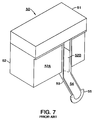
- FIGS 7 and 8 show a typical prior art connection box having a wire guide projecting therefrom.
- Connection box 50 is comprised of cover 51 and housing 52.
- the desired electrical elements (not shown) are within the housing.
- Cut out 52B is provided in front 52A, which is one of the outer perimeter surfaces of housing 52. The cut out extends from the upper end to the lower end of front 52A.
- Wire guard 53 is in the shape of a half-cylinder extending diagonally downward from front 52A, with groove 54 facing up. This groove is continuous with cut out 52B.
- Flange 55 with its plane parallel to front 52A, is located at the end of wire guide 53 remote from front 52A. The angle of wire guide 53 to front 52A is determined by the nature and location of the electrical elements within housing 52, as well as the electrical elements outside the housing to which the wire harness is to be connected.
- wire harness 57 extends from the unillustrated electrical elements in housing 52 through cut out 52B and is restricted by the semi-circular groove of guide 53.
- the wire harness is retained in guide 53 by tying band 56.
- the band is wrapped around guide 53 and its position is determined by flange 55.
- flange 55 defines the position at which wire harness 57 is located relative to wire guide 53, while also preventing tying band 56 from slipping off the end of the wire guide.
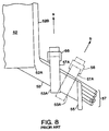
- tying band 56 be tightened in the direction indicated by arrow b, i.e. perpendicular to wire guide 53. This is most reliable and prevents loosening.
- the force is actually applied in the direction of arrow a. This is required because of the presence of other elements crowded in the engine compartment.
- gap 57A is formed between the wire harness and the tying band
- gap 53A is formed between the wire guide and the tying band.
- wire harness 57 Since the various electrical elements to which wire harness 57 is connected are fixed, any movement by the harness causes problems of undue tension or too much slack, thus leaving the assembly open to electrical problems. Alternatively, the length of wire harness 57 will have to be adjusted or the harness moved back to its original position in order to provide reliable connections. It may even be necessary to reattach the tying band.
- an electrical connection box wherein the wire harness is reliably and firmly affixed to the wire guide.
- an electrical connection box is provided wherein the wire guide projects outwardly from the front of the box and is adapted to receive the wire harness.
- An opening is located in the wire guide and the tying band passes through the opening and around the wire harness and wire guide.
- there are two openings one adjacent each of the edges of the wire guide and the tying band passes through both. This provides added security.
- the tying band desirably comprises a strap having a head adjacent one end with a hole therethrough.
- the strap after passing around the wire harness and wire guide and through the opening(s), is inserted into the hole and retained either by friction or a ratchet and pawl mechanism. It has been found useful, in this embodiment of the Invention, that the wire guide project from the lower end of the cut out.
- the wire harness passes through the cut out and rests on the upper side of the wire guide.
- an insertion ring mounted on the guide, having an opening parallel to the surface of the guide and perpendicular to the axis of the wire harness.
- the ring is either fixed to the wire guide or the wire guide constitutes one side of the ring.
- the tying band passes through the opening in the ring and secures the wire harness thereto. Since the ring is fixed to the guide, the band is secure in its position and cannot move.
- the wire harness When the wire guide is located at the upper end of the cut out, the wire harness is affixed to the underside thereof. Thus, by locating the wire guide at either the top or the bottom of the cut out, the wire harness can be located either against the bottom or top surface thereof. This provides desirable flexibility in the design and assembly of the connection box.
- the wire guide has an insertion opening adjacent one edge and a notch in the other edge opposite the insertion opening.
- the tying band passes around the wire harness, through the opening and is in the notch.
- the wire guide is provided, at its remote end, with a flange substantially parallel to the front of the connection box.
- An insertion ring is provided alongside the flange and the band is passed therethrough.
- the band passes through bath.
- a pair of side walls can be located adjacent the edges of the guide at the end near the connection box in any of the foregoing embodiments.
- the walls are affixed to both the front of the connection box and the wire guide.
- the wire guide can be arcuate in cross section so that it at least partially surrounds the wire harness. This will provide still further security.
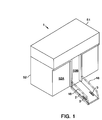
- connection box 1 comprises housing 52 and cover 51. Front 52A has cut out 52B from which wire guide 2 projects. Adjacent the edges of wire guide 2 are insertion openings 3. Wire harness 57 rests on wire guide 2 and is secured thereto by tying band 56.
- the tying band comprises strap 56A and head 56B. The band passes through insertion openings 3 and one end is within head 56B. It is retained therein, preferably either by friction or a ratchet and pawl combination.
- side walls 18 are provided on the edges of wire guide 2 in order to both provide additional strength and to assist in retaining the wire harness. These walls are shown in broken lines in Figure 1.
- FIG. 4 illustrates the second embodiment of this Invention.
- Connection box 10 has cut out 52C and wire guide 11.
- the latter has mounted thereon, preferably as part thereof, insertion ring 13.
- This ring has an opening which passes through it in a direction parallel to front 52A of the connection box.
- Strap 56A of tying band 56 passes through insertion ring 13, around wire harness 57, and into the hole in head 56B. It is retained therein in the same manner as in the first embodiment., i.e. by friction or a ratchet and pawl or the like.
- insertion opening 3 is adjacent one edge of the wire guide. Opposite opening 3 is notch 16.
- the tying band passes through insertion opening 3 and fits within notch 16. The strap is inserted into the hole in head 56B and retained therein as in the first and second embodiments.
- Figure 6 is a fourth embodiment of the Invention. Insertion rings 13 are on both edges of wire guide 11 adjacent flange 15. The band passes through both and bears against the flange. This provides still further security and reliability. Additional insertion rings can be provided if deemed desirable and, in such a case, the tying band would pass through all such rings.
- the various embodiments of the present Invention have substantial and important advantages over conventional connection boxes of this type. Because the tying band, in all cases, passes through at least one fixed opening in the wire guide, it will neither disengage from the guide nor slip off the end thereof. Furthermore, it will not shift its position as can happen with the device as shown in Figure 8.
- the insertion openings are smaller than the head of the band, this permits the head to be abutted against the insertion opening without any risk of it passing through. This further aids in limiting any possible movement of the band relative to the guide and makes installation easier. Moreover, the structure is very simple and can easily and economically be produced.
- the second embodiment of the present Invention provides an additional advantage in that the location of the insertion ring on the wire guide provides clear visibility thereof during wiring and tightening.
- the insertion ring can be a separate and complete element affixed to the wire guide, it is preferable that a section of the wire guide constitute a side of the ring. When this is done, the amount of resin material needed is reduced, thus having a favorable effect on production costs.
- the positions of the insertion openings could be modified in accordance with the dictates of specific arrangements of electrical elements.
- the wire harness could be located on either the upper or lower surface of the wire guide, and the relationship between the cut out and the wire guide modified accordingly.
- the wire guides are not limited to a flat shape, but rather could be arcuate, semi-circular, or the like.
- the insertion ring include a portion of the wire guide. This functions as one side thereof.
- the wire guide complete in itself and otherwise affixed to the wire guide. A plurality of such rings could be used, with the tying band passing through all.
Landscapes
- Engineering & Computer Science (AREA)
- Architecture (AREA)
- Civil Engineering (AREA)
- Structural Engineering (AREA)
- Insertion, Bundling And Securing Of Wires For Electric Apparatuses (AREA)
- Connection Or Junction Boxes (AREA)
- Details Of Connecting Devices For Male And Female Coupling (AREA)
Abstract
Description
- Figure 1
- is a perspective view of the first embodiment of the present Invention;
- Figure 2
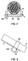
- is a partial cross section of the wire guide perpendicular to the axis of the wire harness;
- Figure 3
- is a partial cross section parallel to the axis of the wire harness;
- Figure 4
- is a view, similar to that of Figure 1, of the second embodiment;
- Figure 5
- is a fragmented plan view of the wire guide of the third embodiment;
- Figure 6
- is a view, similar to that of Figure 1, of the fourth embodiment;
- Figure 7
- is a view, similar to that of Figure 1, of a prior art connection box; and
- Figure 8
- is a view, similar to that of Figure 3, of the prior art connection box of Figure 7.
Claims (13)
- An electrical connection box (1) comprising a wire guide (2) projecting outwardly from a front (52A) of said electrical connection box (1) and adapted to receive a wire harness (57), an opening (3) through said wire guide (2), a tying band (56), around said wire harness (57) and said wire guide (2), extending through said opening (3) whereby, when said tying band (56) is tightened, said wire harness (57) is secured to said wire guide (3).
- The electrical connection box (1) of Claim 1 wherein said tying band (56) comprises a strap (56A) with a head (56B) adjacent one end, said head (56B) having a hole therethrough, another end of said tying band (56) passing through said hole and retained therein after said tying band (56) is tightened.
- The electrical connection box (1) of Claim 1 having a cut out (52B) in said front (52A), said wire guide (2) projecting from a lower end of said cut out (52B), said wire harness (57) passing through said cut out (52B) and adjacent an upper side of said wire guide (2).
- The electrical connection box (1) of Claim 1 comprising said opening (3) adjacent one edge of said wire guide (2), and a notch (16) on an opposite edge of said wire guide (2), said tying band (56) passing through said opening (3) and in said notch (16).
- The electrical connection box (1) of Claim 1 wherein a cross section of said wire guide (2) parallel to said front (52A) is arcuate whereby said wire guide (2) at least partially surrounds said wire harness (57).
- The electrical connection box (1) of Claim 2 wherein there are two openings (3), spaced apart in a first direction perpendicular to an axis of said wire guide (2), one of said openings (3) being adjacent each edge of said wire guide (2), said tying band (56) passing through both said openings (3).
- The electrical connection box (1) of claim 2 wherein said strap (56A) is retained in said head (56B) by friction or a ratchet and pawl.
- An electrical connection box (10) comprising a wire guide (11) projecting outwardly from a front (52A) of said electrical connection box (10) and adapted to receive a wire harness (57), an insertion ring (13) mounted on said wire guide (11), having an opening parallel to a surface of said wire guide (11) and perpendicular to an axis of said wire harness (57), said insertion ring (13) being fixed with respect to said wire guide (11), a tying band (56) around said wire harness (57) and passing through said opening whereby, when said tying band (56) is tightened, said wire harness (57) is secured to said wire guide (11).
- The electrical connection box (10) of Claim 8 wherein a portion of said wire guide (11) is one side of said insertion ring (13).
- The electrical connection box (10) of Claim 8 wherein there is a cut out (52C) in said front (52A), said wire guide (11) projecting from an upper end of said cut out (52C), said wire harness (57) passing through said cut out (52C) and adjacent an under side of said wire guide (11).
- The electrical connection box (1) of Claims 1 or 8 comprising a pair of side walls (12) adjacent edges of said wire guide (2) and fixed to said wire guide (2) and said front (52A).
- The electrical connection box (10) of Claim 8 comprising a flange (15) adjacent an end of said wire guide (11) remote from said front (52B), said insertion ring (13) being adjacent said flange.
- The electrical connection box (1) of claims 2, 3, or 8 wherein said head (56B) is larger than said opening.
Applications Claiming Priority (2)
| Application Number | Priority Date | Filing Date | Title |
|---|---|---|---|
| JP4822399 | 1999-02-25 | ||
| JP11048223A JP2000253536A (en) | 1999-02-25 | 1999-02-25 | Electric junction box |
Publications (2)
| Publication Number | Publication Date |
|---|---|
| EP1032105A2 true EP1032105A2 (en) | 2000-08-30 |
| EP1032105A3 EP1032105A3 (en) | 2000-11-29 |
Family
ID=12797432
Family Applications (1)
| Application Number | Title | Priority Date | Filing Date |
|---|---|---|---|
| EP00103978A Withdrawn EP1032105A3 (en) | 1999-02-25 | 2000-02-25 | Electrical connection box including a wire guide |
Country Status (4)
| Country | Link |
|---|---|
| US (1) | US6371800B1 (en) |
| EP (1) | EP1032105A3 (en) |
| JP (1) | JP2000253536A (en) |
| CN (1) | CN1264946A (en) |
Cited By (2)
| Publication number | Priority date | Publication date | Assignee | Title |
|---|---|---|---|---|
| FR2855334A1 (en) * | 2003-05-22 | 2004-11-26 | Debflex | Case for receiving electrical material e.g. switch, has cover to introduce sheath protecting wires and electrical cables required for connecting material equipped in case and band to fix end of sheath to case once sealed |
| US10814500B2 (en) | 2018-03-20 | 2020-10-27 | Fanuc Corporation | Cable clamp and robot |
Families Citing this family (10)
| Publication number | Priority date | Publication date | Assignee | Title |
|---|---|---|---|---|
| CN1825724B (en) * | 2005-09-06 | 2010-07-14 | 万家盛 | Electrical box |
| JP2007312532A (en) * | 2006-05-19 | 2007-11-29 | Kinki Sharyo Co Ltd | Wiring duct |
| JP5110688B2 (en) * | 2007-09-19 | 2012-12-26 | 矢崎総業株式会社 | Electrical junction box |
| JP5061920B2 (en) | 2008-01-23 | 2012-10-31 | 住友電装株式会社 | In-vehicle electrical junction box |
| JP5798360B2 (en) * | 2011-04-20 | 2015-10-21 | 矢崎総業株式会社 | Binding band assembly structure of the wire insertion part |
| CN102545113A (en) * | 2012-02-14 | 2012-07-04 | 奇瑞汽车股份有限公司 | Plug-wire type distribution box |
| DE102013016760A1 (en) * | 2013-10-10 | 2015-04-16 | Wabco Europe Bvba-Sprl | electronics housing |
| CN107492406A (en) * | 2017-09-22 | 2017-12-19 | 贵州固达电缆有限公司 | A kind of special cable in automobile |
| JP6626070B2 (en) * | 2017-11-10 | 2019-12-25 | 矢崎総業株式会社 | Wire harness |
| CN109281825B (en) * | 2018-09-30 | 2025-03-14 | 珠海格力电器股份有限公司 | Compressors and air conditioning units |
Family Cites Families (15)
| Publication number | Priority date | Publication date | Assignee | Title |
|---|---|---|---|---|
| US3622942A (en) * | 1970-04-27 | 1971-11-23 | Thomas & Betts Corp | Strain relief |
| US3874765A (en) * | 1973-10-17 | 1975-04-01 | Gulf & Western Industries | Connector cover |
| US3936125A (en) * | 1974-01-28 | 1976-02-03 | Bunker Ramo Corporation | Electrical connector with metal to metal seal |
| US4035051A (en) * | 1976-10-19 | 1977-07-12 | Western Electric Company, Inc. | Adjustable molded hood assembly for a cable connector plug |
| FR2485281A1 (en) * | 1980-05-12 | 1981-12-24 | Labinal | Aircraft cable grip for multipin plug - has metal plate with several pairs of slots for band gripping cable in chosen position |
| DE3318248A1 (en) * | 1983-05-19 | 1984-11-22 | Messerschmitt-Bölkow-Blohm GmbH, 8000 München | MULTIPOLE ELECTRICAL PLUG, IN PARTICULAR ROUND PLUG |
| JPH0275923U (en) * | 1988-11-30 | 1990-06-11 | ||
| JPH0736488U (en) * | 1993-12-09 | 1995-07-04 | 住友電装株式会社 | Electric connection box and electric wire holding mechanism for electric connection box |
| EP0709925B1 (en) * | 1994-10-28 | 2001-03-14 | The Whitaker Corporation | Improved receptacle housing for connector assembly |
| JPH08256423A (en) | 1995-03-17 | 1996-10-01 | Yazaki Corp | Steering column wire harness guide device and wire harness fixing method |
| JPH104619A (en) | 1996-06-13 | 1998-01-06 | Sumitomo Wiring Syst Ltd | Protector |
| JPH1080036A (en) | 1996-09-06 | 1998-03-24 | Sumitomo Wiring Syst Ltd | Structure for absorbing dimensional tolerance of wire harness |
| JPH10229283A (en) * | 1997-02-17 | 1998-08-25 | Matsushita Electric Works Ltd | Wire binding/fixing structure |
| JP3156626B2 (en) * | 1997-03-11 | 2001-04-16 | 住友電装株式会社 | Electrical junction box |
| JP3211707B2 (en) | 1997-03-11 | 2001-09-25 | 住友電装株式会社 | Electrical junction box |
-
1999
- 1999-02-25 JP JP11048223A patent/JP2000253536A/en active Pending
-
2000
- 2000-02-24 US US09/511,835 patent/US6371800B1/en not_active Expired - Lifetime
- 2000-02-25 EP EP00103978A patent/EP1032105A3/en not_active Withdrawn
- 2000-02-25 CN CN00102657.7A patent/CN1264946A/en active Pending
Cited By (3)
| Publication number | Priority date | Publication date | Assignee | Title |
|---|---|---|---|---|
| FR2855334A1 (en) * | 2003-05-22 | 2004-11-26 | Debflex | Case for receiving electrical material e.g. switch, has cover to introduce sheath protecting wires and electrical cables required for connecting material equipped in case and band to fix end of sheath to case once sealed |
| US10814500B2 (en) | 2018-03-20 | 2020-10-27 | Fanuc Corporation | Cable clamp and robot |
| DE102019106359B4 (en) | 2018-03-20 | 2024-07-11 | Fanuc Corporation | Cable clamp and robot |
Also Published As
| Publication number | Publication date |
|---|---|
| US6371800B1 (en) | 2002-04-16 |
| EP1032105A3 (en) | 2000-11-29 |
| CN1264946A (en) | 2000-08-30 |
| JP2000253536A (en) | 2000-09-14 |
Similar Documents
| Publication | Publication Date | Title |
|---|---|---|
| US6371800B1 (en) | Electrical connection box including a wire guide | |
| US6045394A (en) | Electrical connection box assembly with tapered projection | |
| US4705244A (en) | Tube protecting device | |
| US7378592B2 (en) | Protector | |
| JPH0842757A (en) | Band clip | |
| US6056587A (en) | Electrical connection box assembly | |
| US6674004B2 (en) | Wire harness | |
| US11101628B2 (en) | Wire harness retaining system | |
| KR102833037B1 (en) | Cable binding device | |
| US6149108A (en) | Cable retainer | |
| KR100707094B1 (en) | Car wire harness retaining clip | |
| JPH11150841A (en) | Corrugated tube guide clamp | |
| JP3427552B2 (en) | Wire harness mounting band | |
| KR200441886Y1 (en) | Cable fixing device of the box | |
| JP2000134763A (en) | Structure for mounting clamp on wire harness protector | |
| KR19980037661U (en) | Fastener structure for fixing wire harness cable | |
| JP3637739B2 (en) | Wire harness protector | |
| KR200388599Y1 (en) | Band cable for preventing slip | |
| JP3075140B2 (en) | Tightening band | |
| KR100205013B1 (en) | A clip for fixing wire harness of a car | |
| KR102540551B1 (en) | Wire harness protector for vehicle | |
| JPH106882A (en) | Wiring equipment for vehicles | |
| JPH109445A (en) | Wire rod tying tool | |
| KR19980044555A (en) | Versatile clip construction for securing wires and cables | |
| KR20060029029A (en) | Clips for Fixing Automotive Wire Harnesses |
Legal Events
| Date | Code | Title | Description |
|---|---|---|---|
| PUAI | Public reference made under article 153(3) epc to a published international application that has entered the european phase |
Free format text: ORIGINAL CODE: 0009012 |
|
| 17P | Request for examination filed |
Effective date: 20000225 |
|
| AK | Designated contracting states |
Kind code of ref document: A2 Designated state(s): DE FR GB IT |
|
| AX | Request for extension of the european patent |
Free format text: AL;LT;LV;MK;RO;SI |
|
| PUAL | Search report despatched |
Free format text: ORIGINAL CODE: 0009013 |
|
| AK | Designated contracting states |
Kind code of ref document: A3 Designated state(s): AT BE CH CY DE DK ES FI FR GB GR IE IT LI LU MC NL PT SE |
|
| AX | Request for extension of the european patent |
Free format text: AL;LT;LV;MK;RO;SI |
|
| AKX | Designation fees paid |
Free format text: DE FR GB IT |
|
| 17Q | First examination report despatched |
Effective date: 20071122 |
|
| STAA | Information on the status of an ep patent application or granted ep patent |
Free format text: STATUS: THE APPLICATION IS DEEMED TO BE WITHDRAWN |
|
| 18D | Application deemed to be withdrawn |
Effective date: 20080403 |