EP1032213A2 - Procédé et dispositif de transcodage vidéo - Google Patents
Procédé et dispositif de transcodage vidéo Download PDFInfo
- Publication number
- EP1032213A2 EP1032213A2 EP00103728A EP00103728A EP1032213A2 EP 1032213 A2 EP1032213 A2 EP 1032213A2 EP 00103728 A EP00103728 A EP 00103728A EP 00103728 A EP00103728 A EP 00103728A EP 1032213 A2 EP1032213 A2 EP 1032213A2
- Authority
- EP
- European Patent Office
- Prior art keywords
- input stream
- motion vector
- subpicture
- stream
- output stream
- Prior art date
- Legal status (The legal status is an assumption and is not a legal conclusion. Google has not performed a legal analysis and makes no representation as to the accuracy of the status listed.)
- Granted
Links
Images






Classifications
-
- H—ELECTRICITY
- H04—ELECTRIC COMMUNICATION TECHNIQUE
- H04N—PICTORIAL COMMUNICATION, e.g. TELEVISION
- H04N19/00—Methods or arrangements for coding, decoding, compressing or decompressing digital video signals
- H04N19/40—Methods or arrangements for coding, decoding, compressing or decompressing digital video signals using video transcoding, i.e. partial or full decoding of a coded input stream followed by re-encoding of the decoded output stream
-
- H—ELECTRICITY
- H04—ELECTRIC COMMUNICATION TECHNIQUE
- H04N—PICTORIAL COMMUNICATION, e.g. TELEVISION
- H04N19/00—Methods or arrangements for coding, decoding, compressing or decompressing digital video signals
- H04N19/60—Methods or arrangements for coding, decoding, compressing or decompressing digital video signals using transform coding
- H04N19/61—Methods or arrangements for coding, decoding, compressing or decompressing digital video signals using transform coding in combination with predictive coding
Definitions
- the present invention is related to a video coding apparatus and a method thereof for coding a digital compressed video signal having a compression format to obtain a digital coded video signal having the same, or different compression format. More specifically, the present invention is directed to such a video coding apparatus and a video coding method, capable of coding the digital compressed video signal by utilizing information about the compression of this digital compressed video signal.
- the present invention has been made to solve the above-explained problems, and therefore, has an object to achieve the following aspects:
- the present invention owns another object to shorten a process delay required in the compression format converting operation, as compared with that of the conventional compression format converting operation.
- a video coding method for performing either a partial stage of all stages of a decoding process operation with respect of an input stream and for coding the decoded digital moving picture by way of the same, or different compression format as/from the compression format of the input stream to thereby produce an output stream corresponding to a digital moving picture under different compression condition, in which the output stream is produced by utilizing added information corresponding to information other than a decoded pixel value of the input stream.
- the video coding method is featured by that when the input stream and the output stream own coding modes corresponding to information as to coding methods every subpicture, the coding mode of the output stream is determined based upon a coding mode of the corresponding subpicture of the input stream.
- the video coding method is featured by that when the output stream owns a coding mode every picture, the coding mode of the output stream is determined based upon the coding mode of the subpicture contained in the corresponding picture of the input stream.
- the video coding method includes a method for producing/referring to coding mode history information containing information for indicating how many subpictures of the output stream have been continuously inter-coded in the past for plural pictures counted from a picture under being coded; and when a subpicture which is intra-coded while the output stream is compressed is selected from a plurality of subpictures inter-coded in the input stream, the coding mode history information is utilized.
- the video coding method is featured by that when both the input stream and the output stream are compressed in the unit of a subpicture by way of a motion-compensatable format, a format of a motion vector of the input stream is changed into a format usable as a motion vector of the output stream, and the format-changed motion vector of the input stream is used as the motion vector of the output stream.
- the video coding method is featured by that a starting point for a searching operation is determined based upon a value of a motion vector of an input stream; and a motion vector searching operation is carried out so as to determine a motion vector of an output stream.
- the video coding method is featured by that when the motion vector of the input stream is such a motion vector obtained by using a filtering-processed reference image, the motion vector of the output stream is produced by converting the motion vector into a representation obtained by using a reference image to which the filtering process is not performed, and further by converting the converted motion vector into another representation which is obtained by using another filtering-processed reference image different from the reference image of the input stream.
- the video coding method is featured by that when the input stream owns both a motion vector every subpicture and subtraction information corresponding to a motion prediction error, a magnitude of the subtraction information is obtained so as to calculate an accurate degree of the motion vector, and a method for utilizing the motion vector of the input stream is changed in response to the magnitude of the accurate degree of the motion vector.
- the video coding method is featured by that a search range of a motion vector searching process operation is changed in response to the magnitude of the accurate degree of the motion vector.
- the video coding method is featured by that in response to the magnitude of the accurate degree of the motion vector, a judgement is made as to whether or not the motion vector searching process operation is carried out.
- the video coding method is featured by that in response to the magnitude of the accurate degree of the motion vector, a method for coding the corresponding subpicture of the output stream is changed.
- the video coding method is featured by that an intra picture in which an entire 1 picture is intra-coded is first detected by a video coding method for producing an output stream in the unit of a subpicture before an entire 1 picture of an input stream is entered.
- the video coding method is featured by that the intra picture is detected by executing a compression format converting process operation in the unit of the subpicture while producing intra block information corresponding to such information for recording thereon as to whether or not each of the subpictures in the picture of the input stream under process operation is intra-coded so as to detect the intra picture, and also by detecting that all of the subpictures contained in the picture under process operation are intra-coded by referring to said intra block information at a time instant when all of the subpictures contained in 1 picture are entered from the input stream.
- the video coding method is featured by comprising a method for containing a quadrature converting coefficient contained in the input stream, while not inverse-quadrature-converting the input stream into the output stream.
- the video coding method is featured by comprising a method for containing a quantized quadrature converting coefficient contained in the input stream, while not inverse-quadrature-converting and not dequantizing the input stream into the output stream.
- the video coding method is featured by that in the case that the subpicture of the input stream is intra-coded, the subpicture is intra-coded when the output stream is produced; and either the quadrature converting coefficient or the quantized quadrature converting coefficient of the subpicture of the input stream is employed as either a quadrature converting coefficient or a quantized quadrature converting coefficient of the subpicture of the output stream.
- the video coding method is featured by that when a subpicture of the input stream is inter-coded in connection with a motion compensation, the subpicture is inter-coded in connection with the motion compensation while the output stream is produced; and either a quadrature converting coefficient or a quantized quadrature converting coefficient, which corresponds to subtraction information of the subpicture of the input stream, is used as either a quadrature converting coefficient or a quantized quadrature converting coefficient, which corresponds to subtraction information of the subpicture of the output stream.
- the video coding method is featured by that with respect to a quantizing matrix indicative of a relationship between a position and a quantizing value within an area in the quadrature converting unit of each of the quadrature converting coefficient, the same quantizing matrix as that of each of the subpictures of the input stream is set to the relevant subpicture of the output stream; and each of the quadrature converting coefficients of the output stream is quantized by the same quantizing value as that of the quadrature coefficient at the corresponding position of the input stream.
- the video coding method is featured by that the quantizing value of each of the subpictures of the output stream is set in such a manner that a quantizing value with respect to a quadrature converting coefficient of a low frequency area of the subpicture is made identical to a quantizing value with respect to the corresponding quadrature converting coefficient of the input stream.
- the video coding method is featured by that in the case that there are plural subpictures of an input stream corresponding to a subpicture of an output stream, the coding mode of the subpicture of the output stream is set as an intra-coding mode subject when at least one of the subpictures of the corresponding input stream is intra-coded; and the coding mode of the subpicture of the output stream is set to an intra-coding mode in such a case that a total number at which after the subpicture corresponding to the intra-coding mode subject has been finally intra-coded, the subpicture is continuously intra-coded exceeds a predetermined threshold value.
- the video coding method is featured by that in the case that a coding order of subpictures contained in 1 picture of an input stream is different from that of an output stream, the output stream is produced after the plural subpictures of the input stream have been stored, the total number being equal to such a number at which the subpictures of the input streams can be continuously coded in the coding order of the output stream.
- a video signal (picture signal) employed in this first embodiment owns such an image size defined by 144 pixels along the longitudinal direction and 176 pixels along the lateral direction.
- This image size (screen size) is known as the QCIF(Quarter Common Interface Format). It should be understood that this assumption of the image size and the compression format does not restrict the technical scope of the present invention.
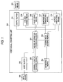
- FIG. 1 is a functional block diagram of this video signal converting apparatus.
- This video signal converting apparatus is arranged by input means 100, added information processing means 201, an input buffer 202, variable length decoding means 203, expanding means 204, coding mode judging means 205, motion predicting means 206, quadrature converting means 207, quantizing means 208, variable length coding means 209, an output buffer 210, and output means 300.
- this apparatus is featured by such a fact that while information contained in a compressed video signal inputted into this apparatus is utilized, a process operation for coding this video signal in the compression format is carried out in a high speed, or an image quality of the coded signal is increased. It should also be noted that the process operation shown in Fig. 2 does not contain this featured process operation. This featured process operation will be later explained more in detail. As indicated in Fig. 2, this apparatus executes the converting process operation of the compressed video signal in the next process flow.
- this added information processing means 201 is to control a process operation of producing an output stream by using a feature amount of an input stream, namely to control a coding process operation.
- a coding mode of an input stream is utilized, a coding mode of a relevant portion of an output frame is determined.
- a coding mode indicates a coding method, for instance, when a video signal is compressed within frame (intra)/between frames (inter), or compressed between frames, a check is made as to whether or not subtraction information and/or motion vector are used.
- Figs. 3A and 3B are structural diagrams for showing the added information processing means 201 which utilizes a coding mode of an input stream.
- Fig. 3A is a structural diagram of the added information processing means 201 capable of only determining a coding mode in the unit of a macroblock
- Fig. 3B is a structural diagram for indicating the added information processing means 201 capable of coding modes in the unit of a macroblock and also in the unit of a picture.
- Fig. 4A is a flow chart for describing a process operation executed when a coding mode is determined in the unit of a macroblock
- Fig. 4B is a flow chart for explaining a process operation executed when an inter/intra-coding mode is determined in the unit of a picture in addition to the coding mode in the unit of the macroblock.
- Fig. 4A indicates such a process operation corresponding to the structure of Fig. 3A
- Fig. 4B shows a process operation corresponding to the structure of Fig. 3B.
- FIG. 4A A description will now be made of a process flow operation shown in Fig. 4A. As indicated in Fig. 4A, a determining process operation of a coding mode in the unit of a macroblock is carried out.
- the process operation required to judge a coding mode of a non-compressed moving picture as the intra coding mode may be omitted when this non-compressed moving picture is coded, resulting in a high speed processing operation.
- the coding mode judging means 205 calculates a difference between this non-compressed moving picture and a reference image (reference picture), and judges the coding mode of this non-compressed moving picture as the intra coding mode when this subtraction is large.
- the coding mode judging process operation may be reduced by selecting/utilizing such information that the present macroblock is the same as the macroblock located at the same position of the preceding frame ----???
- the reduction of the coding mode judging process operation may be realized by omitting such a process operation that when a non-compressed moving picture is coded, a coding mode of this non-compressed moving picture is judged as a macroblock coding mode without a code. That is, in this required process operation, the coding mode judging means 205 calculates a difference between a present frame and a preceding frame, and judges the present macroblock as a macroblock without code when this difference is sufficiently small.
- a determining process operation of a coding mode including a coding mode determining process operation in the unit of a picture is carried out.
- the process operations for acquiring the macroblock coding mode and determining the coding mode thereof are identical to those of Fig. 4A except that the coding mode is stored in the coding mode storing means 20102.
- the process operations shown in Fig. 4B is featured by such that while the macroblock coding modes of the input stream for 1 picture are stored, the picture coding mode of the output stream is determined from the trend of the macroblock coding modes for 1 picture.
- the coding mode of the MPEG-4 containing also the information about the intra/inter coding modes in the unit of the picture can be properly determined from the compressed video signal by the H.261-recommended format having no such information about the intra/inter coding modes in the unit of the picture with a small number of process operations.
- a second utilization example of the added information utilizes a coding mode.
- a major different point of this second utilization example of the added information is given as follows:
- the macroblock coding mode of the output stream owns the same value as that of the coding mode of the input stream.
- a macroblock coding mode of an output stream may be set to a coding mode other than the coding mode of the input stream based upon a macroblock coding mode of a past frame of the output stream.
- Fig. 5 is a functional block diagram for indicating an internal arrangement of the added information processing means 201 used in this second utilization example. As indicated in Fig. 5, the added information processing means 201 for this second utilization example is featured by employing a coding mode history storing means 20103, as compared with the added information processing means 201 for the first utilization example.
- the process operation executed in the added information processing means 201 for this second utilization example is realized by adding the process operations (see Fig. 3A) of the first added information processing unit 201 to a coding mode history storing process operation and a coding mode history referring process operation.
- process operations see Fig. 3A
- the explanations about the process operations similar to those of the first utilization example are omitted, and a detailed explanation will be made of both the coding mode history storing process operation and the coding mode history referring process operation.
- the coding mode history information is such information for indicating how many microblocks for plural pictures are inter-coded after each of macroblocks within 1 picture has been intra-coded.
- This coding mode history information is stored in the coding mode history storage means 20103, and may be read, if required.
- Fig. 6 represents an example of the coding mode history information. As shown in Fig. 6, the coding mode history information is arranged by an array of numeral value information in which a total number of macroblocks within 1 picture constitutes an element number. Each of these numeral values indicates how many macroblocks for plural pictures are inter-coded after a macroblock located at a corresponding position has been finally intra-coded.
- This process operation is such a process operation which is executed subsequent to the coding mode acquiring/determining process operation (namely, process operation shown in Fig. 3A).
- Fig. 7(A) there is shown a process flow operation including the coding mode acquiring/determining process operation.
- the coding mode history storing process operation is executed in accordance with the following flow operation:
- the information for indicating how may pictures for plural pictures are inter-coded after the information has been finally intra-coded.
- This coding mode history referring process operation is such a process operation that in response to a request issued from the coding mode judging means 205, the coding mode history information is supplied to the coding mode judging means 205.
- Fig. 7(B) is a flow chart for describing a process flow operation executed in the coding mode history referring process operation. As indicated in Fig. 7(B), this coding mode history referring process operation is executed in accordance with the below-mentioned process flow operation.
- the coding mode is determined by utilizing the coding mode information of the input stream.
- the determined coding mode is stored as the history information. Accordingly, it is possible to improve the image quality of the output stream without largely increasing the processing amount.
- a third utilization example corresponds to such a utilization example that a process amount of a motion prediction process operation required to code an output stream by utilizing a motion vector of an input stream can be reduced.
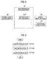
- Fig. 8 is a functional block diagram for representing an internal arrangement of the added information processing means 201 which utilizes a motion vector of an input stream as added information.
- a motion vector analyzing means 20104 acquires the motion vector of the input stream, and selects/processes the acquired information as such information which may be utilized by the motion predicting means 206.
- Fig. 9 is a flow chart for describing a process flow operation of the added information processing means 201 in this third utilization example. As indicated in Fig. 9, in this third utilization example, the motion vector information is utilized in accordance with the following process flow:
- the motion prediction mode with a in-loop filter, which uses an image formed by processing a reference image by a low-pass filter so as to predict motion.
- this motion prediction mode is not conducted in the MPEG format such as the MPEG-4 format.
- the motion vector analyzing means shifts the acquired motion vector along both the longitudinal and lateral directions by a half pixel to output such a pixel-shifted vector.
- the motion vector shifted in the unit of a half pixel in the MPEG may be obtained by averaging the adjoining pixels to produce the reference image so as to predict the motion.
- a similar effect achieved by the in-loop filter in the H.261-recommended format can be essentially obtained.
- the motion vector value of the input stream may be set to such a value which can be utilized in the motion prediction of the output stream.
- the motion vector information which has been processed in the above-explained manner may not be limited to a range of the motion vector of the output stream.
- the motion vector information is outputted in combination with such information for indicating that the relevant motion vector information cannot be directly utilized.
- the motion vector analyzing means 20104 processes the acquired motion vector in accordance with the sort of the input/output streams.
- the motion predicting means 206 determines a final motion vector of the output stream by utilizing the information about the motion vector outputted by the motion vector analyzing means 20104. There are two different sorts of methods for determining a final motion vector.
- the given motion vector information is directly used as the motion vector while the motion vector is not newly searched.
- another motion vector located within a range at the shortest distance from the given motion vector is used as the motion vector.
- a motion vector is searched to thereby acquire a final motion vector.
- a motion vector is searched while using as a reference, a point within a range located at the shortest distance from the given motion vector information.
- the first determining method is featured by that the motion prediction process operation which, generally speaking, requires the largest process amount when the coding operation is carried out is completely deleted, and therefore, the process operation can be largely reduced.
- the second determining method is featured by that the motion prediction can be realized in higher precision by performing a small amount of motion searching process operation. Thus, the process operation can be reduced without deteriorating the image quality.
- the macroblock having the motion vector in the input stream is inter-coded even in the output stream.
- the coding mode of the relevant macroblock may be intra-coded.
- the process amount can be largely deleted, and also the deterioration in the image quality can be reduced.
- a fourth utilization example is realized by that while a motion vector is utilized as added information, a motion prediction process operation executed during coding operation is reduced.
- a major different point of this fourth utilization example from the previous third utilization is given as follows. That is to say, when a motion vector is processed, a degree of accuracy (reliability) of motion vector information to be outputted is outputted, depending upon a magnitude of differential information of the relevant macroblock.
- a motion vector having a high degree of accuracy may be directly utilized without further predicting motion, and/or as to another motion vector having a low degree of accuracy, a motion vector may be searched while broadening a search range. Therefore, the process amounts can be more effectively distributed.
- a high image-quality conversion can be realized by using the same process amount.
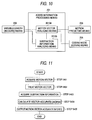
- Fig. 10 is a functional block diagram for showing an internal arrangement of the added information processing means 201 in this fourth utilization example.
- the internal arrangement of the added information processing means 201 according to this fourth utilization example is made by adding a subtraction information analyzing means 20105 to the above-explained added information processing means of the third utilization example.
- the subtraction information analyzing means 20105 acquires subtraction information corresponding to a motion vector of an acquired input stream, calculates a magnitude of this acquired subtraction information, and then outputs such information for indicating a degree of accuracy of a motion vector corresponding to the motion vector analyzing means 20104 in response to the calculation result.
- Fig. 11 is a flow chart for describing a process flow operation executed in the added information processing means 201 in this fourth utilization example. As indicated in Fig. 11, in this fourth utilization example, both a motion vector and subtraction information are utilized in the following process flow operations:
- a featured process operation of this fourth utilization example is such a process operation (defined at step 5404) for calculating the accurate degree of the motion vector from the subtraction information.
- the subtraction information contained in the input stream corresponds to such information obtained by DCT (discrete cosine transform)- transforming a subtraction component between a pixel value of the relevant macroblock and a pixel value of a macroblock of a reference image located at a position moved by the corresponding motion vector.
- this subtraction information is converted into a single value, and an accurate degree is determined by judging as to whether or not this value is smaller than a certain reference value. As this single value, there are two methods.
- one method is to utilize a summation of absolute values of DCT coefficient values within a macroblock.
- the other method is to inverse-DCT-trans form the subtraction information, and thereafter calculate an absolute value and a mean square error. Even when any one of these methods is employed, the larger the calculation result becomes, the lower the accurate degree of the vector becomes. Conversely, the smaller the calculation result becomes, the higher the accurate degree of the vector becomes.
- the motion predicting means 206 subdivides a process operation into more than two sorts of process operations in response to the accurate degree of the vector.
- Fig. 12 is a flow chart for explaining an example of a motion predicting process operation in response to the accurate degree of the vector.
- the motion predicting means 206 utilizes the accurate degree of the vector as follows:
- the coding mode judging means 205 subdivides a coding mode into more than two sorts of coding modes in response to the accurate degree of the vector.
- Fig. 13 is a flow chart for explaining an example of a coding mode judging process operation in response to the accurate degree of the vector.
- the coding mode judging means 205 utilizes the accurate degree of the vector as follows:
- the coding mode judging means 205 can precisely judge the coding mode, while executing substantially no process operation.
- the inter-frame compression format is used as moving picture compression formats including the H.261-recommended format and the MPEG-4 format.
- This compression format is performed in such a manner that a picture to be coded indicates a resembling position based on a motion vector from either a forward picture or a backward picture, and this picture together with a subtraction between the own picture and the relevant picture are coded.
- at least pictures (intra-picture) constituting a reference, all of which are intra-frame-compressed, are required in the beginning.
- the H. 261-recommended format there are many conditions such that macroblocks which are partially intra-coded are mixed with an intra-frame-compressed picture. This picture cannot be utilized as the first reference picture to be coded. Since the H. 261-recommended format does not contain such a code indicating that the entire picture is intra-coded due to the syntax thereof, the following confirmation is required in order to recognize that the overall picture has been intra-coded. That is, the coding modes of all of the microblocks contained in the picture are acquired, and it is required to confirm that all of the acquired coding modes are equal to the intra-coding mode.
- the basically-caused process delay is reduced up to 1 macroblock by employing the below-mentioned method.
- This process delay reducing method may be realized by executing the following process operation in the unit of the macroblock without storing an input stream for 1 picture, which should be transferred/coded.
- This process operation is to detect a first intra-picture when the input stream to be transferred/coded is entered into this apparatus.
- this fifth utilization example until a first intra-picture contained in an input stream is detected, all of macroblocks of an output stream are intra-coded irrespective of such a fact as to whether or not each macroblock of the input stream is actually intra-coded.
- the actual coding mode of the input stream is stored in the unit of 1 picture. Then, when the entry of the input stream for 1 picture and the production of the output stream are accomplished, a judgement is made as to whether or not the processed picture corresponds to an intra-picture.
- FIG. 5 A description will now be made of an internal arrangement of the added information processing means 201 and operations thereof, which executes the above-explained process operation in this fifth utilization example.
- the internal arrangement of the added information processing means 201 in this fifth utilization example is similar to that of the second utilization example, and is indicated by the functional block diagram of Fig. 5.
- a process flow operation by the added information processing means 201 when the normal coding operation is carried out is similar to that of the second utilization example, and is indicated in Fig. 4 and Fig. 7. Accordingly, in this fifth utilization example, an intra-picture detecting process operation which constitutes a feature of this fifth utilization example will now be explained in detail.
- a data structure of coding mode history information used in this fifth utilization example is identical to that of the coding mode history information of the second utilization example. Only a different point between these second and fifth utilization examples is given as follows. That is, in the second utilization example, the possible values of the respective elements of the coding mode history information are only positive numbers. To the contrary, in this fifth utilization example, these possible values are also negative numbers. It should be noted that in the case of a negative number, this negative number does not own a similar meaning to that of a positive number, but is utilized as one sort of code indicative of such a condition of a coding mode of each macroblock. As a consequence, as this negative number, any values may be employed. In this fifth utilization example, two sorts of negative numbers are employed, namely "-1" and "-2".
- Fig. 14 is a flow chart for describing a process flow operation of the intra-picture detecting process operation executed in this fifth utilization example. As shown in Fig. 14, the intra picture is detected in accordance with the following flow operation in this fifth utilization example.
- the picture coding mode is continuously set to the intra-coding mode.
- the process delays for more than 1 picture which are conventionally induced in the compression format transforming process operation can be basically reduced up to the process delays for 1 macroblock.
- the output stream is produced by utilizing the added information having the input stream.
- the calculation amount can be reduced, the deterioration in the image quality when the output stream is produced can be reduced, and furthermore, the process delays required to execute the stream transforming process operation can be reduced.
- the H.261-recommended format is employed as the input stream and the MPEG-4 format is used as the output stream in this embodiment.
- the process operations and the arrangement of the apparatus as explained in this first embodiment may be readily applied to even such a case that both the input stream and the output stream are compressed by other different formats.
- This video signal converting apparatus converts a video signal which is compressed by the H.261-recommended format into a video signal which is compressed by the MPEG-4-visual format. It should be understood that the video signal converting apparatus according to this second embodiment is functionally equal to the video signal converting apparatus as previously explained in the first embodiment.
- a feature of the video signal converting apparatus according to the second embodiment is to own such a function capable of using a DCT (discrete cosine transform) coefficient contained in an input stream without being inverse-DCT transformed.
- DCT discrete cosine transform
- Fig. 15 is a functional block diagram of this video signal converting apparatus.
- the arrangement of this second video signal apparatus shown in Fig. 15 is substantially identical to that of the video signal converting apparatus according to the first embodiment, shown in Fig. 1.
- the second video signal converting apparatus owns the following different point from that of the first video signal converting apparatus. That is to say, the added information processing means 201 employed in this second video signal converting apparatus is newly connected to the expanding means 204, the quantizing means 208, and the variable length coding means 209.
- the process operation shown in Fig. 16 is a process operation in such a case that the DCT coefficient of the input stream is utilized in a maximum efficiency, which constitutes a featured point of this second video signal processing apparatus.
- the process operation explained in this second embodiment may be readily combined with the various process operations executed in the video signal converting apparatus as explained in the first embodiment.
- this video signal converting apparatus executes the converting (transforming) process operation of the compressed video signal in accordance with the below-mentioned flow operations:
- a quantizing matrix (otherwise information corresponding to quantizing matrix) can be arbitrarily set
- a quantizing value of an input stream can be directly used by reusing a quantizing matrix (otherwise information corresponding to quantizing matrix), which is like an MPEG format.
- Fig. 17 is a flow chart for explaining an algorithm used to determine a quantizing value of an output stream, and also a quantizing matrix when this quantizing matrix can be set.
- quantizing matrix all of information equivalent to the quantizing matrix in the MPEG format will be referred to as a "quantizing matrix.”
- this video signal converting apparatus determines both a quantizing value and a quantizing matrix in accordance with the below-mentioned flow operation:
- the quantizing values may be varied in accordance with the general algorithm for controlling the quantizing value in the following case. That is, when the quantizing/coding operation are carried out based upon the quantizing matrix and the quantizing value determined by the above-explained algorithm, the coding amount of the output stream becomes larger than the target coding amount.
- this video signal converting apparatus can largely reducing the total processing operations for the DCT transform, the inverse DCT transform, the quantization, and the dequantization, so that the video signal can be converted in high speeds. Furthermore, as to the intra-coded macroblocks, both the inverse DCT transform and the DCT transform are not executed during the intermediate process step, and also the quantization is not again carried out. As a result, the errors caused by performing the DCT transform and the quantization can be reduced, and the high quality image can be obtained.
- the H.261-recommended format is employed as the input stream and the MPEG-4 format is used as the output stream in this embodiment.
- the process operations and the arrangement of the apparatus as explained in this second embodiment may be readily applied to even such a case that both the input stream and the output stream are compressed by other different formats.
- This video signal converting apparatus converts a video signal which is compressed by the H.261-recommended format into a video signal which is compressed by the MPEG-4-visual format. It should be understood that the video signal converting apparatus according to this third embodiment may achieve a specific effect in the case that a video signal having an image size known as a CIF (Common Interface Format) is used as either an input stream or an output stream.
- the video signal converting apparatus according to this third embodiment is similar to the above-explained video signal converting apparatus according to the first embodiment. However, this third embodiment owns the following different point. That is, any one of the input stream and the output stream, or both the these input/output streams use the image size of the CIF.
- Fig. 18 is a diagram for representing macroblocks contained in 1 picture having a CIF image size, and a coding order of these macroblocks in the case that the macroblocks are coded by the MPEG-4 format.
- a minimum region surrounded by a dotted line of Fig. 18 indicates a single macroblock.
- 396 pieces of macroblocks constituted by 22 macroblocks (longitudinal direction) ⁇ 18 macroblocks (lateral direction) are contained in 1 picture having an image size of CIF.
- numerals appearing in the macroblocks shown in Fig. 18 indicate orders by which the relevant macroblocks are coded in the pictures.
- the macroblocks are coded in this order from an upper left end to a right direction.
- Fig. 19 is a diagram for representing macroblocks contained in 1 picture having a CIF image size, and a coding order of these macroblocks in the case that the macroblocks are coded by the H.261-recommended format. Also, in the H.261-recommended format, a total number of macroblocks contained in 1 picture having an image size of CIF is equal to that of the MPEG-4 format. However, the coding order used in the H.261-recommended format is different from that used in the MPEG-4 format. A minimum region surrounded by a dotted line of Fig. 19 indicates a single macroblock.
- a laterally-elongated region surrounded by a solid line within a picture represents a GOB (Group Of Block).
- GOB Group Of Block
- 33 pieces of macroblocks are contained in each of GOBs.
- 12 pieces of GOBs are contained in 1 picture.
- macroblocks are coded in the unit of GOB.
- coding orders of macroblocks are established in such a manner that after macroblocks contained in one GOB are continuously coded, macroblocks contained in the next GOB are continuously coded. Concretely speaking, in Fig.
- the GOB symbolized as "A” is firstly codeded, and the remaining GOBs are successively coded in this order of an alphabet, and finally, the GOB symbolized as "L” is coded.
- the macroblocks contained in the respective GOBs are sequentially coded from the upper left end to the right direction, and the macroblock (lower right end) contained in the GOB symbolized as "L” is coded.
- This utilization example is useful in the compression format conversion from the H.261-recommended format into the MPEG-4 format in the image data having the CIF image size, and contains the above-explained feature.
- a basic idea of reducing a delay by way of this sixth utilization example is identical to the basic idea of reducing the process delay in the video converting apparatus as shown in the fifth utilization example according to the first embodiment.
- This video coding apparatus owns the following different point from the above-explained video signal converting apparatus. That is, even in such a case that coding orders of macroblocks contained in a picture are different from each other between an input stream and an output stream, this video coding apparatus is equipped with a process operation and means, which can realize a process delay less than 1 picture.
- Fig. 20 is a functional block diagram for indicating the internal structure of this apparatus.
- the structural arrangement of this video coding apparatus is similar to the structural arrangement of the video signal converting apparatus according to the first embodiment.
- a structural different point of this video coding apparatus is given by that an image buffer 211 is provided in the video signal converting unit 200.
- the function of the image buffer 211 is as follows: This image buffer 211 stores thereinto information of a macroblock of an input stream which is supplied from either the expanding means 204 or the added information processing means 201.
- the image buffer 211 supplies the stored information of the macroblocks to either the coding mode judging means 205 or the added information processing means 201 in such an order required to produce an output stream.
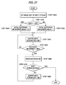
- Fig. 21 is a flow chart for showing a process flow operation of the image buffer 211 employed in this video coding apparatus. As indicated in Fig. 21, the image buffer 211 executes a process flow operation as flows:
- the input stream is compressed in the H.261-recommended format whereas the output stream is compressed in the MPEG-4 format.
- the above-described process operation of the image buffer 211 may be carried out in a similar manner even in such a case that the compression formats for the input stream and the output stream are reversed while involving the macroblock number "MBinit".
- the principle process delay can be considerably shorten, as compared with the conventional 1 picture, even in such a format conversion that the coding orders of the macroblocks are different from each other.
- a method for judging a coding mode executed in this seventh utilization example is such a judging method performed by utilizing a coding mode of an input macroblock corresponding thereto.
- This judging method is similar to the first to second utilization examples of the added information according to the first embodiment.
- a major different point of this seventh utilization example from the utilization examples described in the first embodiment is given as follows. Even in such a compression format converting operation between streams having different sizes, for instance, an input stream is a CIF size and an output stream is a QCIF size, a coding mode can be effectively judged. Accordingly, in this seventh utilization example, the sizes of the streams are given as follows. That is, the input stream is the H.261-recommended format of the CIF size, and the output stream is the MPEG-4 format of the QCIF size.
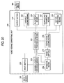
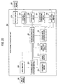
- Fig. 22 is a functional block diagram for indicating the internal structure of this apparatus.
- the structural arrangement of this video coding apparatus is similar to the structural arrangement of the video coding apparatus shown in Fig. 20.
- An image modifying means 212 is additionally provided with the arrangement of the video coding apparatus indicated in Fig. 20.
- an added information processing means 201 is similar to the arrangement shown in Fig. 5.
- FIG. 23 An overall process flow operation of this video coding apparatus is described in a flow chart shown in Fig. 23.
- this overall process flow operation own a different process operation from that of Fig. 2. That is, only an image reducing process operation as defined at a step 3050 is additionally provided.
- This image reducing process operation corresponds to such a process operation that an image of an input stream is reduced by 1/2 along both a longitudinal direction and a lateral direction in the unit of 1 macroblock, 4 macroblocks, or 1 picture. Since the known image reducing method may be introduced as this reducing process operation and this image reducing method does not constitute a major subject of this seventh utilization example, a detailed explanation thereof is omitted. It should also be noted that as a process operation of an image buffer, the process operation shown in Fig. 21 may be employed.
- This video coding apparatus is featured by such a method for utilizing coding mode history information realized by both the added information processing means 201 and the coding mode judging means 205.
- Fig. 24 is a flow chart for describing a process operation for judging a macroblock coding mode executed in this seventh utilization example.
- a coding mode as a coding mode, only such a judgement process is employed so as to judge whether a relevant macroblock is intra-coded, or coded by other coding modes than this intra coding mode.
- a decision of a coding mode such as non-code mode may be additionally provided.
- a coding mode with respect to a single macroblock is determined in accordance with the following flow operation.
- the threshold value used in the step 20000 may be arbitrarily set. This threshold value is set with respect to a total number of the macroblocks which have been inter-coded in the past. For example, in such a case that this threshold value is set to a total number (99 in this seventh utilization example) of macroblocks contained in 1 picture of the output stream, the following useful effect may be achieved when 1 macroblock per 1 picture is always intra-coded in the coding order within the input stream. That is, also in the output stream, the respective macroblocks are uniformly intra-coded. Also, when the value of this threshold value is increased, the appearing frequency of the macroblocks to be intra-coded is lowered, and the coding amount of the output stream is statically decreased. Conversely, when the value of this threshold value is decreased, the coding amount of the output stream is statically increased.
- the coding mode of the output stream can be determined by utilizing the coding mode of the input stream. Since the coding mode can be judged without executing the process operation in which the difference between the present picture and the preceding picture is acquired in each of the macroblocks, the total processing amount can be reduced.
- the compression format converting operation may be carried out with having such a delay amount smaller than 1 picture.
- the processing amount required to determine the coding mode can be reduced.
- the decoding operation for the input stream and also the re-coding operation can be reduced. Also, the calculation amount required for the converting operation can be reduced.
Landscapes
- Engineering & Computer Science (AREA)
- Multimedia (AREA)
- Signal Processing (AREA)
- Compression Or Coding Systems Of Tv Signals (AREA)
Applications Claiming Priority (2)
| Application Number | Priority Date | Filing Date | Title |
|---|---|---|---|
| JP4621799A JP2000244921A (ja) | 1999-02-24 | 1999-02-24 | 映像符号化方法および装置 |
| JP4621799 | 1999-02-24 |
Publications (3)
| Publication Number | Publication Date |
|---|---|
| EP1032213A2 true EP1032213A2 (fr) | 2000-08-30 |
| EP1032213A3 EP1032213A3 (fr) | 2004-04-28 |
| EP1032213B1 EP1032213B1 (fr) | 2006-04-26 |
Family
ID=12740950
Family Applications (1)
| Application Number | Title | Priority Date | Filing Date |
|---|---|---|---|
| EP20000103728 Expired - Lifetime EP1032213B1 (fr) | 1999-02-24 | 2000-02-22 | Procédé et dispositif de transcodage vidéo |
Country Status (4)
| Country | Link |
|---|---|
| US (1) | US6798837B1 (fr) |
| EP (1) | EP1032213B1 (fr) |
| JP (1) | JP2000244921A (fr) |
| DE (1) | DE60027495T2 (fr) |
Cited By (8)
| Publication number | Priority date | Publication date | Assignee | Title |
|---|---|---|---|---|
| US6438168B2 (en) | 2000-06-27 | 2002-08-20 | Bamboo Media Casting, Inc. | Bandwidth scaling of a compressed video stream |
| EP1838105A1 (fr) | 2006-02-24 | 2007-09-26 | Samsung Electronics Co., Ltd. | Procédé et appareil de transcodage de vidéo |
| EP1370087A4 (fr) * | 2002-01-07 | 2008-02-27 | Mitsubishi Electric Corp | Appareil de codage d'images animees et appareil de decodage d'images animees |
| EP2124455A4 (fr) * | 2007-03-14 | 2010-08-11 | Nippon Telegraph & Telephone | Procédé et dispositif de recherche de vecteur de mouvement, programme apparenté, et support d'enregistrement ayant enregistré le programme |
| US8265142B2 (en) | 2007-03-14 | 2012-09-11 | Nippon Telegraph And Telephone Corporation | Encoding bit-rate control method and apparatus, program therefor, and storage medium which stores the program |
| CN101026758B (zh) * | 2006-02-24 | 2012-12-05 | 三星电子株式会社 | 视频代码转换方法和设备 |
| US9161042B2 (en) | 2007-03-14 | 2015-10-13 | Nippon Telegraph And Telephone Corporation | Quantization control method and apparatus, program therefor, and storage medium which stores the program |
| US9455739B2 (en) | 2007-03-14 | 2016-09-27 | Nippon Telegraph And Telephone Corporation | Code amount estimating method and apparatus, and program and storage medium therefor |
Families Citing this family (25)
| Publication number | Priority date | Publication date | Assignee | Title |
|---|---|---|---|---|
| US7003035B2 (en) * | 2002-01-25 | 2006-02-21 | Microsoft Corporation | Video coding methods and apparatuses |
| US7596179B2 (en) * | 2002-02-27 | 2009-09-29 | Hewlett-Packard Development Company, L.P. | Reducing the resolution of media data |
| US20040001546A1 (en) | 2002-06-03 | 2004-01-01 | Alexandros Tourapis | Spatiotemporal prediction for bidirectionally predictive (B) pictures and motion vector prediction for multi-picture reference motion compensation |
| US7154952B2 (en) | 2002-07-19 | 2006-12-26 | Microsoft Corporation | Timestamp-independent motion vector prediction for predictive (P) and bidirectionally predictive (B) pictures |
| US8218634B2 (en) * | 2005-01-13 | 2012-07-10 | Ntt Docomo, Inc. | Nonlinear, in-the-loop, denoising filter for quantization noise removal for hybrid video compression |
| US8588513B2 (en) * | 2005-07-18 | 2013-11-19 | Broadcom Corporation | Method and system for motion compensation |
| EP2080377A2 (fr) * | 2006-10-31 | 2009-07-22 | THOMSON Licensing | Procédé et appareil pour manipuler des flux binaires |
| JP5166435B2 (ja) * | 2006-12-11 | 2013-03-21 | トムソン ライセンシング | 画像符号化方法及び係る方法を実現する装置 |
| US8254455B2 (en) | 2007-06-30 | 2012-08-28 | Microsoft Corporation | Computing collocated macroblock information for direct mode macroblocks |
| JP4922138B2 (ja) * | 2007-11-20 | 2012-04-25 | 株式会社東芝 | 動画像符号化装置及び動画像符号化方法 |
| CN101897187A (zh) * | 2007-12-11 | 2010-11-24 | 汤姆森特许公司 | 用于在分发链内进行代码转换的方法和系统 |
| US8611423B2 (en) * | 2008-02-11 | 2013-12-17 | Csr Technology Inc. | Determination of optimal frame types in video encoding |
| US8326075B2 (en) | 2008-09-11 | 2012-12-04 | Google Inc. | System and method for video encoding using adaptive loop filter |
| US8189666B2 (en) | 2009-02-02 | 2012-05-29 | Microsoft Corporation | Local picture identifier and computation of co-located information |
| US8498330B2 (en) * | 2009-06-29 | 2013-07-30 | Hong Kong Applied Science and Technology Research Institute Company Limited | Method and apparatus for coding mode selection |
| US8283152B2 (en) | 2009-08-28 | 2012-10-09 | Cj Cheiljedang Corporation | Microorganism producing O-acetyl-homoserine and the method of producing O-acetyl-homoserine using the microorganism |
| US8780971B1 (en) | 2011-04-07 | 2014-07-15 | Google, Inc. | System and method of encoding using selectable loop filters |
| US8781004B1 (en) | 2011-04-07 | 2014-07-15 | Google Inc. | System and method for encoding video using variable loop filter |
| US8780996B2 (en) | 2011-04-07 | 2014-07-15 | Google, Inc. | System and method for encoding and decoding video data |
| US8885706B2 (en) | 2011-09-16 | 2014-11-11 | Google Inc. | Apparatus and methodology for a video codec system with noise reduction capability |
| US9131073B1 (en) | 2012-03-02 | 2015-09-08 | Google Inc. | Motion estimation aided noise reduction |
| US9344729B1 (en) | 2012-07-11 | 2016-05-17 | Google Inc. | Selective prediction signal filtering |
| US10102613B2 (en) | 2014-09-25 | 2018-10-16 | Google Llc | Frequency-domain denoising |
| US11019365B2 (en) | 2015-07-30 | 2021-05-25 | Zhejiang Dahua Technology Co., Ltd. | Methods and systems for image compression |
| JP6574148B2 (ja) * | 2016-07-13 | 2019-09-11 | Kddi株式会社 | トランスコードシステム、トランスコード方法、コンピュータ可読記録媒体および符号化装置 |
Family Cites Families (17)
| Publication number | Priority date | Publication date | Assignee | Title |
|---|---|---|---|---|
| DE69322769T2 (de) * | 1992-03-03 | 1999-07-22 | Kabushiki Kaisha Toshiba, Kawasaki, Kanagawa | Koder für zeitveränderliche bilder |
| US5614952A (en) * | 1994-10-11 | 1997-03-25 | Hitachi America, Ltd. | Digital video decoder for decoding digital high definition and/or digital standard definition television signals |
| JP3085024B2 (ja) | 1993-06-01 | 2000-09-04 | 松下電器産業株式会社 | 画像再圧縮器及び画像記録装置 |
| DE4416967A1 (de) * | 1994-05-13 | 1995-11-16 | Thomson Brandt Gmbh | Verfahren und Vorrichtung zur Transcodierung von Bitströmen mit Videodaten |
| ATE369700T1 (de) | 1994-06-17 | 2007-08-15 | Snell & Wilcox Ltd | Videokompression |
| US5652849A (en) * | 1995-03-16 | 1997-07-29 | Regents Of The University Of Michigan | Apparatus and method for remote control using a visual information stream |
| GB9608271D0 (en) | 1996-04-22 | 1996-06-26 | Electrocraft Lab | Video compession |
| US5709473A (en) * | 1996-05-13 | 1998-01-20 | General Motors Corporation | Temperature sensor |
| JPH1051766A (ja) | 1996-08-05 | 1998-02-20 | Mitsubishi Electric Corp | 画像符号化データ変換装置 |
| US5969750A (en) * | 1996-09-04 | 1999-10-19 | Winbcnd Electronics Corporation | Moving picture camera with universal serial bus interface |
| SE515535C2 (sv) | 1996-10-25 | 2001-08-27 | Ericsson Telefon Ab L M | En transkoder |
| US5870146A (en) * | 1997-01-21 | 1999-02-09 | Multilink, Incorporated | Device and method for digital video transcoding |
| US6226328B1 (en) * | 1998-05-01 | 2001-05-01 | Boom Corporation | Transcoding apparatus for digital video networking |
| US6434197B1 (en) * | 1999-01-07 | 2002-08-13 | General Instrument Corporation | Multi-functional transcoder for compressed bit streams |
| US6275536B1 (en) * | 1999-06-23 | 2001-08-14 | General Instrument Corporation | Implementation architectures of a multi-channel MPEG video transcoder using multiple programmable processors |
| WO2001006793A1 (fr) * | 1999-07-20 | 2001-01-25 | Koninklijke Philips Electronics N.V. | Transcodeur sans derive et procede associe |
| US6441754B1 (en) * | 1999-08-17 | 2002-08-27 | General Instrument Corporation | Apparatus and methods for transcoder-based adaptive quantization |
-
1999
- 1999-02-24 JP JP4621799A patent/JP2000244921A/ja active Pending
-
2000
- 2000-02-18 US US09/507,040 patent/US6798837B1/en not_active Expired - Lifetime
- 2000-02-22 DE DE2000627495 patent/DE60027495T2/de not_active Expired - Fee Related
- 2000-02-22 EP EP20000103728 patent/EP1032213B1/fr not_active Expired - Lifetime
Cited By (14)
| Publication number | Priority date | Publication date | Assignee | Title |
|---|---|---|---|---|
| US6438168B2 (en) | 2000-06-27 | 2002-08-20 | Bamboo Media Casting, Inc. | Bandwidth scaling of a compressed video stream |
| EP2320657A3 (fr) * | 2002-01-07 | 2011-08-31 | Mitsubishi Denki Kabushiki Kaisha | Appareil de codage et de décodage d'images en mouvement |
| EP1370087A4 (fr) * | 2002-01-07 | 2008-02-27 | Mitsubishi Electric Corp | Appareil de codage d'images animees et appareil de decodage d'images animees |
| EP2320656A3 (fr) * | 2002-01-07 | 2011-08-31 | Mitsubishi Denki Kabushiki Kaisha | Appareil de codage et de décodage d'images en mouvement |
| EP2026583A3 (fr) * | 2002-01-07 | 2011-08-31 | Mitsubishi Denki Kabushiki Kaisha | Appareil de codage et de décodage d'une image en mouvement |
| EP2320658A3 (fr) * | 2002-01-07 | 2011-08-31 | Mitsubishi Denki Kabushiki Kaisha | Appareil de codage et de décodage d'images en mouvement |
| CN101026758B (zh) * | 2006-02-24 | 2012-12-05 | 三星电子株式会社 | 视频代码转换方法和设备 |
| EP1838105A1 (fr) | 2006-02-24 | 2007-09-26 | Samsung Electronics Co., Ltd. | Procédé et appareil de transcodage de vidéo |
| EP2124455A4 (fr) * | 2007-03-14 | 2010-08-11 | Nippon Telegraph & Telephone | Procédé et dispositif de recherche de vecteur de mouvement, programme apparenté, et support d'enregistrement ayant enregistré le programme |
| US8265142B2 (en) | 2007-03-14 | 2012-09-11 | Nippon Telegraph And Telephone Corporation | Encoding bit-rate control method and apparatus, program therefor, and storage medium which stores the program |
| US8396130B2 (en) | 2007-03-14 | 2013-03-12 | Nippon Telegraph And Telephone Corporation | Motion vector search method and apparatus, program therefor, and storage medium which stores the program |
| CN101682775B (zh) * | 2007-03-14 | 2015-04-01 | 日本电信电话株式会社 | 运动矢量搜索方法和装置 |
| US9161042B2 (en) | 2007-03-14 | 2015-10-13 | Nippon Telegraph And Telephone Corporation | Quantization control method and apparatus, program therefor, and storage medium which stores the program |
| US9455739B2 (en) | 2007-03-14 | 2016-09-27 | Nippon Telegraph And Telephone Corporation | Code amount estimating method and apparatus, and program and storage medium therefor |
Also Published As
| Publication number | Publication date |
|---|---|
| DE60027495D1 (de) | 2006-06-01 |
| US6798837B1 (en) | 2004-09-28 |
| DE60027495T2 (de) | 2006-09-28 |
| EP1032213A3 (fr) | 2004-04-28 |
| JP2000244921A (ja) | 2000-09-08 |
| EP1032213B1 (fr) | 2006-04-26 |
Similar Documents
| Publication | Publication Date | Title |
|---|---|---|
| US6798837B1 (en) | Video coding method and video coding apparatus | |
| US6535556B1 (en) | Apparatus and method for encoding images and medium in which image encoding program has been recorded | |
| CN1192632C (zh) | 可变比特率视频编码方法和相应的视频编码器 | |
| US6108039A (en) | Low bandwidth, two-candidate motion estimation for interlaced video | |
| JP4344476B2 (ja) | 3:2プルダウンビデオ情報を含むビデオ情報ストリームの適応エンコーディング速度制御を実行する方法および装置 | |
| US7050499B2 (en) | Video encoding apparatus and method and video encoding mode converting apparatus and method | |
| EP1551186A1 (fr) | Appareil de codage avec convertisseur de résolution | |
| US7876829B2 (en) | Motion compensation image coding device and coding method | |
| JPH1146364A (ja) | 動き補償符号化装置、復号化装置、符号化方法及び復号化方法 | |
| US6192078B1 (en) | Motion picture converting apparatus | |
| JPH08111870A (ja) | 画像情報の再符号化方法及び装置 | |
| US20040105501A1 (en) | Encoded-data converting apparatus and method for the same | |
| JP4120934B2 (ja) | 画像処理装置および画像処理方法、記録媒体、並びに、プログラム | |
| JP4826533B2 (ja) | 画像処理装置および画像処理方法、プログラム、並びに、記録媒体 | |
| JP3200199B2 (ja) | 動画像圧縮符号化方法 | |
| JP3428332B2 (ja) | 画像符号化方法及び装置、並びに画像伝送方法 | |
| JP3542911B2 (ja) | 動画圧縮装置 | |
| JPH0951538A (ja) | 画像信号の符号化方法 | |
| JPH10108197A (ja) | 画像符号化装置、画像符号化制御方法および画像符号化制御用プログラムを記録した媒体 | |
| JPH11308622A (ja) | 動画像再符号化装置 | |
| KR100589112B1 (ko) | 엠펙-제이펙 공용 부/복호화 시스템 | |
| JP4539028B2 (ja) | 画像処理装置および画像処理方法、記録媒体、並びに、プログラム | |
| US20070153909A1 (en) | Apparatus for image encoding and method thereof | |
| JP4359273B2 (ja) | 符号化モード選択方法 | |
| JP2006121538A (ja) | 画像符号化装置、及び画像符号化方法 |
Legal Events
| Date | Code | Title | Description |
|---|---|---|---|
| PUAI | Public reference made under article 153(3) epc to a published international application that has entered the european phase |
Free format text: ORIGINAL CODE: 0009012 |
|
| AK | Designated contracting states |
Kind code of ref document: A2 Designated state(s): AT BE CH CY DE DK ES FI FR GB GR IE IT LI LU MC NL PT SE |
|
| AX | Request for extension of the european patent |
Free format text: AL;LT;LV;MK;RO;SI |
|
| PUAL | Search report despatched |
Free format text: ORIGINAL CODE: 0009013 |
|
| AK | Designated contracting states |
Kind code of ref document: A3 Designated state(s): AT BE CH CY DE DK ES FI FR GB GR IE IT LI LU MC NL PT SE |
|
| AX | Request for extension of the european patent |
Extension state: AL LT LV MK RO SI |
|
| RIC1 | Information provided on ipc code assigned before grant |
Ipc: 7H 04N 7/50 A Ipc: 7H 04N 7/26 B |
|
| 17P | Request for examination filed |
Effective date: 20040831 |
|
| 17Q | First examination report despatched |
Effective date: 20041005 |
|
| AKX | Designation fees paid |
Designated state(s): DE FR GB |
|
| GRAP | Despatch of communication of intention to grant a patent |
Free format text: ORIGINAL CODE: EPIDOSNIGR1 |
|
| GRAC | Information related to communication of intention to grant a patent modified |
Free format text: ORIGINAL CODE: EPIDOSCIGR1 |
|
| GRAS | Grant fee paid |
Free format text: ORIGINAL CODE: EPIDOSNIGR3 |
|
| GRAA | (expected) grant |
Free format text: ORIGINAL CODE: 0009210 |
|
| AK | Designated contracting states |
Kind code of ref document: B1 Designated state(s): DE FR GB |
|
| REG | Reference to a national code |
Ref country code: GB Ref legal event code: FG4D |
|
| REF | Corresponds to: |
Ref document number: 60027495 Country of ref document: DE Date of ref document: 20060601 Kind code of ref document: P |
|
| ET | Fr: translation filed | ||
| PLBE | No opposition filed within time limit |
Free format text: ORIGINAL CODE: 0009261 |
|
| STAA | Information on the status of an ep patent application or granted ep patent |
Free format text: STATUS: NO OPPOSITION FILED WITHIN TIME LIMIT |
|
| 26N | No opposition filed |
Effective date: 20070129 |
|
| PGFP | Annual fee paid to national office [announced via postgrant information from national office to epo] |
Ref country code: DE Payment date: 20090219 Year of fee payment: 10 |
|
| PGFP | Annual fee paid to national office [announced via postgrant information from national office to epo] |
Ref country code: GB Payment date: 20090217 Year of fee payment: 10 |
|
| PGFP | Annual fee paid to national office [announced via postgrant information from national office to epo] |
Ref country code: FR Payment date: 20090213 Year of fee payment: 10 |
|
| GBPC | Gb: european patent ceased through non-payment of renewal fee |
Effective date: 20100222 |
|
| REG | Reference to a national code |
Ref country code: FR Ref legal event code: ST Effective date: 20101029 |
|
| PG25 | Lapsed in a contracting state [announced via postgrant information from national office to epo] |
Ref country code: FR Free format text: LAPSE BECAUSE OF NON-PAYMENT OF DUE FEES Effective date: 20100301 |
|
| PG25 | Lapsed in a contracting state [announced via postgrant information from national office to epo] |
Ref country code: DE Free format text: LAPSE BECAUSE OF NON-PAYMENT OF DUE FEES Effective date: 20100901 |
|
| PG25 | Lapsed in a contracting state [announced via postgrant information from national office to epo] |
Ref country code: GB Free format text: LAPSE BECAUSE OF NON-PAYMENT OF DUE FEES Effective date: 20100222 |