EP1032298B1 - Behälter mit funktionsspezifischer gestaltung seines innenraums - Google Patents
Behälter mit funktionsspezifischer gestaltung seines innenraums Download PDFInfo
- Publication number
- EP1032298B1 EP1032298B1 EP99936265A EP99936265A EP1032298B1 EP 1032298 B1 EP1032298 B1 EP 1032298B1 EP 99936265 A EP99936265 A EP 99936265A EP 99936265 A EP99936265 A EP 99936265A EP 1032298 B1 EP1032298 B1 EP 1032298B1
- Authority
- EP
- European Patent Office
- Prior art keywords
- container
- insert
- container according
- wall
- heating
- Prior art date
- Legal status (The legal status is an assumption and is not a legal conclusion. Google has not performed a legal analysis and makes no representation as to the accuracy of the status listed.)
- Expired - Lifetime
Links
- 238000010438 heat treatment Methods 0.000 claims abstract description 31
- 238000001816 cooling Methods 0.000 claims abstract description 10
- 239000004033 plastic Substances 0.000 claims description 5
- 229920003023 plastic Polymers 0.000 claims description 5
- 239000000463 material Substances 0.000 claims description 4
- 239000002826 coolant Substances 0.000 claims description 2
- 239000007788 liquid Substances 0.000 claims description 2
- 230000000717 retained effect Effects 0.000 claims 2
- 230000004308 accommodation Effects 0.000 claims 1
- 229910052751 metal Inorganic materials 0.000 description 6
- 239000002184 metal Substances 0.000 description 6
- 238000009749 continuous casting Methods 0.000 description 5
- 238000005299 abrasion Methods 0.000 description 1
- 229910052782 aluminium Inorganic materials 0.000 description 1
- XAGFODPZIPBFFR-UHFFFAOYSA-N aluminium Chemical compound [Al] XAGFODPZIPBFFR-UHFFFAOYSA-N 0.000 description 1
- 235000013361 beverage Nutrition 0.000 description 1
- 230000000295 complement effect Effects 0.000 description 1
- 238000010276 construction Methods 0.000 description 1
- 230000001419 dependent effect Effects 0.000 description 1
- 238000005516 engineering process Methods 0.000 description 1
- 238000001125 extrusion Methods 0.000 description 1
- 238000005187 foaming Methods 0.000 description 1
- 238000005338 heat storage Methods 0.000 description 1
- 238000002360 preparation method Methods 0.000 description 1
- 239000007787 solid Substances 0.000 description 1
- 238000005496 tempering Methods 0.000 description 1
Images



Classifications
-
- A—HUMAN NECESSITIES
- A47—FURNITURE; DOMESTIC ARTICLES OR APPLIANCES; COFFEE MILLS; SPICE MILLS; SUCTION CLEANERS IN GENERAL
- A47B—TABLES; DESKS; OFFICE FURNITURE; CABINETS; DRAWERS; GENERAL DETAILS OF FURNITURE
- A47B88/00—Drawers for tables, cabinets or like furniture; Guides for drawers
- A47B88/40—Sliding drawers; Slides or guides therefor
- A47B88/423—Fastening devices for slides or guides
- A47B88/43—Fastening devices for slides or guides at cabinet side
Definitions
- the invention relates to a container according to the preamble of claim 1.
- a typical example of this are baking trays in an oven.
- Such systems are used, for example, when transporting food containers in insulated housings, where the good use of the available storage volume especially for thermal and therefore energetic reasons is desirable.
- heating elements for heating purposes, it is known for this purpose to place heating elements in the wall parts to integrate such a container, for example by foaming.
- a large number of containers are known, in which at least one function-specific Insert is arranged, e.g. US 4,026,351 (cooling or heating insert as a wall element in a transport container), US 4,817,582 (oven with insert), US 4,190,305 (refrigerator with insert), US 5,640,946 (steam oven with receiving insert), US 4,194,109 (trolley with insert), and US 5,732,614 (container for food preparation with bearing insert).
- the way of holding the respective insert is only subordinate; either it is only intended to total use in to position the designated functional space at a suitable location (US 4,194,109), or to anchor it firmly, e.g. using screws (US 4,190,305) as a fastener, especially when it is flat Stakes that should be kept vertical.
- Each wall element can have a different design can be selected, for example a profiled wall element be chosen that then used in the container near a side wall so that it is in profile channels supported in the walls of the container.
- a special configuration of a such a wall element can then also provide that it can be heated or cooled is designed, what the area of application of the container, in particular during transport and the storage of perishable goods such as food, food or beverages extended.
- FIG. 1 the attachment of an insert E in a container Z is shown.
- the container Z consists of bottom part B, back side RS, top part D and two side walls SW.
- E only from a rectangular frame R with two vertically extending Side parts and two horizontally extending side parts connecting these side parts.
- floors E1 ... E7 are shown on which an object G can be accommodated; for example, the one shown in FIG. cuboid-like object G similar to drawer on level E4 in the direction of the arrow in the container are inserted, the object G extends over the Levels E4, E5 and E6.
- FIG. 1 A mirror image of this and not shown in Fig. 1 is on the opposite Side wall SW of the container Z an identical insert E held so that the Container has two opposite inserts.
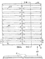
- Fig. 2 shows a view of a preferred embodiment of such Insert E, which contains ten floors E1 ... E10, spaced one above the other vertical wall element WE form what a light and inexpensive design enables, which are used in particular in a container according to FIG. 1 can.
- the wall element is supported in the region of a side wall SW Container Z between its bottom part B and top part D, which is sufficient Stability guaranteed.
- such a wall element WE is in a profile channel R1 both in the upper part D and in the bottom part B in the container Z set.
- a further depression is made within the groove R1, which together acts with a correspondingly shaped pin on the lower end face S1 and thus forms a locking element RE1 / RE2. This is particularly useful and necessary around horizontal forces occurring when objects G are inserted or removed to be introduced into the container Z without the wall element being removed from the container is pulled out.
- Such a channel can basically be located in each of the walls, for example also parallel to the rear side RS in the bottom part B and in the top part D (cover), wherever the function-specific design of the deployment requires it.
- the insert can only be used to hold objects (Fig. 2 to 4), but it can also, for example, heat or cool the interior take over the container Z (Figs. 5-10) or simply as a heating or Cooling element can be designed without a storage function (Fig. 11). Accordingly can also have multiple inserts of different functionality in one container Z find use.
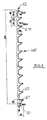
- the insert consists of an extruded profile 50, on which support elements 54 are formed, and accordingly can be used as wall element E, as shown in FIGS. 3 and 4 is shown in principle.
- a rear wall 51 parallel to the main plane of the continuous casting profile 50, which forms a front wall, which points to the inside of the container Z, held a rear wall 51, for example can be formed by a simple sheet metal part and the end face in a groove on the top and the lower end (not shown) of the turned part of the continuous casting profile can be used.
- heating element which is also used in the following, is not intended here to be understood as restricting to a certain technology of a heating element, it can be an electric heater, but it can also Heating elements or cooling elements with a liquid or gaseous medium are supplied from outside, are kept in volume V.
- Heating elements can in turn be active or passive, i.e. they can with an energy supply be connected from the outside, then it essentially comes down to the good Thermal conductivity, but they can also be used as a component with high heat storage capacity be trained to be “charged” (heated or cooled) externally and then inserted into the volume V or attached to the insert, at least the intended temperature of the interior of the container for a certain period of time to ensure about this commitment.
- this insert as shown in Fig. 5B, is sealed with a cap 53 on its end faces, it is possible without "heating element" 57 the volume itself to accommodate an outside to use supplied heating medium, which then, for example, via the indicated Bore in the cap 53 can be supplied and removed.
- FIG. 5C shows cross-sectional representations of exemplary embodiments of the support elements 54. All of the exemplary embodiments have in common that they consist of a profiling of the continuous casting profile 50, in which a correspondingly complementarily shaped Support profile is insertable, attachable or insertable.
- material for this Support profiles are either plastic or CNS (for example for the tubular profiles 513 and 515).
- Structure and material of the support profiles is in essentially determined by the type of container to be accommodated, i.e. of their Surface quality and weight in order with regard to abrasion and wear as well To achieve optimal results.
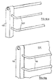
- FIG. 6 The third exemplary embodiment shown in FIG. 6 is first of all again just “only” around an insert E as a wall element for receiving the objects, here a plastic front part 63 is formed so that it has support elements 64, for example made of CNS wire, so that two ends arranged components 63 with intermediate support elements 64 a wall element form, as it is in principle in Figs. 3 and 4 is shown.
- support elements 64 for example made of CNS wire
- FIG. 6B in turn shows the further development of such an insert as a heating or Cooling element, with a first sheet metal part to form a front wall 65 and second sheet metal part to form a rear wall 66, so that a volume V arises, in which a heating element 67 described in FIG. 5 in the respectively desired Embodiment is used. Also in this embodiment leaves the "only" wall element according to FIG. 6A thus becomes a "wall and heating element" 6B refine or retrofit.
- Fig. 7 shows a fourth embodiment in which an aluminum extrusion profile as the front wall 75 is used with a profile on both sides, in one rail 78 can be inserted, which in turn is spaced apart in terms of height 74, which in turn is formed, for example, as a CNS wire bracket could be.
- the rear wall 76 is formed from a sheet metal part on the front wall is again one of the embodiments of the heating element mentioned at the beginning " 77 held.
- the connection between front wall 75 and rear wall 76 is produced by a cap 73, which is also designed as a profile part.
- the main difference between this exemplary embodiment and that explained at the outset consists of the vertical alignment of the individual components.
- FIG. 8 shows a fifth exemplary embodiment, in which the front wall 85 and rear wall 86 are formed from sheet metal parts that have a semi-cylindrical shape at the top and bottom Plastic cap 83 are completed, which is designed so that it for example can be used in the channels shown in Fig. 4.
- the support elements 84 are here inserted through the front wall 85 on its front and on its bent Attached to the back, so that here too there is a secure mounting, the heating element 87 is in turn located on the inside of the front wall 85.
- FIG. 9A and B in turn show the design of an insert only as a wall element (Fig. 9A), which is formed exclusively from wire elements 94, of which the outer form a frame which can be fixed in the channels according to FIG. 4.
- a plurality of retaining tabs 94A are attached to this frame, via which this “only” wall element again equipped with heating or cooling agents additionally or subsequently can be made from two essentially identical sheets as the front wall 95 and rear wall 96 are formed, in the interior V of which a heating element 97 is inserted is.
- the upper and lower end can be with a (not shown) Plastic element according to Figure 8A can be achieved.
- the seventh embodiment shown in FIG. 10 corresponds in its basic concept the third exemplary embodiment shown in FIG. 6, with the difference that post-shaped cylindrical holding elements 103 are provided on which the Support elements 104 are held in the form of CNS wire clips.
- a heating element as has already been illustrated in FIG. 6, so that only the front wall 105 from a sheet metal part is visible in FIG. 10B.
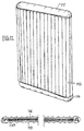
- FIG. 11 shows a wall heating element, which is formed from two extruded profiles that have a front wall 115 and form a rear wall 116, between which a heating element 117 is inserted.
- the two extruded profiles are at their ends with complementary trough-like Profiling designed so that they can be easily inserted into each other are held together by the cover caps 113 and 114.
- This wall and The heating element can then, for example, in the vertical arrangement shown in FIG. 11, but can also be inserted horizontally into a container Z.
- the container equipped according to the invention can be used as "basic equipment" in a modular manner built transport and storage system can be seen that by introducing or exchanging differently shaped and designed function-determining Operations regarding his skills in terms of type and design the objects to be recorded and / or their temperature conditions quickly and is easy to customize.
Landscapes
- Packages (AREA)
- Table Devices Or Equipment (AREA)
- Vehicle Interior And Exterior Ornaments, Soundproofing, And Insulation (AREA)
- Containers Having Bodies Formed In One Piece (AREA)
Description
- Fig. 1
- eine schematische, perspektivische Teilansicht eines Einsatzes im Bereich der Seitenwandung eines Behälters,
- Fig. 2
- eine Frontalansicht und einen Querschnitt in der Ebene A-A eines ersten Ausführungsbeispiels eines Einsatzes als Wandelement WE zur Aufnahme von Gegenständen,
- Fig. 3
- eine Schnittdarstellung des Wandelements in der Ebene B-B der Fig. 2 mit beispielhaften Bemaßungsangaben,
- Fig. 4
- eine perspektivische Schnittdarstellung des Bodenteils des Behälters mit Wandelement,
- Fig. 5A, B
- eine perspektivische Teildarstellung eines zweiten Ausführungsbeispiels eines Einsatzes mit einer Heizeinrichtung,
- Fig. 5C
- Detaildarstellungen von Auflageelementen beim Einsatz gemäß des zweiten Ausführungsbeispiels, ,
- Fig. 6A, B
- perspektivische Teildarstellungen eines dritten Ausführungsbeispiels,
- Fig. 7A,B
- perspektivische Teildarstellungen und Teilschnitt eines vierten Ausführungsbeispiels,
- Fig.8A,B
- perspektivische Teildarstellung und Teilschnitt eines fünften Ausführungsbeispiels,
- Fig. 9A, B
- perspektivische Teildarstellung und Teilschnitt eines sechsten Ausführungsbeispiels,
- Fig. 10A,B
- perspektivische Teildarstellung und Teilschnitt eines siebten Ausführungsbeispiels,
- Fig. 11
- perspektivische Teildarstellung und Teilschnitt eines achten Ausführungsbeispiels.
Claims (14)
- Behälter mit funktionsspezifischer Gestaltung seines Innenraums, insbesondere zur Aufnahme mehrerer Gegenstände in übereinander liegenden Etagen, in dem zumindest ein Wandelement (WE) im Bereich zumindest einer Innenwandung (SW) des Behälters (Z) als funktionsspezifischer Einsatz angeordnet ist,
dadurch gekennzeichnet, dass der Behälter (Z) Befestigungs- oder Halterungsmittel in Form von mindestens zwei im Boden- und Oberteil (B,D) des Behälters (Z) gegenüberliegend verlaufenden Rinnen (R1,R2) beinhaltet, deren Querschnittsverlauf die ortsfeste Halterung und Rastung des Wandelements (WE) als Einsatz erlaubt, indem sie mit komplementär geformten Abschnitten des Einsatzes einen Kraft- oder Formschluss bewirken, oder umgekehrt. - Behälter nach Anspruch 1, dadurch gekennzeichnet, dass das Wandelement (WE) mit mehreren voneinander beabstandeten Etagen (E1...) versehen ist.
- Behälter nach Anspruch 1, dadurch gekennzeichnet, dass das Wandelement (WE) ein einstückiges Kunststoffformteil ist, dessen obere und untere Stirnseite (S1,S2) in den Rinnen (R1,R2) im Boden- und Oberteil gehalten sind.
- Behälter nach Anspruch 1, dadurch gekennzeichnet, dass in den Rinnen (R1,R2) und den Stirnseiten des Einsatzes korrespondierende Rastelemente (RE) vorgesehen sind.
- Behälter nach Anspruch 1, dadurch gekennzeichnet, dass der Einsatz Mittel zur Beheizung oder Kühlung (57,67,77,87,97,117) aufweist.
- Behälter nach Anspruch 1, dadurch gekennzeichnet, daß die Mittel zur Beheizung oder Kühlung in einem Innenraum ( V ) des Einsatzes untergebracht sind.
- Behälter nach Anspruch 6 oder 7, dadurch gekennzeichnet, daß ein elektrsches Heizelement vorgesehen ist, dessen Stromversorgung über eine Verbindung durch eine Wandung des Behälters (Z) erfolgt.
- Behälter nach Anspruch 8, dadurch gekennzeichnet, daß die Stromversorgung über Kontaktelemente erfolgt, wenn sich der Einsatz an seiner vorgesehenen Funktionsposition befindet.
- Behälter nach Anspruch 7, dadurch gekennzeichnet, daß der Innenraum (V) mit einem flüssigen oder gasförmigen Heiz- oder Kühlmedium verbindbar ist.
- Behälter nach Anspruch 1 oder 6, dadurch gekennzeichnet, daß der Einsatz Aufnahmeelemente (54,64,74,84,94,104) für die Gegenstände (G) aufweist.
- Behälter nach Anspruch 11, dadurch gekennzeichnet, daß zwei Einsätze mit Aufnahmeelementen im Bereich der beiden Seitenwandungen (SW) einander gegenüber angeordnet sind.
- Behälter nach Anspruch 12, dadurch gekennzeichnet, daß mindestens einer der Einsätze beheizbar oder kühlbar ist und parallel zu einer Seitenwandung (SW), der Rückseite (RS), oder dem Bodenteil (B) angeordnet ist.
- Behälter nach Anspruch 6, dadurch gekennzeichnet, daß die beheizten oder gekühlten Flächen des Einsatzes aus Materialien hoher Wärmefähigkeit oder hoher Wärmespeicherfähigkeit bestehen.
- Behälter nach Anspruch 11, dadurch gekennzeichnet, daß die Aufnahmeelemente Auflageprofile ( 502,504,506,508,511,513,515 ) aufweisen.
Applications Claiming Priority (3)
| Application Number | Priority Date | Filing Date | Title |
|---|---|---|---|
| DE29816801U | 1998-09-19 | ||
| DE29816801U DE29816801U1 (de) | 1998-09-19 | 1998-09-19 | Behälter mit funktionsspezifischer Gestaltung seines Innenraums |
| PCT/DE1999/001484 WO2000016677A1 (de) | 1998-09-19 | 1999-05-12 | Behälter mit funktionsspezifischer gestaltung seines innenraums |
Publications (2)
| Publication Number | Publication Date |
|---|---|
| EP1032298A1 EP1032298A1 (de) | 2000-09-06 |
| EP1032298B1 true EP1032298B1 (de) | 2004-01-28 |
Family
ID=8062848
Family Applications (1)
| Application Number | Title | Priority Date | Filing Date |
|---|---|---|---|
| EP99936265A Expired - Lifetime EP1032298B1 (de) | 1998-09-19 | 1999-05-12 | Behälter mit funktionsspezifischer gestaltung seines innenraums |
Country Status (5)
| Country | Link |
|---|---|
| EP (1) | EP1032298B1 (de) |
| AT (1) | ATE258407T1 (de) |
| AU (1) | AU5147999A (de) |
| DE (2) | DE29816801U1 (de) |
| WO (1) | WO2000016677A1 (de) |
Family Cites Families (11)
| Publication number | Priority date | Publication date | Assignee | Title |
|---|---|---|---|---|
| DE1820779U (de) | 1960-08-22 | 1960-10-27 | Vittel Eaux Min | Scheidewand fuer verpackungen, insbesondere kaesten und regale fuer flaschen. |
| US4026351A (en) * | 1975-08-13 | 1977-05-31 | Bruno Biava | Thermal retention food storage containers |
| US4190305A (en) * | 1976-12-09 | 1980-02-26 | General Electric Company | Structural support for a refrigerator |
| US4194109A (en) * | 1977-01-11 | 1980-03-18 | Messer Griesheim Gmbh | Food serving tray and supporting heater shelf |
| US4817582A (en) * | 1987-09-17 | 1989-04-04 | Delaware Capital Formation, Inc. | Gas combination oven |
| DE3843287A1 (de) | 1988-12-22 | 1990-06-28 | Klaus Rehahn | Speisentransportbehaelter mit einer tuer |
| US5368008A (en) * | 1992-10-09 | 1994-11-29 | Delaware Capital Formation, Inc. | Steamer apparatus |
| DE9315937U1 (de) | 1993-10-19 | 1993-12-23 | Yu, Jackson, Taipeh/T'ai-pei | Aufbewahrungsbehälter zum Aufbewahren von im wesentlichen flachen Artikeln |
| DE9417521U1 (de) | 1994-10-31 | 1995-01-26 | Thyssen Polymer GmbH, 81671 München | Transportbehälter |
| DE19541799C2 (de) | 1995-11-09 | 1999-08-26 | Eurocopter Deutschland | Magazin für Täuschkörperkartuschen |
| US5732614A (en) * | 1996-05-20 | 1998-03-31 | Delaware Capital Formation, Inc. | Food processing apparatus |
-
1998
- 1998-09-19 DE DE29816801U patent/DE29816801U1/de not_active Expired - Lifetime
-
1999
- 1999-05-12 DE DE59908417T patent/DE59908417D1/de not_active Expired - Lifetime
- 1999-05-12 AT AT99936265T patent/ATE258407T1/de not_active IP Right Cessation
- 1999-05-12 AU AU51479/99A patent/AU5147999A/en not_active Abandoned
- 1999-05-12 EP EP99936265A patent/EP1032298B1/de not_active Expired - Lifetime
- 1999-05-12 WO PCT/DE1999/001484 patent/WO2000016677A1/de not_active Ceased
Also Published As
| Publication number | Publication date |
|---|---|
| DE29816801U1 (de) | 1998-11-26 |
| WO2000016677A1 (de) | 2000-03-30 |
| DE59908417D1 (de) | 2004-03-04 |
| AU5147999A (en) | 2000-04-10 |
| EP1032298A1 (de) | 2000-09-06 |
| ATE258407T1 (de) | 2004-02-15 |
Similar Documents
| Publication | Publication Date | Title |
|---|---|---|
| EP1431688B1 (de) | Ablage für ein Kühlgerät, insbesondere Flaschenablage für einen Flaschenlagerkühlschrank | |
| DE69702740T2 (de) | Kühlcontainer mit kontrollierter Luftverteilung | |
| EP2890935B1 (de) | Auszugsführung, haushaltsgerät und möbel mit einer auszugsführung und nachrüstsatz | |
| EP3657984B1 (de) | Regalmoduleinheit mit seitenwand-lochplatten und verbindungsstruktur | |
| DE4415914C2 (de) | Tresorfachstruktur | |
| DE3702238A1 (de) | Ausziehfuehrung | |
| EP1882146B1 (de) | Kältegerät mit auszuggeführtem kühlgutbehälter | |
| DE202017103936U1 (de) | Regalstütze, Regalstützenanordnung, Regalsystem und Aufstellraum für ein Regalsystem | |
| DE3405862A1 (de) | Bausatz zur herstellung von faechern, regalen, ausstellungs- oder dergl. waenden | |
| EP3549489B1 (de) | Raumzelle zum kühlen oder wärmen von waren | |
| EP1032298B1 (de) | Behälter mit funktionsspezifischer gestaltung seines innenraums | |
| EP3420857B1 (de) | Aufstellraum zum kühlen oder tiefkühlen von waren mit einem regalsystem | |
| DE202007018223U1 (de) | Regallager | |
| DE19712278A1 (de) | Bodenelement | |
| EP1984686A2 (de) | Kältegerät und fachboden dafür | |
| EP1077038B1 (de) | Regalsystem | |
| DE19500531A1 (de) | Tablettwagen | |
| CH693225A5 (de) | Ausziehführung fürHochschränke. | |
| EP3909469A1 (de) | Regalstütze und verfahren zu deren herstellung, regalsystem und raumzelle | |
| EP0358854B1 (de) | Rahmen für Bandfördervorrichtung | |
| DE29700267U1 (de) | Aus einer Mehrzahl nebeneinanderliegender Ablageplatten bestehende Gepäckablage für Fahrzeuge | |
| DE19962259A1 (de) | Regal und Lagergutträger hierfür | |
| DE102024101349A1 (de) | Möbelelement | |
| AT400797B (de) | Ausziehführung für schubladen | |
| DE19945839B4 (de) | Trägersystem für Warenträger |
Legal Events
| Date | Code | Title | Description |
|---|---|---|---|
| PUAI | Public reference made under article 153(3) epc to a published international application that has entered the european phase |
Free format text: ORIGINAL CODE: 0009012 |
|
| 17P | Request for examination filed |
Effective date: 20000608 |
|
| AK | Designated contracting states |
Kind code of ref document: A1 Designated state(s): AT CH DE FR GB IT LI NL |
|
| 17Q | First examination report despatched |
Effective date: 20020625 |
|
| GRAP | Despatch of communication of intention to grant a patent |
Free format text: ORIGINAL CODE: EPIDOSNIGR1 |
|
| GRAS | Grant fee paid |
Free format text: ORIGINAL CODE: EPIDOSNIGR3 |
|
| GRAA | (expected) grant |
Free format text: ORIGINAL CODE: 0009210 |
|
| AK | Designated contracting states |
Kind code of ref document: B1 Designated state(s): AT CH DE FR GB IT LI NL |
|
| PG25 | Lapsed in a contracting state [announced via postgrant information from national office to epo] |
Ref country code: NL Free format text: LAPSE BECAUSE OF FAILURE TO SUBMIT A TRANSLATION OF THE DESCRIPTION OR TO PAY THE FEE WITHIN THE PRESCRIBED TIME-LIMIT Effective date: 20040128 |
|
| REG | Reference to a national code |
Ref country code: GB Ref legal event code: FG4D Free format text: NOT ENGLISH |
|
| REG | Reference to a national code |
Ref country code: CH Ref legal event code: EP |
|
| REF | Corresponds to: |
Ref document number: 59908417 Country of ref document: DE Date of ref document: 20040304 Kind code of ref document: P |
|
| PG25 | Lapsed in a contracting state [announced via postgrant information from national office to epo] |
Ref country code: AT Free format text: LAPSE BECAUSE OF NON-PAYMENT OF DUE FEES Effective date: 20040512 |
|
| PG25 | Lapsed in a contracting state [announced via postgrant information from national office to epo] |
Ref country code: LI Free format text: LAPSE BECAUSE OF NON-PAYMENT OF DUE FEES Effective date: 20040531 Ref country code: CH Free format text: LAPSE BECAUSE OF NON-PAYMENT OF DUE FEES Effective date: 20040531 |
|
| GBT | Gb: translation of ep patent filed (gb section 77(6)(a)/1977) |
Effective date: 20040520 |
|
| NLV1 | Nl: lapsed or annulled due to failure to fulfill the requirements of art. 29p and 29m of the patents act | ||
| ET | Fr: translation filed | ||
| PLBE | No opposition filed within time limit |
Free format text: ORIGINAL CODE: 0009261 |
|
| STAA | Information on the status of an ep patent application or granted ep patent |
Free format text: STATUS: NO OPPOSITION FILED WITHIN TIME LIMIT |
|
| REG | Reference to a national code |
Ref country code: CH Ref legal event code: PL |
|
| 26N | No opposition filed |
Effective date: 20041029 |
|
| REG | Reference to a national code |
Ref country code: FR Ref legal event code: CD Ref country code: FR Ref legal event code: CA |
|
| PGFP | Annual fee paid to national office [announced via postgrant information from national office to epo] |
Ref country code: DE Payment date: 20120216 Year of fee payment: 14 |
|
| PGFP | Annual fee paid to national office [announced via postgrant information from national office to epo] |
Ref country code: FR Payment date: 20120608 Year of fee payment: 14 Ref country code: GB Payment date: 20120522 Year of fee payment: 14 |
|
| PGFP | Annual fee paid to national office [announced via postgrant information from national office to epo] |
Ref country code: IT Payment date: 20120522 Year of fee payment: 14 |
|
| GBPC | Gb: european patent ceased through non-payment of renewal fee |
Effective date: 20130512 |
|
| PG25 | Lapsed in a contracting state [announced via postgrant information from national office to epo] |
Ref country code: DE Free format text: LAPSE BECAUSE OF NON-PAYMENT OF DUE FEES Effective date: 20131203 |
|
| REG | Reference to a national code |
Ref country code: DE Ref legal event code: R119 Ref document number: 59908417 Country of ref document: DE Effective date: 20131203 |
|
| PG25 | Lapsed in a contracting state [announced via postgrant information from national office to epo] |
Ref country code: IT Free format text: LAPSE BECAUSE OF NON-PAYMENT OF DUE FEES Effective date: 20130512 |
|
| REG | Reference to a national code |
Ref country code: FR Ref legal event code: ST Effective date: 20140131 |
|
| PG25 | Lapsed in a contracting state [announced via postgrant information from national office to epo] |
Ref country code: GB Free format text: LAPSE BECAUSE OF NON-PAYMENT OF DUE FEES Effective date: 20130512 |
|
| PG25 | Lapsed in a contracting state [announced via postgrant information from national office to epo] |
Ref country code: FR Free format text: LAPSE BECAUSE OF NON-PAYMENT OF DUE FEES Effective date: 20130531 |