EP1032432B1 - Dampfsterilisations- bzw. dampfdesinfektionsverfahren und vorrichtung zur durchführung des verfahrens - Google Patents
Dampfsterilisations- bzw. dampfdesinfektionsverfahren und vorrichtung zur durchführung des verfahrens Download PDFInfo
- Publication number
- EP1032432B1 EP1032432B1 EP98965164A EP98965164A EP1032432B1 EP 1032432 B1 EP1032432 B1 EP 1032432B1 EP 98965164 A EP98965164 A EP 98965164A EP 98965164 A EP98965164 A EP 98965164A EP 1032432 B1 EP1032432 B1 EP 1032432B1
- Authority
- EP
- European Patent Office
- Prior art keywords
- chamber
- steam
- process according
- pressure
- scope
- Prior art date
- Legal status (The legal status is an assumption and is not a legal conclusion. Google has not performed a legal analysis and makes no representation as to the accuracy of the status listed.)
- Expired - Lifetime
Links
Images



Classifications
-
- F—MECHANICAL ENGINEERING; LIGHTING; HEATING; WEAPONS; BLASTING
- F26—DRYING
- F26B—DRYING SOLID MATERIALS OR OBJECTS BY REMOVING LIQUID THEREFROM
- F26B5/00—Drying solid materials or objects by processes not involving the application of heat
- F26B5/04—Drying solid materials or objects by processes not involving the application of heat by evaporation or sublimation of moisture under reduced pressure, e.g. in a vacuum
-
- A—HUMAN NECESSITIES
- A61—MEDICAL OR VETERINARY SCIENCE; HYGIENE
- A61L—METHODS OR APPARATUS FOR STERILISING MATERIALS OR OBJECTS IN GENERAL; DISINFECTION, STERILISATION OR DEODORISATION OF AIR; CHEMICAL ASPECTS OF BANDAGES, DRESSINGS, ABSORBENT PADS OR SURGICAL ARTICLES; MATERIALS FOR BANDAGES, DRESSINGS, ABSORBENT PADS OR SURGICAL ARTICLES
- A61L2/00—Disinfection or sterilisation of materials or objects, in general; Accessories therefor
- A61L2/02—Disinfection or sterilisation of materials or objects, in general; Accessories therefor using physical processes
- A61L2/04—Heat
- A61L2/06—Hot gas
-
- A—HUMAN NECESSITIES
- A61—MEDICAL OR VETERINARY SCIENCE; HYGIENE
- A61L—METHODS OR APPARATUS FOR STERILISING MATERIALS OR OBJECTS IN GENERAL; DISINFECTION, STERILISATION OR DEODORISATION OF AIR; CHEMICAL ASPECTS OF BANDAGES, DRESSINGS, ABSORBENT PADS OR SURGICAL ARTICLES; MATERIALS FOR BANDAGES, DRESSINGS, ABSORBENT PADS OR SURGICAL ARTICLES
- A61L2/00—Disinfection or sterilisation of materials or objects, in general; Accessories therefor
- A61L2/02—Disinfection or sterilisation of materials or objects, in general; Accessories therefor using physical processes
- A61L2/04—Heat
- A61L2/06—Hot gas
- A61L2/07—Steam
-
- A—HUMAN NECESSITIES
- A61—MEDICAL OR VETERINARY SCIENCE; HYGIENE
- A61L—METHODS OR APPARATUS FOR STERILISING MATERIALS OR OBJECTS IN GENERAL; DISINFECTION, STERILISATION OR DEODORISATION OF AIR; CHEMICAL ASPECTS OF BANDAGES, DRESSINGS, ABSORBENT PADS OR SURGICAL ARTICLES; MATERIALS FOR BANDAGES, DRESSINGS, ABSORBENT PADS OR SURGICAL ARTICLES
- A61L2/00—Disinfection or sterilisation of materials or objects, in general; Accessories therefor
- A61L2/24—Apparatus using programmed or automatic operation
Definitions
- the invention relates to a steam sterilization or steam disinfection process for Treatment of sterile goods inside a chamber according to the preamble of Claim 1.
- the invention further relates to a device for performing a steam sterilization or disinfection process of sterile goods inside one Chamber according to the preamble of claim 21.
- Such a steam sterilization or disinfection method is known from US Pat. No. 4,238,447 known, there as part of a preparatory step before the sterilization process first created a vacuum inside the chamber and then Steam is introduced.
- the gas medium remaining in the chamber and introduced steam mixed medium is formed according to a predetermined Pumped out period of time by means of a pump.
- a pump will a suction jet pump or a side channel pump proposed.
- air removal that is during the loading air from the chamber with the sterile goods is removed from the chamber.
- step "drying" carried out below the sterilized items are dried and finally the chamber is ventilated so that the chamber can be opened to remove the sterile items.
- the pressure inside the Chamber for a predetermined period of time under ambient pressure by means of a Lowered water ring vacuum pump.
- the water ring vacuum pump is on for this a cooling water source connected.
- the cooling water temperature determines the when removing air and drying, the vacuum level that can be achieved in each case.
- the steam sterilization and disinfection processes used up to now have in particular in view of the fact that these are also dispensed with toxic sterilizing agents have a comparatively high sterilization or disinfection effect, proven to be advantageous.
- the main operating costs of one to carry out a steam sterilization or disinfection process cooling water consumption, steam consumption and energy for caused the operation of the vacuum pump.
- the cooling water is used for condensation of the steam and as a resource for the water ring vacuum pump.
- the invention has for its object to carry out a steam sterilization or disinfection process for the treatment of sterile goods inside a Allow chamber under reduced operating costs.
- Gas medium introduced from below over a large area is preferably filtered, germ-free and dried air.
- Displacement medium from a nitrogen / carbon dioxide mixture or other gases to build is also possible.
- the gas medium introduced in the course of the drying step introduced into the chamber in such a way that it is still in the chamber Steam displaced to a discharge section.
- This will be beneficial Way a mixing of the introduced gas medium, in particular the filtered air, largely avoided with the steam to be displaced.
- the blown off Sterilizing steam advantageously passed through a heat exchanger device, through which the sterilization chamber is preferably supplied in the lower area Gas medium is heated to increase the drying effect.
- a heat exchanger device through which the sterilization chamber is preferably supplied in the lower area Gas medium is heated to increase the drying effect.
- the gas medium in an advantageous manner with the formation of a displacement flow in the Chamber introduced.
- This displacement flow is advantageous directed such that the displacement of the sterilizing steam in the vertical direction from bottom to top,
- the formation of the displacement flow is in advantageously by a perforated plate arrangement and possibly a further intermediate layer supports so that the gas medium intended for displacement enters the chamber over a large area.
- the withdrawal of the displaced sterilization steam is advantageously carried out via a large-area drain section, which in the same way as the inlet area with a perforated plate arrangement can be provided.
- the drain section is advantageously in the upper Area of the chamber trained.
- the inflow speed is advantageous into the chamber at a comparatively low value, for example 0.1 m / sec set.
- a particularly advantageous conveying of the after the sterilization step Sterilizing steam located in the chamber is achieved in that the Displacement of the sterilizing steam provided gas medium in a lower area the chamber is introduced and discharged in an upper region of the chamber becomes.
- the located in the chamber Sterilizing steam in front of one formed by the inflowing gas medium The gas front is advanced and pushed towards the exit area.
- the control unit is advantageously by an electronic control device formed, the appropriate procedures and selects the valve devices controls the time in such a way that this does not occur during the drying step condensable gas, especially the air before lowering the pressure in the chamber can flow in and the thereby displaced steam via a discharge device can emerge from the chamber. This ensures that when lowering the corresponding pressure in the chamber for drying the sterile goods Vacuum pump does not convey water vapor but only air. It will possible to do without cooling the pump.
- the device according to the invention makes it advantageous in terms of apparatus Possible way, a steam sterilization or steam disinfection process without To perform cooling water.
- the system shown in Figure 1 for performing the steam sterilization according to the invention or steam disinfection method includes one for receiving initially untreated sterile goods 1 provided, surrounded by a jacket 2 Chamber 3.
- the interior of chamber 3 is above a first line device L1 connected to a steam source.
- first valve A1 In the first line device L1 are in the embodiment shown here a first valve A1, a steam condition sensor I1, a steam filter F1 for filtering the vapor with regard to dirt and / or pyrogens, a branching piece Z1 further, automatically controllable valve A15 and a boiler valve A4 are arranged.
- the Valves A1, A15 and A4 are in accordance with an electronic control device 6 controllable.
- the valves A1, A15 and A4 are designed and are designed as servo valves controlled via corresponding signals a1, a15, a4.
- a further branch point Z2 is provided in the first line device L1, through which the jacket 2 can be acted upon by steam.
- line device branching off from the first line device L1 L4 is also in accordance with the electronic control device 6 controllable valve A3 provided.
- the line device L1 opens into one upper area of the chamber 3.
- the mouth area of the first conduit device L1 is covered by a baffle plate 10.
- the upper area of chamber 3 is also almost completely covered by a perforated plate 11. This will make it even Inflow of the steam supplied via the first line device L1 reached.
- the chamber 3 is connected to an exhaust air or an evaporation channel 4 in connection.
- an exhaust air / vapor filter F2 designed here as a dry-running rotary lobe pump Vacuum pump P and an exhaust air / exhaust steam sensor 16 are provided.
- the second line device L2 there are several branch points Z3, Z4 and Z5 intended. At these intersections branch off from the second line device L2 from several branch lines L5, L6 and L7.
- the vacuum pump P is in the second Line device L2 arranged between two branch points Z4, Z5.
- the branch line branching off at the branch point Z3 from the second line device L2 L7 is via another valve device A13 and one according to the specification the electronic control device 6 continuously controllable heat exchanger heating valve A11 can be connected to a heat exchanger 5.
- the heat exchanger 5 enables the heat quantity to be largely recovered one, in particular via the second line device L2 from the chamber 3 escaping medium.
- the heat exchanger 5 is provided for one over a third line device L3 of the chamber 3 supplied gas medium, in particular Air to warm up.
- the heat exchanger 5 is in this case via two branch points Z7, Z8 connected to the third line device L3.
- the third management facility comprises a valve A12 controllable according to the electronic control unit 6, a switching valve A16 arranged between the branch points Z7 and Z8, one Supply air filter F3 for filtering the boiler 3 via the third line device L3 Supply air, as well as a supply air sensor 12 and a supply air switching valve A2.
- the valves A16 and A2 and the supply air sensor 12 are also connected to the electronic control device 6 connected.
- the jacket 2 surrounding the chamber 3 is located next to the line device L4 a condensate level line L8, a condensate drain line L9 and one of of the first line device L1 branching steam supply line L10.
- the steam supply line L10 is switchable via a valve device A14 with the first Line device L1 connectable.
- the steam supply line L10 Via the steam supply line L10, steam is possible from the first line device L1 branch and initiate this in the jacket 2 so that the Steam is possibly moistened or cooled by the condensate in the jacket 2.
- the steam supply line L10 opens directly into a in the bottom area of the Sheath 2 formed condensate collecting basin.
- the one through the condensate trap bubbling steam can be activated by appropriate control of the valves A3 and A4 are introduced into the chamber 3 via the line devices L4 and L1. This ensures in an advantageous manner that the supplied to the chamber Steam is not overheated.
- a Steam condition sensor 13 is provided, in the embodiment shown here still in the separated from the chamber 3 via the perforated plate 11 space is arranged.
- the steam condition sensor 13 is also connected to the electronic control device 6 connected.
- a chamber pressure sensor connected to the electronic control device 6 14 provided.
- the pressure inside the jacket 2 is also transferred to the electronic one Control device 6 connected jacket pressure sensor 15 monitors.
- the condensate which may have been drawn off from the jacket 2 can also pass to the heat exchanger 5 for heat exchange purposes, in particular for heating in the context of a Air drying process of the chamber 3, can be used.
- This is a condensate drain line L12 is provided which is connected to the condensate level line L8 and the condensate drain line L9 is connected and with a check valve 7 and a steam trap 8 is provided.
- a check valve 7 and a steam trap 8 is provided.
- the electronic control device 6 is designed such that this for the Steam supply, the compressed air supply and the exhaust air / exhaust steam discharge lines L1, L3 and L2 controls relevant valves so that in the context of a drying process the supply air supplied to the chamber 3 can be preheated if necessary.
- the Time sequence of the control of the valves is such that before lowering the Pressure inside the chamber during the drying step is predominant Part of the steam still in the chamber after the sterilization step is largely displaced in advance from chamber 3. Because of the extremely reduced Water content inside the chamber 3 can be used to dry the sterile goods 1 required high vacuum can be generated by the pump P without this the pump P must be cooled to a particular degree.
- a sterilization chamber 3 For the treatment of sterile goods as part of a steam sterilization process this is introduced into a sterilization chamber 3.
- chamber 3 is opened and the sterile goods are placed in chamber 3.
- the chamber 3 is closed.
- the jacket 2 of the sterilization chamber 3 is heated.
- the valve A1 by a control command issued by the electronic control device 6 a1 activated and opened.
- the one provided by an on-site steam network Steam, in particular saturated steam flows through the first line device L1, the filter F1, the valve A15 which is also opened in accordance with the control unit 6 and the one opened by the control device 6 in accordance with a control command a3 Valve A3.
- the pressure inside the jacket 2 is monitored by the pressure sensor 15.
- a measured value i5 generated by the pressure sensor 15 becomes the electronic one Control device 6 supplied.
- the pressure and temperature inside the Sheath 2 are by appropriate control of the valve A3 and the valves A8 and A9 regulated.
- the condensate forming in the bottom area of the jacket 2 is via the condensate level line L8 and the condensate drain line L9 derived from the jacket 2.
- valves A8 and A9 are changed accordingly Control commands a8, a9 issued by the control device 6 are actuated.
- valve A5 is corresponding to one from the control device 6 issued control command a5 and opened as a dry-running rotary lobe pump trained vacuum pump P started.
- the here via the line facility L2 air drawn in by the pump is released before entering the pump filtered by filter F2.
- the pressure inside the chamber becomes extreme low pressure level, for example 20 mbar, lowered. Then that will Valve A5 closed and pump P switched off.
- valve A4 arranged in the first line device L1 is opened and steam is supplied to the sterilization chamber 3 via the line device L1, to inside the sterilization chamber 3 with respect to the ambient pressure
- a corresponding output from the electronic control unit Command a10 opens valve A10 and that formed in sterilization chamber 3 Mixed medium of steam and residual air via the line device L3 from the Sterilization chamber drained. Because of the prevailing initially in the sterilization chamber 3 Overpressure flows out of the mixed medium formed in the chamber 3 Residual air and steam in chamber 3 without the need for a pump.
- Valve A4 is also turned off at the latest now in accordance with a control command a4 issued by the control device 6 closed.
- the gas or air content in the Chamber 3 located medium queried. If the proportion of non-condensable Gases in the steam in the chamber 3 a certain limit valve A4 is opened again until the specified one again Partial pressure level of approx. 450 mbar is reached. Then open again of the valve A10 via the line device L3 that in the sterilization chamber Medium relaxed to ambient pressure. Taking into account that of the The steam condition sensor 13 detects the dimensional signal i3 which the control device 6 controls Valves A4 and A10 alternately in an open or closed position until the residual content of non-condensable gases determined by the vapor state sensor 13 is below a predetermined limit. As soon as the residual air content inside the sterilization chamber 3 below the predetermined, maximum permissible limit lies in order to completely kill the germs adhering to the sterile goods leading sterilization step.
- the valve A4 is opened and steam filtered via the line device L1 is fed to the sterilization chamber 3 within a certain rise time until a certain sterilization Overpressure level of, for example, 1050 mbar is reached.
- the pressure, the temperature or the steam state of the steam in the chamber 3 are still monitored and the corresponding measurement signals i4, i3 are supplied to the control device 6.
- the one for the Parameters characteristic of the sterilization step are determined by the control device 6 checked and recorded.
- Valves A3 and A4 are closed at the end of the sterilization step and the condensate valve A10 opened until the pressure inside the chamber 3 increases Ambient pressure is relaxed.
- the one flowing out of the sterilization chamber 3 Steam becomes the heat exchanger via the valve A11 controlled by the control device 6 5 fed. Any excess that forms in the heat exchanger 5 Condensate is discharged through a drain device.
- the sterilized items 1, now sterilized by the sterilization step described above, are dried in the course of the following drying step.
- the jacket 2 is heated further, in that the degree of opening of the valves A1, A3, A9 and A15 is controlled by commands a 1 , a 3 , a 9 and a 15 in accordance with the control device 6.
- valve A2 is opened and that of the sterilization chamber 3 incoming compressed air through a supply air filter F3 against recontamination of the sterile goods 1 filtered.
- the valves A16 and A17 By controlling the valves A16 and A17 accordingly, the filtered compressed air, if necessary, passed through the heat exchanger 5 and heated in the process become.
- the opening degree of valves A16 and A17 also allows a comparatively strongly heated heat exchanger the maximum permissible Control the temperature of the compressed air supply precisely.
- the influx of through if necessary the heat exchanger 5 heated compressed air is also also by the controlled by the control device 6 valve A12.
- the sterilization chamber 3 inflowing air is in the lower region of the sterilization chamber 3 into the sterilization chamber 3 initiated.
- a baffle plate and a perforated plate device are provided.
- the through the Compressed air passing through individual holes in the perforated sheet device 14 the vapor medium located in the chamber 3 and drives it through the in the upper region of the sterilizing chamber 3 provided perforated plate arrangement in the line device L2.
- the steam displaced from the sterilization chamber 3 and possibly also part of the compressed air that mixes into the steam is supplied via the line device L2 and switched to an open position according to the control device 6 Valve A7 supplied to the exhaust air / exhaust duct 4. This rinsing process takes place largely at ambient pressure.
- control device 6 puts the pump P into operation and sucks it in the Sterilization chamber 3 located, possibly filtered by the filter F3 or via the valve A6 flowing air. Since the pump P is only heated air from the sterilization chamber 3 sucks, it is not necessary to cool the pump P, as was previously the case.
- the pump P put into operation continuously draws off the heated air previously introduced into the chamber 3 via the line devices L6, L7 and L2 and in the process continuously lowers the pressure inside the sterilizing chamber 3.
- the vacuum set in the chamber is kept at the dry pressure level, possibly by reducing the speed of the pump P.
- valve A6 After a predetermined dry period of time, the valve A6 is closed and the pump P switched off. By opening the valves A2, A12 and A17 the Sterilization chamber 3 with filtered and heated by the waste heat of the sterilizing steam Air ventilated. Valves A1, A3, A9, A11 and A15 are also closed. As soon as the heated compressed air flows continuously through the line device L3 pressure equalization with the ambient pressure is reached the chamber lock is released and the sterilizing chamber 3 is for removal of sterile goods 1 opened.
- the for the entire treatment process of the sterile goods 1 characteristic process parameters are from the electronic control device 6 recorded and can, if necessary, later, for example by specifying a sterilization lot number or other identifier.
- the control device is advantageously connected to an in-house computer network (LAN) connected.
- LAN in-house computer network
- the invention is not restricted to the exemplary embodiment described above.
- the line device instead of L3 supplied compressed air, for example, by mixing nitrogen and carbon dioxide to supply the gas mixture formed to the sterilization chamber 3.
- That of the sterilization chamber 3 supplied gas medium can increase the drying effect in the Inside the chamber can be dried beforehand, for example, by a bed of salt. Since in the method according to the invention in particular that to be carried out the drying step required high vacuum by an uncooled, for example generated as a dry-running rotary lobe pump vacuum pump can be based on the previously used, especially with regard to the required Cooling water supply expensive water ring vacuum pump with regard to its operating costs to be dispensed with.
- the passage of the sterilizing steam through the jacket 2 proves to be particularly suitable for sterile items 1 which are incompatible with superheated steam particularly advantageous.
- the sterilizing steam can be taken directly from the steam network.
Landscapes
- Health & Medical Sciences (AREA)
- Life Sciences & Earth Sciences (AREA)
- Epidemiology (AREA)
- Animal Behavior & Ethology (AREA)
- General Health & Medical Sciences (AREA)
- Public Health (AREA)
- Veterinary Medicine (AREA)
- Engineering & Computer Science (AREA)
- Molecular Biology (AREA)
- Mechanical Engineering (AREA)
- General Engineering & Computer Science (AREA)
- Apparatus For Disinfection Or Sterilisation (AREA)
Description
- Fig.1
- eine Schemadarstellung eines Systems zur Durchführung des Dampfsterilisations- bzw. Dampfdesinfektionsverfahrens,
- Fig.2
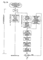
- eine Schemadarstellung eines Steuerungsablaufes zur Durchführung des Sterilisations- bzw. Desinfektionsverfahrens.
Claims (25)
- Dampfsterilisations- bzw. Desinfektionsverfahren zur Behandlung von Sterilgut im Inneren einer Kammer, bei welchem' dadurch gekennzeichnet, daßim Rahmen eines vorbereitenden, der Gasentfernung dienenden Verfahrensschrittes ein zunächst in der Kammer befindliches Gas-Medium aus dieser weitgehend entfernt wird, indem durch Absaugen des Gas-Mediums der Druck im Inneren der Kammer abgesenkt wird, bevor Dampf zur Bildung eines aus dem verbliebenen Gas-Medium und dem Dampf bestehenden Misch-Mediums in die Kammer eingebracht wird, bis ein bestimmter Überdruckpegel erreicht ist und das gebildete Misch-Medium anschließend aus der Kammer ausgebracht wird,im Rahmen eines nachfolgenden Sterilisierschrittes zum Abtöten etwaiger Keime, Dampf in die Kammer eingebracht wird und in der Kammer unter Aufrechterhaltung eines hinsichtlich Druck und/oder Temperatur definierten Dampfzustandes über eine vorbestimmte Zeitperiode verbleibt undim Rahmen eines Trocknungsschrittes zum Trocknen des Sterilgutes der Druck aus der Kammer weitgehend entfemt wird, die Kammer nach Angleich des Druckes in der Kammer an den Umgebungsdruck geöffnet wird, und das behandelte Sterilgut aus der Kammer entnommen wird,im Rahmen des Trocknungsschrittes vor einem Absenken des Druckes auf einen Trocken-Druckpegel unterhalb des Umgebungsdruckes für eine vorbestimmte Trokken-Haltezeit ein nicht-kondensierbares Gas-Medium, insbesondere Luft, in die noch mit Dampf gefüllte Kammer eingebracht und dadurch der Dampf weitgehend, aus der Kammer verdrängt wird.
- Verfahren nach Anspruch 1, dadurch gekennzeichnet, daß im Rahmen des Trocknungsschrittes vor Einbringen des nicht-kondensierbaren Gases der Druck im Inneren der Kammer im wesentlichen auf Umgebungsdruck abgesenkt wird.
- Verfahren nach Anspruch 1 oder 2, dadurch gekennzeichnet, daß der im Rahmen des Trocknungsschrittes verdrängte Dampf oder ein mit diesem gebildetes Misch-Medium im Zustand weitgehender Gleichheit zwischen dem Druck im Inneren der Kammer und dem Umgebungsdruck aus der Kammer ausgebracht wird.
- Verfahren nach einem der Ansprüche 1 bis 3, dadurch gekennzeichnet, daß im Rahmen des Trocknungsschrittes zumindest ein Teil des in der Kammer gebildeten Misch-Mediums unter geringem Überdruck aus der Kammer abgelassen, insbesondere ausgespült wird.
- Verfahren nach Anspruch 3, dadurch gekennzeichnet, daß die Kammer mittels des nicht-kondensierbaren Gases gespült wird, bis der Dampfanteil in der Kammer auf einen vorgeschlagenen Wert, vorzugsweise unterhalb 10 Vol.% abgesunken ist
- Verfahren nach einem der Ansprüche 1 bis 5, dadurch gekennzeichnet, daß das im Rahmen des Trocknungsschrittes eingebrachte Gas-Medium derart in die Kammer engebracht wird, daß dieses den in der Kammer noch befindlichen Dampf zu einem Ablaßabschnitt hin verdrängt.
- Verfahren nach Anspruch 6, dadurch gekennzeichnet, daß das im Rahmen des Trocknungsschrittes der Kammer zugeführte Gas-Medium solange zugeführt wird, bis in der Kammer im wesentlichen Umgebungsdruck oder ein höherer Druckpegel herrscht.
- Verfahren nach einem der Ansprüche 1 bis 7, dadurch gekennzeichnet, daß das Gas-Medium im Rahmen des Trocknungsschrittes in die Kammer unter Bildung einer Verdrängungsströmung eingeführt wird.
- Verfahren nach einem der Ansprüche 1 bis 8, dadurch gekennzeichnet, daß das Gas-Medium im Rahmen des Trocknungsschrittes derart zugeführt wird, daß dieses zunächst den unteren Bereich der Kammer erfüllt.
- Verfahren nach einem der Ansprüche 1 bis 9, dadurch gekennzeichnet, daß das verdrängte Medium im Rahmen des Trocknungsschrittes im oberen Bereich der Kammer aus dieser abgeführt wird.
- Verfahren nach einem der Ansprüche 1 bis 10, dadurch gekennzeichnet, daß im Rahmen des Trocknungsschrittes das Gas-Medium an mehreren Orten gerichtet in die Kammer eingeleitet wird, insbesondere über eine Lochblechanordnung derart gleichmäßig gerichtet, die Kammer ausfüllt, daß der Dampf vor einer durch das Gas-Medium gebildeten Gas-Front zu einem Auslaßbereich hin ausgeschoben wird.
- Verfahren nach einem der Ansprüche 1 bis 11, dadurch gekennzeichnet, daß das in der Kammer befindliche Medium über einen großflächig ausgebildeten Austrittsbereich aus der Kammer abgesaugt wird.
- Verfahren nach einem der Ansprüche 1 bis 12, dadurch gekennzeichnet, daß die Absaugung des in der Kammer befindlichen Mediums mittels einer Vakuumpumpe (P) erfolgt.
- Verfahren nach einem der Ansprüche 1 bis 12, dadurch gekennzeichnet, daß das zur Verdrängung des Dampfes im Rahmen des Trocknungsschrittes eingesetzte Gas-Medium vor Eintritt in die Kammer erwärmt bzw. erhitzt und/oder getrocknet wird.
- Verfahren nach einem der Ansprüche 1 bis 13, dadurch gekennzeichnet, daß der Dampfanteil im Inneren der Kammer erfaßt wird.
- Verfahren nach einem der Ansprüche 1 bis 15, dadurch gekennzeichnet, daß der Überdruckpegel in etwa dem halben im Rahmen des Sterilisierschrittes eingestellten Sterilisierdruckpegel entspricht.
- Verfahren nach einem der Ansprüche 1 bis 16, dadurch gekennzeichnet, daß im Rahmen des vorbereitenden Verfahrensschrittes mehrfach Dampf der Kammer zugeführt wird und nach jedem Dampfzufuhrschritt das gebildete Misch-Medium aus der Kammer abgelassen wird.
- Verfahren nach zumindest einem der Ansprüche 1 bis 17, dadurch gekennzeichnet, daß der im Rahmen des vorbereitenden Verfahrensschrittes eingebrachte Dampf derart in die Kammer eingeleitet wird, daß dieser das in der Kammer zunächst befindliche Gasmedium zu einem Ablaßabschnitt hin verdrängt.
- Verfahren nach zumindest einem der Ansprüche 1 bis 18, dadurch gekennzeichnet, daß während des Ablassens des Misch-Mediums weiterhin Dampf in die Kammer nachgeführt wird.
- Verfahren nach zumindest einem der Ansprüche 1 bis 19, dadurch gekennzeichnet, daß der Dampf Sattdampf ist.
- Vorrichtung zur Durchführung eines Dampfsterilisations- bzw. Desinfektionsverfahrens zur Behandlung von Sterilgut im Inneren einer Kammer, insbesondere nach einem Verfahren gemäß einem der Ansprüche 1 bis 20 mitdadurch gekennzeichnet, daßeiner Kammer (3) zur Aufnahme von zu behandelndem Sterilgut (1),einer ersten Einrichtung (L1) zur Einleitung von Dampf in die Kammer (3), einer zweiten Einrichtung (L2) zur Einleitung eines nicht kondensierbaren Gases, insbesondere Luft in die Kammer (3),einer Ableitungseinrichtung (L3) zur Ableitung eines in der Kammer befindlichen Mediums aus der Kammer (3), einer ersten Ventileinrichtung (A1,A15,A3,A4) zur Steuerung der Zuleitung von Dampf nach Maßgabe einer Steuereinheit (6), einer zweiten Ventileinrichtung (A2,A16,A17,A12) zur Steuerung der Zuleitung des nicht-kondensierbaren Gases nach Maßgabe der Steuereinheit (6),einer dritten Ventileinrichtung (A2,A6,A7) zur Steuerung des Volumenstroms durch die Ableitungseinrichtung (L3), nach Maßgabe der Steuereinheit (6),ein nach dem Sterilisierabschnitt in der Kammer (3) befindliches Dampf-Medium zumindest teilweise über die Ableitungseinrichtung (L3) verdrängbar ist, indem über die zweite Einleitungseinrichtung das nicht kondensierbare Gas-Medium zeitgleich zuleitbar ist, wobei die Steuereinheit (6) die Ventileinrichtungen individuell ansteuert, und daßeine Vakuumpumpe (P) vorgesehen ist, mittels der in der Kammer (3) ein Unterdruck durch Absaugen eines in der Kammer (3) befindlichen Mediums erzeugbar ist.
- Vorrichtung nach Anspruch 21, dadurch gekennzeichnet, daß eine Wärmetauschereinrichtung vorgesehen ist, durch die das der Kammer (3) zugeführte, nicht kondensierbare Gas erwärmbar ist.
- Vorrichtung nach Anspruch 21, dadurch gekennzeichnet, daß die Wärmetauschereinrichtung (5) mit der Ableitungseinrichtung verbunden ist, und daß dadurch das über die Zufuhrleitung (10) zugeführte, nicht kondensierbare Gas vor Eintritt in die Kammer (3) durch den abgeführten Dampf erwärmbar ist.
- Vorrichtung nach einem der Ansprüche 21 bis 23, dadurch gekennzeichnet, daß eine Lochblecheinrichtung (14) vorgesehen ist, durch die das nicht kondensierbare Gas in die Kammer (3) großflächig anleitbar ist.
- Vorrichtung nach einem der Ansprüche 21 bis 24 dadurch gekennzeichnet, daß die Vakuumpumpe (P) als trocken laufende Pumpe, insbesondere Drehkolbenpumpe ausgebildet ist.
Applications Claiming Priority (3)
| Application Number | Priority Date | Filing Date | Title |
|---|---|---|---|
| DE19751692 | 1997-11-21 | ||
| DE19751692A DE19751692A1 (de) | 1997-11-21 | 1997-11-21 | Dampfsterilisations- bzw. Dampfdesinfektionsverfahren und Vorrichtung zur Durchführung des Verfahrens |
| PCT/EP1998/007394 WO1999026667A2 (de) | 1997-11-21 | 1998-11-18 | Dampfsterilisations- bzw. dampfdesinfektionsverfahren und vorrichtung zur durchführung des verfahrens |
Publications (2)
| Publication Number | Publication Date |
|---|---|
| EP1032432A2 EP1032432A2 (de) | 2000-09-06 |
| EP1032432B1 true EP1032432B1 (de) | 2003-01-15 |
Family
ID=7849464
Family Applications (1)
| Application Number | Title | Priority Date | Filing Date |
|---|---|---|---|
| EP98965164A Expired - Lifetime EP1032432B1 (de) | 1997-11-21 | 1998-11-18 | Dampfsterilisations- bzw. dampfdesinfektionsverfahren und vorrichtung zur durchführung des verfahrens |
Country Status (7)
| Country | Link |
|---|---|
| EP (1) | EP1032432B1 (de) |
| AT (1) | ATE231006T1 (de) |
| AU (1) | AU2049399A (de) |
| DE (2) | DE19751692A1 (de) |
| DK (1) | DK1032432T3 (de) |
| ES (1) | ES2190133T3 (de) |
| WO (1) | WO1999026667A2 (de) |
Cited By (1)
| Publication number | Priority date | Publication date | Assignee | Title |
|---|---|---|---|---|
| CN101433728B (zh) * | 2007-11-13 | 2013-05-01 | 意萨股份公司 | 蒸汽灭菌系统 |
Families Citing this family (15)
| Publication number | Priority date | Publication date | Assignee | Title |
|---|---|---|---|---|
| DE10118580C2 (de) * | 2001-04-16 | 2003-03-13 | Fritz Curtius | Verfahren zur Behandlung der Atmosphäre in Autoklaven |
| US7094225B2 (en) | 2001-05-03 | 2006-08-22 | Glaukos Corporation | Medical device and methods of use of glaucoma treatment |
| DE10126634A1 (de) * | 2001-05-31 | 2002-12-12 | Siemens Ag | Dampfsterilisator |
| DE20321304U1 (de) * | 2003-10-17 | 2006-09-14 | Meiko Maschinenbau Gmbh & Co.Kg | Reinigungs- und Desinfektionsautomat |
| EP1527815A1 (de) * | 2003-10-28 | 2005-05-04 | Wiessner GmbH | Verfahren und Vorrichtung zum Abführen unerwünschter Substanzen aus Prozessprodukten und/oder Autoklaven |
| EP2060790A1 (de) * | 2007-11-13 | 2009-05-20 | CISA S.p.A. | Hochvakuumpumpe für Hochtemperatursattdampf. |
| CN101732737B (zh) * | 2010-01-07 | 2012-09-05 | 甘肃奇正藏药有限公司 | 一种中药饮片蒸汽灭菌装置 |
| CN101732738B (zh) * | 2010-01-07 | 2012-09-05 | 西藏奇正藏药股份有限公司 | 一种藏药原生药蒸汽灭菌装置 |
| ITMI20131023A1 (it) * | 2013-06-20 | 2014-12-21 | Absolute Up S R L | Sterilizzatrice a vapore |
| ITPR20130084A1 (it) * | 2013-10-22 | 2015-04-23 | Newmed S R L | Metodo di sterilizzazione di oggetti in autoclave |
| BR102013030702B1 (pt) * | 2013-11-28 | 2019-12-24 | Cisabrasile Ltda | sistema de vácuo para equipamentos de esterilização sem utilização de água ilimitado ao vapor saturado |
| US9671167B1 (en) * | 2015-11-13 | 2017-06-06 | American Sterilizer Company | Process for reducing the temperature of an effluent stream flowing out of a sterilization chamber |
| US20180071415A1 (en) * | 2016-09-09 | 2018-03-15 | Sp Industries, Inc. | Repeated sterile use of a gauge in a steam sterilizable freeze-drying system |
| CN108308509A (zh) * | 2018-04-09 | 2018-07-24 | 太仓鼎膳食品有限公司 | 一种余热利用率高的安全压力蒸汽灭菌锅 |
| CN114588285B (zh) * | 2022-03-22 | 2023-12-01 | 山东新华医疗器械股份有限公司 | 一种灭菌方法 |
Family Cites Families (13)
| Publication number | Priority date | Publication date | Assignee | Title |
|---|---|---|---|---|
| US4203947A (en) * | 1977-11-11 | 1980-05-20 | American Sterilizer Company | Load conditioning control apparatus for steam sterilization |
| US4238447A (en) * | 1978-05-31 | 1980-12-09 | Better Built Machinery Corporation | Steam sterilizing process |
| US4335071A (en) * | 1980-10-06 | 1982-06-15 | American Sterilizer Company | Pressure-vacuum purge cycle |
| DE3119037A1 (de) * | 1981-05-13 | 1982-12-02 | Ganzhorn u. Stirn GmbH + Co, 7170 Schwäbisch Hall | Verfahren und vorrichtung zum sterilisieren |
| SE8206495L (sv) * | 1982-11-15 | 1984-05-16 | Landstingens Inkopscentral | Sett att sterilisera gods i autoklav med omvexlande overtrycksanga och vakuum samt autoklav for genomforande av settet |
| DE3425412A1 (de) * | 1984-07-10 | 1986-01-16 | MMM Münchener Medizin Mechanik GmbH, 8000 München | Verfahren und vorrichtung zur steuerung von sterilisations- oder desinfektionsprozessen |
| DE3505340C2 (de) * | 1985-02-15 | 1994-02-17 | Muenchner Medizin Mechanik | Verfahren zum Wasserdampfsterilisieren von Wäsche od. dgl. |
| US4808377A (en) * | 1985-07-26 | 1989-02-28 | American Sterilizer Company | Self-contained, closed loop steam sterilizer |
| DE4312474C1 (de) * | 1993-04-16 | 1994-11-17 | Stiefenhofer Gmbh C | Dampfsterilisator mit Wärmerückgewinnung |
| EP0731715A1 (de) * | 1993-11-26 | 1996-09-18 | ELECTRICAL CONTROL SYSTEMS PTY. Ltd. | Autoklavierungsverfahren und gerät |
| DE4417512C2 (de) * | 1994-05-19 | 1995-05-04 | Rainer Ringeisen | Verfahren zur Vakuum-Dampf-Sterilisation von Müll |
| DE4445054C3 (de) * | 1994-12-07 | 2002-11-21 | Melagapp Gmbh & Co Kg | Dampfsterilisator |
| GB9626222D0 (en) * | 1996-12-18 | 1997-02-05 | Smiths Industries Plc | Autoclaves and method of operation |
-
1997
- 1997-11-21 DE DE19751692A patent/DE19751692A1/de not_active Withdrawn
-
1998
- 1998-11-18 AU AU20493/99A patent/AU2049399A/en not_active Abandoned
- 1998-11-18 ES ES98965164T patent/ES2190133T3/es not_active Expired - Lifetime
- 1998-11-18 DE DE59806960T patent/DE59806960D1/de not_active Expired - Lifetime
- 1998-11-18 DK DK98965164T patent/DK1032432T3/da active
- 1998-11-18 EP EP98965164A patent/EP1032432B1/de not_active Expired - Lifetime
- 1998-11-18 AT AT98965164T patent/ATE231006T1/de active
- 1998-11-18 WO PCT/EP1998/007394 patent/WO1999026667A2/de not_active Ceased
Cited By (1)
| Publication number | Priority date | Publication date | Assignee | Title |
|---|---|---|---|---|
| CN101433728B (zh) * | 2007-11-13 | 2013-05-01 | 意萨股份公司 | 蒸汽灭菌系统 |
Also Published As
| Publication number | Publication date |
|---|---|
| DK1032432T3 (da) | 2003-04-22 |
| EP1032432A2 (de) | 2000-09-06 |
| WO1999026667A3 (de) | 1999-08-26 |
| AU2049399A (en) | 1999-06-15 |
| DE19751692A1 (de) | 1999-05-27 |
| DE59806960D1 (de) | 2003-02-20 |
| ES2190133T3 (es) | 2003-07-16 |
| ATE231006T1 (de) | 2003-02-15 |
| WO1999026667A2 (de) | 1999-06-03 |
Similar Documents
| Publication | Publication Date | Title |
|---|---|---|
| EP1032432B1 (de) | Dampfsterilisations- bzw. dampfdesinfektionsverfahren und vorrichtung zur durchführung des verfahrens | |
| DE69302570T2 (de) | Vakuum-schleuse zu einem geschlossenen umfang - lösungsmittel - konservierungssystem | |
| EP0386862B1 (de) | Gargerät | |
| DE69407138T2 (de) | Ofen mit Vorrichtung zur Behandlung von überschüssigem Dampf | |
| DE4113174C2 (de) | ||
| EP1222853A2 (de) | Verfahren und Vorrichtung zum Melken | |
| DE102006036475A1 (de) | Verfahren zur Sterilisation von Reinräumen für die Behandlung und/oder das Füllen und Verschließen von Behältern | |
| DE19930546C1 (de) | Dampfsterilisator | |
| DE69423569T2 (de) | Sterilisierungsverfahren und Anlage für einen Dampfautoklav | |
| DE2710968A1 (de) | Verfahren und vorrichtung zur sterilisierung von gegenstaenden in einem autoklaven | |
| EP1257363A2 (de) | Vorrichtung zum filtern und beseitigen von flüssigkeiten | |
| DE3513021A1 (de) | Verfahren und vorrichtung zum waermebehandeln von fliessfaehigen materialien | |
| DE3340050A1 (de) | Verfahren zum sterilisieren von gegenstaenden in einem dampfdrucksterilisator und abwechselndem einsatz von dampfueberdruck und vakuum, sowie dampfdrucksterilisator zur durchfuehrung des verfahrens | |
| DE69200056T2 (de) | Wärmebehandlungsvorrichtung mit reduziertem Druck. | |
| CH682054A5 (de) | ||
| DE4445054A1 (de) | Dampfsterilisator | |
| DE60217891T2 (de) | Verfahren und vorrichtung zur sterilisation von biologischem abfall | |
| DE2313484C3 (de) | Vorrichtung zur Sterilisation, insbesondere von chirurgischen Instrumenten | |
| DE69904629T2 (de) | Entsorgungseinheit für sanitäre abfälle | |
| DE10114946A1 (de) | Verfahren zum Desinfizieren von Abfällen | |
| DE60131151T2 (de) | Methode zur verhinderung von bakterienwachstum in einem kühlsystem für einen kompressor | |
| DE3642175A1 (de) | Verfahren und vorrichtung zum behandeln von lebensmittelware mit rauch | |
| DE202021102871U1 (de) | Vorrichtung zur alkalischen Hydrolyse von organischem Material | |
| DE4235512C2 (de) | Verfahren und Kraftfahrzeug zum Desinfizieren von, insbesondere medizinischem oder dergleichen, Abfall | |
| EP2604292A1 (de) | Reinigungsverfahren für den Nutzraum eines Brutschranks |
Legal Events
| Date | Code | Title | Description |
|---|---|---|---|
| PUAI | Public reference made under article 153(3) epc to a published international application that has entered the european phase |
Free format text: ORIGINAL CODE: 0009012 |
|
| 17P | Request for examination filed |
Effective date: 20000511 |
|
| AK | Designated contracting states |
Kind code of ref document: A2 Designated state(s): AT BE CH DE DK ES FR GB IT LI NL |
|
| 17Q | First examination report despatched |
Effective date: 20010607 |
|
| GRAG | Despatch of communication of intention to grant |
Free format text: ORIGINAL CODE: EPIDOS AGRA |
|
| GRAG | Despatch of communication of intention to grant |
Free format text: ORIGINAL CODE: EPIDOS AGRA |
|
| GRAH | Despatch of communication of intention to grant a patent |
Free format text: ORIGINAL CODE: EPIDOS IGRA |
|
| GRAH | Despatch of communication of intention to grant a patent |
Free format text: ORIGINAL CODE: EPIDOS IGRA |
|
| GRAA | (expected) grant |
Free format text: ORIGINAL CODE: 0009210 |
|
| AK | Designated contracting states |
Kind code of ref document: B1 Designated state(s): AT BE CH DE DK ES FR GB IT LI NL |
|
| REG | Reference to a national code |
Ref country code: CH Ref legal event code: NV Representative=s name: PATENTANWALTSBUERO JEAN HUNZIKER Ref country code: GB Ref legal event code: FG4D Free format text: NOT ENGLISH Ref country code: CH Ref legal event code: EP |
|
| GBT | Gb: translation of ep patent filed (gb section 77(6)(a)/1977) |
Effective date: 20030115 |
|
| REF | Corresponds to: |
Ref document number: 59806960 Country of ref document: DE Date of ref document: 20030220 Kind code of ref document: P |
|
| REG | Reference to a national code |
Ref country code: DK Ref legal event code: T3 |
|
| REG | Reference to a national code |
Ref country code: ES Ref legal event code: FG2A Ref document number: 2190133 Country of ref document: ES Kind code of ref document: T3 |
|
| ET | Fr: translation filed | ||
| PLBE | No opposition filed within time limit |
Free format text: ORIGINAL CODE: 0009261 |
|
| STAA | Information on the status of an ep patent application or granted ep patent |
Free format text: STATUS: NO OPPOSITION FILED WITHIN TIME LIMIT |
|
| 26N | No opposition filed |
Effective date: 20031016 |
|
| PGFP | Annual fee paid to national office [announced via postgrant information from national office to epo] |
Ref country code: DK Payment date: 20061128 Year of fee payment: 9 Ref country code: BE Payment date: 20061128 Year of fee payment: 9 |
|
| PGFP | Annual fee paid to national office [announced via postgrant information from national office to epo] |
Ref country code: NL Payment date: 20061130 Year of fee payment: 9 |
|
| BERE | Be: lapsed |
Owner name: MUNCHENER MEDIZIN MECHANIK G.M.B.H. *MMM Effective date: 20071130 |
|
| REG | Reference to a national code |
Ref country code: DK Ref legal event code: EBP |
|
| NLV4 | Nl: lapsed or anulled due to non-payment of the annual fee |
Effective date: 20080601 |
|
| PG25 | Lapsed in a contracting state [announced via postgrant information from national office to epo] |
Ref country code: BE Free format text: LAPSE BECAUSE OF NON-PAYMENT OF DUE FEES Effective date: 20071130 |
|
| PG25 | Lapsed in a contracting state [announced via postgrant information from national office to epo] |
Ref country code: NL Free format text: LAPSE BECAUSE OF NON-PAYMENT OF DUE FEES Effective date: 20080601 Ref country code: DK Free format text: LAPSE BECAUSE OF NON-PAYMENT OF DUE FEES Effective date: 20071130 |
|
| PGFP | Annual fee paid to national office [announced via postgrant information from national office to epo] |
Ref country code: ES Payment date: 20141112 Year of fee payment: 17 Ref country code: CH Payment date: 20141125 Year of fee payment: 17 Ref country code: GB Payment date: 20141121 Year of fee payment: 17 |
|
| PGFP | Annual fee paid to national office [announced via postgrant information from national office to epo] |
Ref country code: FR Payment date: 20141120 Year of fee payment: 17 Ref country code: AT Payment date: 20141126 Year of fee payment: 17 |
|
| PGFP | Annual fee paid to national office [announced via postgrant information from national office to epo] |
Ref country code: IT Payment date: 20141120 Year of fee payment: 17 |
|
| REG | Reference to a national code |
Ref country code: CH Ref legal event code: PL |
|
| REG | Reference to a national code |
Ref country code: AT Ref legal event code: MM01 Ref document number: 231006 Country of ref document: AT Kind code of ref document: T Effective date: 20151118 |
|
| GBPC | Gb: european patent ceased through non-payment of renewal fee |
Effective date: 20151118 |
|
| PG25 | Lapsed in a contracting state [announced via postgrant information from national office to epo] |
Ref country code: IT Free format text: LAPSE BECAUSE OF NON-PAYMENT OF DUE FEES Effective date: 20151118 Ref country code: CH Free format text: LAPSE BECAUSE OF NON-PAYMENT OF DUE FEES Effective date: 20151130 Ref country code: LI Free format text: LAPSE BECAUSE OF NON-PAYMENT OF DUE FEES Effective date: 20151130 |
|
| REG | Reference to a national code |
Ref country code: FR Ref legal event code: ST Effective date: 20160729 |
|
| PG25 | Lapsed in a contracting state [announced via postgrant information from national office to epo] |
Ref country code: AT Free format text: LAPSE BECAUSE OF NON-PAYMENT OF DUE FEES Effective date: 20151118 |
|
| PG25 | Lapsed in a contracting state [announced via postgrant information from national office to epo] |
Ref country code: GB Free format text: LAPSE BECAUSE OF NON-PAYMENT OF DUE FEES Effective date: 20151118 |
|
| PG25 | Lapsed in a contracting state [announced via postgrant information from national office to epo] |
Ref country code: FR Free format text: LAPSE BECAUSE OF NON-PAYMENT OF DUE FEES Effective date: 20151130 |
|
| REG | Reference to a national code |
Ref country code: ES Ref legal event code: FD2A Effective date: 20161228 |
|
| PGFP | Annual fee paid to national office [announced via postgrant information from national office to epo] |
Ref country code: DE Payment date: 20161124 Year of fee payment: 19 |
|
| PG25 | Lapsed in a contracting state [announced via postgrant information from national office to epo] |
Ref country code: ES Free format text: LAPSE BECAUSE OF NON-PAYMENT OF DUE FEES Effective date: 20151119 |
|
| REG | Reference to a national code |
Ref country code: DE Ref legal event code: R119 Ref document number: 59806960 Country of ref document: DE |
|
| PG25 | Lapsed in a contracting state [announced via postgrant information from national office to epo] |
Ref country code: DE Free format text: LAPSE BECAUSE OF NON-PAYMENT OF DUE FEES Effective date: 20180602 |