EP1032460B1 - Snowboardkörper - Google Patents
Snowboardkörper Download PDFInfo
- Publication number
- EP1032460B1 EP1032460B1 EP98958088A EP98958088A EP1032460B1 EP 1032460 B1 EP1032460 B1 EP 1032460B1 EP 98958088 A EP98958088 A EP 98958088A EP 98958088 A EP98958088 A EP 98958088A EP 1032460 B1 EP1032460 B1 EP 1032460B1
- Authority
- EP
- European Patent Office
- Prior art keywords
- snowboard
- thickness
- cross
- rider
- inertia
- Prior art date
- Legal status (The legal status is an assumption and is not a legal conclusion. Google has not performed a legal analysis and makes no representation as to the accuracy of the status listed.)
- Expired - Lifetime
Links
- 238000005452 bending Methods 0.000 claims description 20
- 238000004519 manufacturing process Methods 0.000 claims description 7
- 230000009977 dual effect Effects 0.000 claims description 3
- 239000011162 core material Substances 0.000 description 55
- 239000000463 material Substances 0.000 description 24
- 239000002023 wood Substances 0.000 description 19
- 239000006260 foam Substances 0.000 description 12
- 238000010276 construction Methods 0.000 description 11
- 238000000034 method Methods 0.000 description 10
- 239000002131 composite material Substances 0.000 description 6
- 239000004744 fabric Substances 0.000 description 6
- 239000011152 fibreglass Substances 0.000 description 5
- 230000027455 binding Effects 0.000 description 4
- 238000009739 binding Methods 0.000 description 4
- 230000008569 process Effects 0.000 description 4
- 229910000831 Steel Inorganic materials 0.000 description 3
- 235000013405 beer Nutrition 0.000 description 3
- 230000008901 benefit Effects 0.000 description 3
- -1 e.g. Substances 0.000 description 3
- 229920006332 epoxy adhesive Polymers 0.000 description 3
- 230000002787 reinforcement Effects 0.000 description 3
- 239000007787 solid Substances 0.000 description 3
- 239000010959 steel Substances 0.000 description 3
- 244000025254 Cannabis sativa Species 0.000 description 2
- 235000012766 Cannabis sativa ssp. sativa var. sativa Nutrition 0.000 description 2
- 235000012765 Cannabis sativa ssp. sativa var. spontanea Nutrition 0.000 description 2
- 235000009120 camo Nutrition 0.000 description 2
- 235000005607 chanvre indien Nutrition 0.000 description 2
- 239000011487 hemp Substances 0.000 description 2
- 238000003475 lamination Methods 0.000 description 2
- 230000003014 reinforcing effect Effects 0.000 description 2
- 230000000284 resting effect Effects 0.000 description 2
- 239000004698 Polyethylene Substances 0.000 description 1
- 208000037063 Thinness Diseases 0.000 description 1
- 230000009286 beneficial effect Effects 0.000 description 1
- 230000015572 biosynthetic process Effects 0.000 description 1
- 230000008859 change Effects 0.000 description 1
- 238000005520 cutting process Methods 0.000 description 1
- 230000007547 defect Effects 0.000 description 1
- 230000007812 deficiency Effects 0.000 description 1
- 230000001419 dependent effect Effects 0.000 description 1
- 230000000694 effects Effects 0.000 description 1
- 238000005516 engineering process Methods 0.000 description 1
- 230000003203 everyday effect Effects 0.000 description 1
- 238000005187 foaming Methods 0.000 description 1
- 230000006872 improvement Effects 0.000 description 1
- 238000007689 inspection Methods 0.000 description 1
- 238000012804 iterative process Methods 0.000 description 1
- 238000010030 laminating Methods 0.000 description 1
- 238000012986 modification Methods 0.000 description 1
- 230000004048 modification Effects 0.000 description 1
- 239000004033 plastic Substances 0.000 description 1
- 229920003023 plastic Polymers 0.000 description 1
- 229920000728 polyester Polymers 0.000 description 1
- 229920000573 polyethylene Polymers 0.000 description 1
- 125000006850 spacer group Chemical group 0.000 description 1
- 230000003068 static effect Effects 0.000 description 1
- 239000004753 textile Substances 0.000 description 1
- 229920000785 ultra high molecular weight polyethylene Polymers 0.000 description 1
- 238000009827 uniform distribution Methods 0.000 description 1
- 230000000007 visual effect Effects 0.000 description 1
Images



Classifications
-
- A—HUMAN NECESSITIES
- A63—SPORTS; GAMES; AMUSEMENTS
- A63C—SKATES; SKIS; ROLLER SKATES; DESIGN OR LAYOUT OF COURTS, RINKS OR THE LIKE
- A63C5/00—Skis or snowboards
- A63C5/03—Mono skis; Snowboards
Definitions
- This invention relates to snowboards, and, more particularly, to a snowboard that may be designed to carve an ideal or "perfect” turn during use.
- a skier or snowboarder In order to initiate a turn (also called “carving” a turn), a skier or snowboarder applies pressure to the ski or snowboard in a manner that rotates the ski or snowboard about its longitudinal axis, tilting the ski or snowboard up onto one of its edges (often called the “riding edge") and deflecting the ski or snowboard away from the skier or snowboarder. Under ideal conditions, the riding edge of the ski or snowboard will create a single slender cut into the snow as the skier or snowboarder carves the turn. This type of turn is desirable because it minimizes the friction or drag on the ski or snowboard as it moves through the turn. In addition, this type of turn is the easiest to control.
- skis were initially manufactured by ski manufacturers, and most of the initial designers of snowboards were therefore ski designers who understandably borrowed heavily from the accepted wisdom of the ski industry.
- both skis and snowboards use essentially the same materials, e.g., fiberglass ultra high molecular weight polyethylenes, either singly or in laminated combinations with wood cores, steel edges, and plastic tops and sidewalls.
- ski construction e.g., sidewall, sandwich or capped construction, and techniques of manufacture, e.g., presses, composites and laminating, were transferred virtually unchanged to snowboards.
- the longitudinal curvature of a conventional snowboard comprises a curve of varying radii, assuming a U-shape which typically comprises an essentially flat, inflexible portion in the middle of the snowboard, between the foot mounting zones, and upwardly curved ends.
- Carpenter et al. show ( Figure 1) a snowboard having thinner fore and aft sections separated by a thicker central platform having an essentially constant thickness. While being more flexible than Remondet's snowboard, the central platform is still the thickest part of the snowboard, and consequently is resistant to bending.
- Nyman shows (Figure 2) a snowboard having a single camber and an essentially constant thickness from nose to tail (it is not clear whether the constant thickness is an intended characteristic of Nyman's snowboard, or whether it is merely the draftsman's contribution, for the thickness of the snowboard is not mentioned in his specification). While Nyman's snowboard may be a slight improvement over Remondet and Carpenter et al., a rider still cannot apply any combination of pressures which will bend the central portion of Nyman's snowboard into a circular arc.
- Deville et al. disclose a snowboard with a core having a constant thickness in which the torsional and longitudinal stiffness characteristics of the snowboard can be more precisely selected by adding reinforcing members to the surface of the snowboard in various patterns.
- Deville et al. mention incorporating the reinforcements within the "base structure" of the snowboard but do not show nor explain how this would be accomplished.
- the Deville et al. teach providing less reinforcement in the central portion of the snowboard, there is no mention or suggestion of any desire to control the flexibility such that the snowboard will bow into circular arc when in use.
- the widths and thicknesses of the reinforcing members in all of the figures shown the Deville et al. patent are taken literally, the reinforcements will act to prevent such a result.
- Another object of the present invention is to provide a snowboard whose longitudinal flexibility is designed so that the resultant structure forms a curvature of constant radius, i.e., a circle, during use.
- the present invention achieves the foregoing objects by providing a snowboard whose flexibility along its length is designed so that during use, while executing a turn, the snowboard will bow into an arc having a substantially constant radius of curvature, i.e., a circle.
- the snowboard's flexibility which among other things is a function of the dimensions of the board at any given cross-section, can be controlled to yield bending into a particular radius of curvature (i.e., a circle) if one first determines the desired area moments of inertia of the snowboard at numerous transverse cross-sections.
- the desired area moments of inertia for a given rider and a given snowboard material can be iteratively calculated (preferably with the aid of a computer), the dimensions of the snowboard, and thus bending of the snowboard, at any such cross-section, and thus the ability of the snowboard to bow into an arc having a substantially constant radius of curvature, can be designed, all in accordance with the present invention.
- a snowboard in designing a snowboard that bends into a circular arc, one first selects the type of material(s) to be used for the snowboard, and then determines the weight and skill of the rider for whom the snowboard is being designed (thus lending the present invention to being custom designed). Using these parameters, the bending moments at numerous transverse cross sections along the length of the board can be calculated, as well as the desired maximum curvature of the snowboard when in use. The next step is to select the desired area moments of inertia for such numerous transverse cross-sections. The desired area moments of inertia are functions of the previously calculated bending moments, the desired maximum curvature, and the moduli of elasticity of the materials being used. Finally, the cross-sectional dimensions at each transverse cross-section are selected so that the actual area moment of inertia at each such cross section is equal to the desired area moment of inertia.
- I considered a snowboard as a beam, and a snowboard with a rider thereon as a beam under a load.
- the curvature C of a beam is directly proportional to the load bending the beam (or bending moment M).
- the bending moment M is determined by the length of the snowboard, the placement of the feet on the snowboard, and the weight of the rider. As a preliminary to designing the structure of a particular snowboard, these variables may be considered as constants.
- the curvature is also inversely proportional to the modulus of elasticity of the materials comprising the snowboard and to the area moment of inertia of the cross-sectional area transverse to any point along the longitudinal axis of the snowboard.
- the modulus of elasticity is either uniform throughout the snowboard, or at least is known as a function of the length of the snowboard, so for design purposes, it too may be considered a constant. This leaves the area moment of inertia as the operative variable in controlling the curvature of the snowboard at any point along its length.
- the curvature of a snowboard built in accordance with the present invention is less, i.e., flatter, for large values of the area moment of inertia l and greater, i.e. more curved, for small values of l . That is, for large values of l , the snowboard will not deflect as much under a given load than it will for small values of l .
- the flexibility of segments of the snowboard of the present invention are determined by placing each segment under a known, fixed load. Segments that bend less are less flexible, and segments that bend more are more flexible. Consequently, the relative flexibilities of the various segments are amenable to direct, visual testing.
- Equation (2) has been applied to common shapes, e.g., rectangles, triangle, circles, semi-circles, etc., with known results.
- Rectangle: I bh 3 12
- Triangle: I bh 3 36
- Circle: I ⁇ r 4 4
- Semi-circle: I ⁇ r 4 8
- the area moment of inertia of complex shapes can be determined by subdividing the complex shapes into parts having simpler shapes and by summing the area moments of inertia of the parts. See Beer, supra , pp. 443-447.
- plank i.e., a snowboard of any particular length having a rectangular cross-section of 25.4 mm by 203.2 mm (1 inch by 8 inches), and thereby a cross-sectional area of 5161 mm 2 (eight square inches), placed across a chasm side-by-side with a two-by-four of similar length and same cross-sectional area.
- plank will bend much more (have a higher curvature) than will the two-by-four under the same load, say a person crossing the chasm on them. This can also be seen by referring to equation (3), supra.
- the plank Since its height is less, the plank has a smaller area moment of inertia than does the two-by-four, even though they both have the same cross-sectional area. Since the area moment of inertia is smaller, the plank is more flexible. Turn the two-by-four on edge with the four inches extending vertically and the area moment of inertia of the same piece of wood increases, thereby increasing the rigidity of the snowboard. This is true because the area moment of inertia for rectangles increases linearly with width and cubically with height; thus, the height of the area is the dominating factor.
- equation (1) states that the radius of curvature pof a beam is directly proportional to both the modulus of elasticity E of the material from which the beam is made and the area moment of inertia I of the beam and inversely proportional to the bending moment M of the beam (the resultant of all the forces imposed upon the beam). From this, it can be seen that many of the variables are either constant or can be considered as effectively constant.
- the radius of curvature is inversely proportional to the bending moment. That is, the amount of bowing will depend on the magnitude of the load applied thereto, increasing with increased load. Thus, regardless of the absolute value of the load, the snowboard will bow into a curve of substantially constant radius, when taken in combination with an appropriate set of area moments of inertia.
- One possible method of calculating the appropriate area moment of inertia l at any longitudinal point on the snowboard begins with determining the weight and snowboarding style of the rider that the snowboard is being designed for.
- the rider's style will determine a maximum desired curvature C m of the snowboard.
- a snowboard designed for a more aggressive rider will have a larger maximum curvature C m , and vice versa.
- the horizontal planar dimensions of the snowboard i.e., length, width and side cut depth, are chosen. Generally, a larger maximum curvature C m results in a shallower side cut.
- the position of the rider's feet (also called “mounting zones") on the snowboard are determined. Typically, the mounting zones are positioned to balance the rider's weight on the snowboard during use.
- the bending moment M at the selected point on the snowboard can be calculated given the weight of the rider. It is assumed that the downward force applied by the rider on the snowboard is balanced between the rider's feet and that the snow imposes a uniform upward force on the snowboard equal in magnitude and opposite in direction to the total downward force applied by the rider.
- the core material of the snowboard which has a fixed modulus of elasticity E, is selected. As will be explained below, laminated wood is the most common material. Then, equation (1) is used to determine the desired area moment of inertia I d for the selected point on the snowboard.
- the construction of the snowboard is selected. This includes determining the location, materials and dimensions of the components of the snowboard, e.g., the core, top surface, sidewalls, edges and base (which are discussed in more detail below). However, the thickness of the core is left as a variable and is assumed constant across each transverse cross-section.
- the thickness of the core could be varied along each transverse cross-section (as shown in FIGS. 11-16, discussed below).
- the thickness of the core is assumed to be constant across each transverse cross-section and chosen as the design variable because it results in the simplest actual composite area moment of inertia I a expression (as discussed below) and is the least costly to manufacture.
- the actual area moment of inertia I a In order to achieve the desired curvature C of the snowboard, the actual area moment of inertia I a must be equal to the desired area moment of inertia I d .
- the expression for the actual area moment of inertia I a is typically a 4 th order polynomial and is not easily solvable.
- a value for the appropriate core thickness is "guessed”. Then, the composite area moment of inertia I a is compared to the desired area moment of inertia I d . If the composite area moment of inertia I a is larger than the desired area moment of inertia I d the process is repeated using a smaller value for the core thickness.
- the above-described method is repeated for along the entire length of the snowboard, by selecting a set of longitudinal points at small increments, for example, 5 millimeters apart.
- a snowboard 10 has a nose 12, a tail 14, and a body indicated generally by reference numeral 16.
- Body 16 includes a bottom surface 18, a top surface 20, a front half 22 including a front mounting zone 24, and a rear half 26 including a rear mounting zone 28.
- the front half 22 and rear half 26, and thereby said front and rear mounting zones 24 and 28, are separated by a center section 30.
- the separate regions, areas, zones, sections, portions, and segments of the snowboard of the invention are discussed herein as if they are separate entities. This is for clarity of discussion only. In fact, the inventive snowboard is an integral structure from nose to tail.
- normal loading refers to the load exerted on snowboard 10 bv a rider while snowboard 10 is in use.
- the load is transmitted from the rider to snowboard 10 through the rider's boots, each of which are secured within a conventional snowboard binding.
- Each of the bindings is preferably affixed to top surface 20 of snowboard 10 within front and rear mounting zones 24 and 28, respectively.
- the magnitude of the load exerted on snowboard 10 by the rider will be equal to the weight of the rider, plus any additional forces exerted by the rider on snowboard 10 during use, such as when the rider is executing a turn or landing after executing a jump.
- Normal loading does not include circumstances under which the magnitude of the load exerted on the snowboard is substantially less than the weight of the rider, such as when the rider is in mid-air while executing a jump.
- FIG. 1 depicts a snowboard resting on the surface of the snow without being loaded by the weight of a rider. Under these conditions, bottom surface 18 between nose 12 and tail 14 is flat and coincides with a segment of a circle 5 of infinite radius (FIGS. 1, 6, and 8).
- the vertical thickness of body 16 from bottom surface 18 to top surface 20 changes as a function of the distance along the length of snowboard 10 from nose 12 to tail 14.
- the cross-sectional area as viewed transversely of the snowboard, has a constant thickness, as shown in FIG. 10. That is, the shape of any cross-section taken perpendicular to the longitudinal axis will be essentially a rectangle. The corners may be rounded for aesthetic or functional reasons, as suggested in FIGS. 2-4 and 11-12, but other than these slight modifications, the thickness is essentially uniform across snowboard 10. As can be seen in FIG.
- the thickness of snowboard 10 is relatively thin throughout the upturned curvature of nose 12, thicker in the front mounting zone 24, thinner in center section 30 between front mounting zone 24 and rear mounting zone 28, thicker again in rear mounting zone 28, and thinner again through tail 14.
- Mounting zones 24 and 28 are those areas which support the rider's boots, which as stated above can be variably placed both fore and aft and side to side, as is well known in the art.
- the nose and tail sections extend outboard from the closest mounting zone, and the center section extends between the mounting zones.
- the exact locations of the boundaries may change from snowboard to snowboard, but they are characterized by the relative thicknesses and thinnesses as defined above. It should be understood that the drawings do not show exact proportions for thicknesses, but rather are exaggerated for clarity.
- center section 30 is relatively thin instead of being the thickest part of the snowboard.
- the mounting zones are thick, as is customary, in order to provide structural strength for supporting the rider and to not be overwhelmed by the highly localized forces of the rider's two feet.
- Making center section 30 thinner permits snowboard 10 to bend more readily under normal loading, thereby making snowboard 10 easier to control.
- center section 30 is thin enough that, when the snowboarder shifts his/her weight in a normal manner so as to direct a turn, snowboard 10 will respond by assuming a circular arc of a radius commensurate with the weight shifts. Under those conditions, snowboard 10 will make the turn expected. That is, snowboard 10 will carve a turn in the snow in which rear half 26 substantially follows in the track of front half 22.
- center section 30 It is not merely the increased flexibility of center section 30 which is the hallmark of the present invention, however, for other snowboards, particularly Deville et al., supra , share that characteristic.
- the set of flexibilities of snowboard 10 as measured incrementally along its longitudinal axis must also be selected such that under a normal load, body 16 will bow into a segment of a circle, i.e., an arc of constant radius, as seen at 7 in FIGS. 5, 7, and 9. In the preferred embodiment, this is accomplished by gradually varying the Area Moments of Inertia of body 16, specifically of its core, as explained above.
- the thickness of center section 30 ranged between about 69% and 79% of the thickness of the mounting zones 24, 28.
- a thickness of the center section 30 that is 95% or less than that of mounting zones 24, 28 will meet the objectives of the present invention.
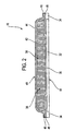
- FIGS. 2-4 show alternative embodiments of cross-sections of snowboard 10 of the present invention, using different materials. Each cross-section is taken along line A-A of FIG. 1, however, the cross-sections shown would be representative of a transverse cross-section taken at any point along a snowboard.
- FIGS. 2-4 are conventional from the standpoint that they all exist in the prior art and are customarily used in the construction of conventional snowboards.
- the selection of the particular cross-sectional dimensions of a snowboard along its length to enable the rider to carve an ideal turn, i.e., to enable the snowboard to bow into a circular arc when the rider executes a turn, constitutes part of the present invention.
- Body 16 includes base 32, the major portion of snowboard 10 which comes in contact with the snow.
- Base 32 is preferably made of an ultra high molecular weight (UHMW) polyethylene, either extruded or sintered, chosen for its durability and the ease with which it glides over the surface of the snow.
- Flanking base 32 and bonded thereto are a pair of edges 34, preferably made of a high grade steel. Edges 34 cut into the snow when snowboard 10 is carving its turns.
- Bottom surface 18 comprises the flush bottom surfaces of base 32 and edges 34.
- a lower structural layer 36 extending from side to side of snowboard 10, is preferably bonded in an epoxy adhesive to base 32 and edges 34.
- the predominant material for structural layer 36 is fiberglass cloth, although there is some use of hemp cloth, other textile materials, and even wood veneer. Fiberglass cloth is preferred and is laid up in either a triaxial, biaxial, or uniaxial direction, depending on the design required.
- Structural layer 36 is also preferably bonded in an epoxy adhesive to a core 38.
- Cores can be made of just about any material. Typically, mainly to ensure economy in manufacture, core 38 is constructed of wood (FIG. 2), foam (FIG. 3), or a combination of wood and foam (FIG. 4). Wood is preferred, but foam, wood and foam, and laminates of fiberglass cloth (not shown) are within the purview of the invention. The details of core 38 will be discussed shortly.
- a cap 40 comprising an upper structural layer 42 and a top sheet 44 is also preferably bonded in an epoxy adhesive to core 38.
- upper structural layer 42 is usually made of fiberglass cloth, although hemp cloth, other cloths, and wood veneer are also known.
- Top sheet 44 is typically a polyester sheet which functions as a canvas on which the snowboard's graphics are displayed.
- Cap 40 is smoothly adhered to core 38 with outwardly extending extremities 46 of upper layer 42 being bonded to edges 48 of lower layer 36 to form a cover which seals core 38 and provides aesthetic protection for body 16.
- cover or “core cover” as used herein and in the claims refers to all structural elements which surround core 38, including cap 40, upper structural layer 42, lower structural layer 36, base 32, and edges 34.
- steel edges 34 have a high rigidity which resists bending of body 16, but their cross-sectional dimensions along the snowboard are substantially constant. That is, they are not varied as a function of the length of the snowboard with a view as to varying the area moment of inertia thereof. Their contribution, therefore, to the flexibility of body 16 is constant, is known, and as such can be accounted for when computing each cross-section's area moment of Inertia. The same can be said for the contributions of base 32, upper and lower layers 42 and 36, and top sheet 44.
- a core Prior to the present invention, the main purpose of a core was to act as a spacer between the upper and lower structural layers to provide shape and solidity to the snowboard body.
- the instant invention expands the functionality of the core by utilizing its cross-sectional shape as the variable of choice in controlling the specific area moment of inertia at any given point along the length of the snowboard.
- it is the core which is modified to control the area moments of inertia.
- the area moment of inertia of core 38 is dependent only on the shape of its cross-section and is independent of the materials comprising same.
- the modulus of elasticity of core 38 is a factor in the radius of curvature of snowboard 10, as is seen from equation (1) above, but it does not enter into the calculations of the area moment of inertia of core 38.
- the materials for core 38 are chosen primarily from cost and availability considerations.
- Wood is the preferred material.
- core 38 is shown as composed of wood.
- thin strips of wood are laminated together to form core 38.
- the strips are typically laminated in a vertically orientation, as shown in FIG. 2, however, horizontal lamination is also employed.
- Lamination is preferred to using single, solid piece of wood for two reasons. First, using a single piece of wood would require a much larger, and therefore more expensive piece of wood. More importantly, obtaining a piece of solid wood that does not contains defects, such as knots, would be extraordinarily expensive.
- core 38 is made of foam 52.
- Core 38 can be manufactured as a solid, prefabricated foam block, or it can be the result of injecting a foaming material into the pocket formed by top layer 42 and lower layer 36.
- Foam is typically less expensive and more durable than wood, but usually is slightly heavier and more damp.
- FIG. 4 shows a combination of wooden strips 50 encased within a sheath of foam 52 to form core 38.
- the cross-sectional shape of core 38 e.g., its thickness, can be controlled by varying either the height of wooden strips 50 or the thickness of foam 52, or both.
- the materials forming core 38 prefferably be uniformly distributed across the transverse cross-sections of core 38, so that there are no sudden, large changes in moduli of elasticity that have to be taken into account when calculating the appropriate set of area moments of inertia for the snowboard.
- only one variable, namely, the relative vertical thicknesses of core 38 needs to be varied to realize the desideratum of the snowboard bowing into an arc of constant radius.
- snowboards having cores with non-uniformly distributed flexibilities are within the scope of the present invention, however, having a core with a uniform consistency, and thereby a uniform flexibility, simplifies the manufacture of the snowboard, which reduces the costs thereof.
- FIGS. 2 and 3 a single material is used, i.e., wood and foam, respectively, for core 38, so a uniform distribution of materials, and thereby a uniformly distributed flexibility, is to be expected.
- FIG. 4 includes two disparate materials, wood and foam, in the formation of core 38.
- the core nevertheless exhibits a uniform flexibility, since both the wooden center and the foam sheath are uniformly distributed and symmetrically oriented relative to the geometry of the cross-sectional area.
- FIG. 5 shows snowboard 10 under the load imposed thereon by a rider.
- the weight of the rider is applied to snowboard 10 in two separated locations, indicated by arrows 54 and 56, in mounting zones 24 and 28, respectively.
- FIG. 5 shows the curvature snowboard 10 under a static load. When carving a turn, snowboard 10 will ride on one edge of body 16.
- the magnitude of the load applied to snowboard 10 by the rider during normal loading will vary, as described above.
- the load exerted by the rider on snowboard 10 will be greater when the rider is executing a sharp turn than when the rider is moving in straight line.
- the snowboard 10 will flex longitudinally into one of a number of arcs, each having a constant radius curvature.
- the magnitude of the radius of curvature of snowboard 10 will vary in direct proportion to the magnitude of the load exerted by the rider.
- rear half 26 will follow in the track of front half 22, and the rider will have carved an ideal turn. Riders will find snowboard 10 much easier to control, especially in sharp turns, than the snowboards of the prior art.
- bottom surface 18 is flat in repose, i.e., it has no camber. As will become apparent, although this embodiment permits the thickness criteria to be visualized most clearly, bottom surface 18 may assume other shapes and still remain within the teachings of the present invention.
- FIG. 6 shows a second preferred embodiment of the present invention.
- FIG. 6 depicts a side view of snowboard 10 having a nose 12, a tail 14, and a body 16.
- Body 16 includes a bottom surface 18, a top surface 20, a front half 22 including a front mounting zone 24, and a rear half 26 including a rear mounting zone 28, separated by a center section 30.
- Snowboard 10 in FIG. 6 is depicted as if resting on the surface of the snow without a rider mounted thereon.
- Bottom surface 18 is unstressed and rests on snow on three riding areas 58, 60, and 62.
- snowboard 10 is thinnest in the areas of nose 12 and tail 14, thinner in center section 30, and thickest under the rider's feet in front mounting zone 24 and rear mounting zone 28.
- FIG. 6 shows snowboard 10 as including dual cambers indicated generally by reference numerals 64 and 68.
- a dual-cambered snowboard is the subject of my prior U.S. utility patent application Serial No. 08/918,906, filed August 27, 1997, now U.S. Pat. No. 5,823,562, assigned to the same assignee as the present invention, and specifically incorporated herein by reference. Dual cambers afford additional ease of control of snowboard 10, as discussed in my aforementioned patent.
- FIG. 7 shows snowboard 10 of FIG. 6 loaded by a rider.
- the materials and area moments of inertia are selected to facilitate the bowing of snowboard 10 into a reasonably close approximation of a circular segment of constant radius.
- the flexibility of body 16 must take into account the presence of the two cambers. As in FIG. 5, when snowboard 10 is under a normal loading, body 16 is longitudinally curved, and when turning, the edge which contacts the snow follows an arc of a circle.
- the third embodiment shown in FIGS. 8 and 9 has a single camber 70.
- the application of the inventive principles disclosed herein to a single camber snowboard is also beneficial.
- the variation in thicknesses along the length of snowboard 10 are thinner in nose 12, center section 30, and tail 14 while being thicker in the mounting zones 24 and 28.
- snowboard 10 rests on riding areas 72 and 74.
- riding areas 72 and 74 are flattened and the direction of the camber is reversed, such that, as in the previous embodiments, bottom surface 18 is in contact with the snow coincident with an arc of a circle 7 of constant radius ⁇ .
- this is due to proper selections of the area moments of inertia along body 16, and again results in a thinner center section 30 between mounting zones 24 and 28.
- FIGS.10-16 show preferred and alternative cross-sectional shapes of transverse areas of core 38 of snowboard 10.
- the active parameter in controlling the area moments of inertia is the cross-sectional shape of core 38
- the shapes thereof are shown in FIGS. 10-16. All have essentially equivalent area moments of inertia.
- the shapes shown are merely illustrative of the possibilities and are not exhaustive of the shapes contemplated as falling within the scope of the present invention.
- FIGS. 10-12 show essentially rectangular cores having a flat top surface 76, a flat bottom surface 78, and mirror-image sides 80-84, respectively.
- Sides 80 in FIG. 10 are at right angles to top and bottom surfaces 76 and 78, which are parallel to each other; this core is the simplest to manufacture.
- Sides 82 in FIG. 11 comprises sloping portions 86 merging into vertical portions 88.
- Sides 84 in FIG. 12 are more stylized, combining an arcuate portion 90 sloping from top surface 76 to a vertical edge 92. The latter two are shaped more for aesthetic reasons than functional ones, although the smoother edges aid in protecting cap 40 (FIGS. 2-4) from stress-related tears.
- FIGS. 13-16 are cross-sections taken between mounting zone 24 and nose 12, in central section 30, and between mounting zone 28 and tail 14.
- the cross-sectional shapes shown merge smoothly into the cross-sections of FIG. 10 (for FIGS. 13-14) and FIG. 12 (for FIGS. 15-16) in the areas of mounting zones 24 and 28.
- Mounting zones 24 and 28 should have reasonably flat, top surfaces 76 in order to provide adequate support for the bindings and boots of the rider.
- the sloping top surfaces 94 and 96 of FIG. 13 and the arcuate surface 98 of FIG. 14 can extend the length of the snowboard, but those configurations require the bindings be shaped to conform thereto while maintaining the boots' bottoms parallel to bottom surfaces 78.
- FIGS. 15 and 16 illustrate cross-sectional shapes which are designed to increase torsional flexibility of snowboard 10 while maintaining the correct longitudinal flexibility of the snowboard.
- Ridges 100 and 102 of FIG. 15 and ridges 104 and 106 of FIG. 16 extend along the full length of the sides of body 10.
- Ridge 108 (FIG. 16) which runs the full length of the midsection of body 16, adds strength longitudinally to the central axis thereof.
- any of the preceding embodiments may have side cuts in order to be able to include all of the advantages derivable therefrom.
- Such side cuts have not been shown in the drawings, since they are not a part of the present inventive concepts.
Landscapes
- Footwear And Its Accessory, Manufacturing Method And Apparatuses (AREA)
- Buildings Adapted To Withstand Abnormal External Influences (AREA)
- Laminated Bodies (AREA)
- Suspension Of Electric Lines Or Cables (AREA)
- Road Paving Structures (AREA)
- Automatic Cycles, And Cycles In General (AREA)
Claims (8)
- Snowboard, das eine Nase (12), einen Schwanz (14) und einen die Nase (12) mit dem Schwanz (14) verbindenden Körper (16) umfasst, wobei der Körper (16) eine Deckoberfläche (20), eine Bodenoberfläche (18), eine vordere Montagezone (24) und eine hintere Montagezone (28) aufweist, wobei die Montagezonen auf der Deckoberfläche (20) angeordnet und durch einen Mittelabschnitt (30) des Körpers (16) getrennt sind, wobei jede der Montagezonen (24, 28) dazu ausgelegt ist, um einen der Füße eines Fahrers des Snowboards aufzunehmen, wobei die Füße eine erste Abwärtskraft (54), die auf die vordere Montagezone (24) wirkt, und eine zweite Abwärtskraft (56), die auf die hintere Montagezone (28) wirkt, ausüben,
wobei der Körper (16) ferner eine Mehrzahl von Querschnittsabschnitten enthält,
dadurch gekennzeichnet, dass der Körper (16) eine Dicke zwischen der Deckoberfläche (20) und der Bodenoberfläche (18) enthält, wobei die Dicke derart ist, dass der Mittelabschnitt (30) dünner ist als die Dicke der vorderen und der hinteren Montagezonen (24, 28), worin der Wert des folgenden Ausdrucks im Wesentlichen konstant ist, wenn er auf jeden der Mehrzahl von Querschnittsabschnitten jeweils angewendet wird, wenn die ersten und zweiten Abwärtskräfte (54, 56) und eine gleichmäßige Aufwärtskraft, die entlang der Bodenoberfläche (18) wirkt, auf das Snowboard ausgeübt werden:derart, dass der Körper (16) im Gebrauch sich in einen Bogen mit konstantem Krümmungsradius biegt.E der Elastizitätsmodul des Körpers für den jeweiligen Querschnittsabschnitt ist,I das Flächenträgheitsmoment für den jeweiligen Querschnittsabschnitt ist; undM das Biegemoment ist, das auf den jeweiligen Querschnittsabschnitt wirkt, wenn die ersten und zweiten Abwärtskräfte und die gleichmäßige Aufwärtskraft auf das Snowboard wirken, - Snowboard nach Anspruch 1, worin die Dicke der vorderen und hinteren Montagezonen (24, 28) dicker ist als die Dicke der Nase (12) und des Schwanzes (14).
- Snowboard nach Anspruch 2, worin der Körper (16) flach ist, wenn das Snowboard unter keiner vom Fahrer ausgeübten Last steht.
- Snowboard nach Anspruch 2, worin der Körper (16) eine einzige Kammer enthält.
- Snowboard nach Anspruch 2, worin der Körper (16) eine Doppelkammer enthält.
- Snowboard nach Anspruch 2, worin die Dicke des Mittelabschnitts (30) etwa 95% oder weniger als die Dicke der Montagezonen (24, 28) beträgt.
- Snowboard nach Anspruch 2, worin die Dicke des Mittelabschnitts (30) zwischen etwa 69% und 79% der Dicke der Montagezonen (24, 28) beträgt.
- Verfahren der Herstellung eines Snowboards des Typs, der eine Nase (12), einen Schwanz (14) und einen die Nase (12) mit dem Schwanz (14) verbindenden Körper (16) enthält, wobei der Körper (16) des Typs eine Deckoberfläche (20) und eine Bodenoberfläche (18) enthält, die dazwischen eine Dicke definieren, eine vordere Montagezone (24) und eine hintere Montagezone (28), wobei die Montagezonen auf der Deckoberfläche (20) angeordnet und durch einen Mittelabschnitt (30) des Körpers (16) getrennt sind, wobei jede der Montagezonen (24, 28) dazu ausgelegt ist, einen der Füße eines Fahrers des Snowboards aufzunehmen,
gekennzeichnet durch die Schritte:Formen des Körpers, wobei die Dicke des Mittelabschnitts (30) dünner ist als die Dicke der vorderen und der hinteren Montagezonen (24, 28), worin der Körper eine Mehrzahl von Querschnittsabschnitten enthält, derart, dass der Wert des folgenden Ausdrucks im Wesentlichen konstant ist, wenn er auf jeden der Mehrzahl von Querschnittsabschnitten jeweils angewendet wird, wenn erste und zweite Abwärtskräfte (54, 56) und eine gleichmäßige Aufwärtskraft, die entlang der Bodenoberfläche (18) wirkt, auf das Snowboard ausgeübt werden:derart, dass der Körper (16) im Gebrauch sich in einen Bogen mit konstantem Krümmungsradius biegt.E der Elastizitätsmodul des Körpers für den jeweiligen Querschnittsabschnitt ist,I das Flächenträgheitsmoment für den jeweiligen Querschnittsabschnitt ist; undM das Biegemoment ist, das auf den jeweiligen Querschnittsabschnitt wirkt, wenn die ersten und zweiten Abwärtskräfte und die gleichmäßige Aufwärtskraft auf das Snowboard wirken,
Applications Claiming Priority (3)
| Application Number | Priority Date | Filing Date | Title |
|---|---|---|---|
| US08/974,287 US6394483B2 (en) | 1997-11-19 | 1997-11-19 | Snowboard body |
| US974287 | 1997-11-19 | ||
| PCT/US1998/024728 WO1999025433A1 (en) | 1997-11-19 | 1998-11-19 | Snowboard body |
Publications (2)
| Publication Number | Publication Date |
|---|---|
| EP1032460A1 EP1032460A1 (de) | 2000-09-06 |
| EP1032460B1 true EP1032460B1 (de) | 2004-01-02 |
Family
ID=25521853
Family Applications (1)
| Application Number | Title | Priority Date | Filing Date |
|---|---|---|---|
| EP98958088A Expired - Lifetime EP1032460B1 (de) | 1997-11-19 | 1998-11-19 | Snowboardkörper |
Country Status (9)
| Country | Link |
|---|---|
| US (1) | US6394483B2 (de) |
| EP (1) | EP1032460B1 (de) |
| JP (1) | JP2001523497A (de) |
| AT (1) | ATE257022T1 (de) |
| AU (1) | AU767678B2 (de) |
| CA (1) | CA2311242A1 (de) |
| DE (1) | DE69820902T2 (de) |
| NZ (1) | NZ505251A (de) |
| WO (1) | WO1999025433A1 (de) |
Cited By (1)
| Publication number | Priority date | Publication date | Assignee | Title |
|---|---|---|---|---|
| AT507737B1 (de) * | 2008-12-23 | 2012-06-15 | Elan Sportartikelerzeugungs Und Handelsges M B H | Snowboard |
Families Citing this family (26)
| Publication number | Priority date | Publication date | Assignee | Title |
|---|---|---|---|---|
| US6234513B1 (en) | 1997-01-31 | 2001-05-22 | James S. Busby, Jr. | Snowboard drive system |
| FR2816219A1 (fr) * | 2000-11-06 | 2002-05-10 | Chronic | Plateau pour planche de glisse pouvant comporter des roulettes ou une surface de glissement |
| DE60119961T2 (de) | 2000-11-17 | 2006-12-21 | Scott Sports S.A. | Ski und snowboard mit veränderlicher radialer geometrie |
| US20020089149A1 (en) | 2001-01-05 | 2002-07-11 | Scott Barbieri | Gliding board with varying bending properties |
| SI22083B (sl) * | 2005-07-18 | 2009-12-31 | Elan, D.O.O. | Smučka ali snežna deska z izboljšano torzijsko togostjo |
| FR2896424B1 (fr) * | 2006-01-25 | 2008-04-18 | Salomon Sa | Planche de glisse ou de roulage |
| US7690674B2 (en) * | 2006-08-10 | 2010-04-06 | Armada Skis, Inc. | Snow riding implement |
| US7823892B2 (en) * | 2007-05-04 | 2010-11-02 | Quiksilver, Inc. | Snowboard |
| FR2916361B1 (fr) * | 2007-05-25 | 2012-08-31 | Rossignol Sa | Planche de ski alpin |
| FR2926735B1 (fr) * | 2008-01-25 | 2010-03-26 | Salomon Sa | Ski alpin avec moyens de reglage |
| US7832742B1 (en) | 2008-02-15 | 2010-11-16 | Duggan John C | Ergonomically advanced rotating boot and foot mounting system for sportboards |
| US7798514B2 (en) * | 2008-04-10 | 2010-09-21 | Never Summer Industries, Inc. | Cambered snowboard |
| US9044664B1 (en) * | 2008-04-10 | 2015-06-02 | Never Summer Industries, Inc. | Cambered snowboard |
| FR2939323B1 (fr) * | 2008-12-08 | 2011-03-25 | Salomon Sas | Ski alpin avec flexion controlee |
| PL387143A1 (pl) | 2009-01-28 | 2010-08-02 | Dariusz Rosiak | Płoza do jazdy po śniegu, lodzie i wodzie, zwłaszcza dla nart i desek snowboardowych |
| US8764044B2 (en) * | 2009-09-25 | 2014-07-01 | The Burton Corporation | Gliding board with modified bending characteristics and edge features adjacent binding mounting regions |
| CN102665833B (zh) * | 2009-09-25 | 2014-08-06 | 伯顿公司 | 邻近固定器安装区域具有改进的弯曲特性的滑板 |
| FR2955262B1 (fr) * | 2010-01-21 | 2011-12-30 | Rossignol Sa | Planche de surf des neiges |
| SI23531B (sl) * | 2010-11-15 | 2019-06-28 | Elan, D.O.O. | Smučka z asimetričnimi karakteristikami |
| JP5627473B2 (ja) * | 2011-01-13 | 2014-11-19 | 有限会社パイオニアモス | スノーボード製造用素材及びそれを含むスノーボード製造用キット |
| US9108101B2 (en) * | 2012-10-19 | 2015-08-18 | Gilson Boards, Llc | Snowboard |
| DE102012110160B4 (de) * | 2012-10-24 | 2015-08-20 | Head Technology Gmbh | Snowboard |
| EP3036019B1 (de) | 2013-08-19 | 2020-07-29 | Gilson Snow, Inc. | Snowboard mit modifizierten schienen und kanten |
| US8991541B1 (en) * | 2013-12-04 | 2015-03-31 | Jason N Maier | Motorized snowboard |
| US9308432B1 (en) * | 2014-10-07 | 2016-04-12 | Mervin Manufacturing, Inc. | Dual-edged snowboard and snow skis |
| RU2635283C1 (ru) * | 2016-11-01 | 2017-11-09 | Алексей Андреевич Мастеров | Спортивный снаряд для катания |
Family Cites Families (16)
| Publication number | Priority date | Publication date | Assignee | Title |
|---|---|---|---|---|
| US2318147A (en) * | 1941-03-15 | 1943-05-04 | Eric O Ericson | Ski |
| US4163565A (en) * | 1977-07-27 | 1979-08-07 | Weber Robert C | Snow ski apparatus and method of making it |
| FR2625906B1 (fr) | 1988-01-18 | 1990-06-29 | Remondet Jean Pierre | Surf a neige |
| DE68921558T2 (de) | 1988-12-01 | 1995-07-13 | Kent Hunter | Monoski mit schmalen Flanken für verbesserte Stabilität und Kontrolle. |
| US4974868A (en) * | 1989-11-01 | 1990-12-04 | Morris James K | Modified snowboard |
| WO1992022361A1 (en) * | 1991-06-17 | 1992-12-23 | Trimble & Co., Inc. | Ski binding block |
| US5261689A (en) | 1992-01-28 | 1993-11-16 | Burton Corporation Usa | Snowboard boot binding system |
| DE4207768A1 (de) | 1992-03-11 | 1993-09-23 | Kneissl Dachstein Sportartikel | Mono-ski bzw. snowboard |
| DE9217464U1 (de) | 1992-12-21 | 1993-02-18 | Vision Warenhandels GmbH, 8000 München | Snowboard mit verstärkter Hinterseite |
| FR2704155B1 (fr) | 1993-04-20 | 1995-07-07 | Salomon Sa | Surf des neiges a plateforme en materiau a faible module et inserts locaux. |
| FR2704440B1 (fr) * | 1993-04-30 | 1995-07-28 | Salomon Sa | Planche de glisse, notamment surf de neige. |
| FR2709071B1 (fr) * | 1993-08-20 | 1995-10-27 | Salomon Sa | Ski perfectionné muni de dispositifs élastiques pour s'opposer et/ou amortir les sollicitations en flexion. |
| US5462304A (en) | 1993-10-25 | 1995-10-31 | Nyman; Bengt E. | Snowboard with dual-acting, interchangeable edges |
| US5954356A (en) * | 1997-01-31 | 1999-09-21 | James Steele Busby, Jr. | Snowboard |
| US5823562A (en) * | 1997-08-27 | 1998-10-20 | North Shore Partners | Snowboard |
| US6293567B1 (en) * | 1997-09-26 | 2001-09-25 | John D. Menges | Snowboard with selectively added structural components |
-
1997
- 1997-11-19 US US08/974,287 patent/US6394483B2/en not_active Expired - Fee Related
-
1998
- 1998-11-19 CA CA002311242A patent/CA2311242A1/en not_active Abandoned
- 1998-11-19 DE DE1998620902 patent/DE69820902T2/de not_active Expired - Fee Related
- 1998-11-19 AU AU14198/99A patent/AU767678B2/en not_active Ceased
- 1998-11-19 AT AT98958088T patent/ATE257022T1/de not_active IP Right Cessation
- 1998-11-19 NZ NZ505251A patent/NZ505251A/en unknown
- 1998-11-19 JP JP2000520865A patent/JP2001523497A/ja active Pending
- 1998-11-19 WO PCT/US1998/024728 patent/WO1999025433A1/en not_active Ceased
- 1998-11-19 EP EP98958088A patent/EP1032460B1/de not_active Expired - Lifetime
Cited By (1)
| Publication number | Priority date | Publication date | Assignee | Title |
|---|---|---|---|---|
| AT507737B1 (de) * | 2008-12-23 | 2012-06-15 | Elan Sportartikelerzeugungs Und Handelsges M B H | Snowboard |
Also Published As
| Publication number | Publication date |
|---|---|
| DE69820902D1 (en) | 2004-02-05 |
| US6394483B2 (en) | 2002-05-28 |
| ATE257022T1 (de) | 2004-01-15 |
| WO1999025433A1 (en) | 1999-05-27 |
| US20010052679A1 (en) | 2001-12-20 |
| AU1419899A (en) | 1999-06-07 |
| DE69820902T2 (de) | 2004-11-18 |
| AU767678B2 (en) | 2003-11-20 |
| CA2311242A1 (en) | 1999-05-27 |
| NZ505251A (en) | 2003-05-30 |
| JP2001523497A (ja) | 2001-11-27 |
| WO1999025433B1 (en) | 1999-07-01 |
| EP1032460A1 (de) | 2000-09-06 |
Similar Documents
| Publication | Publication Date | Title |
|---|---|---|
| EP1032460B1 (de) | Snowboardkörper | |
| US6382658B1 (en) | Method of making a snowboard having improved turning performance | |
| US5573264A (en) | Snowboard | |
| US6502850B1 (en) | Core for a gliding board | |
| US5580078A (en) | Double-edged snowboard | |
| US9669284B2 (en) | Sports board having deformable base feature | |
| US6217041B1 (en) | Snowboard | |
| US6520530B1 (en) | Core for a gliding board | |
| US6612605B2 (en) | Integrated modular glide board | |
| US20040084878A1 (en) | Gliding or rolling board | |
| JP3086977U (ja) | 異なる曲げ特性を備える滑走ボード | |
| US20040032113A1 (en) | Gliding apparatus having two surfaces | |
| US7219916B2 (en) | Snowboard | |
| WO1999043397A1 (en) | Ski board with geometrically controlled torsion and flex | |
| US20050121881A1 (en) | Ski core | |
| JPH0543809Y2 (de) | ||
| JPS586458Y2 (ja) | スキ−構造 |
Legal Events
| Date | Code | Title | Description |
|---|---|---|---|
| PUAI | Public reference made under article 153(3) epc to a published international application that has entered the european phase |
Free format text: ORIGINAL CODE: 0009012 |
|
| 17P | Request for examination filed |
Effective date: 20000616 |
|
| AK | Designated contracting states |
Kind code of ref document: A1 Designated state(s): AT BE CH DE FI FR GB IT LI NL SE |
|
| 17Q | First examination report despatched |
Effective date: 20000914 |
|
| GRAH | Despatch of communication of intention to grant a patent |
Free format text: ORIGINAL CODE: EPIDOS IGRA |
|
| GRAL | Information related to payment of fee for publishing/printing deleted |
Free format text: ORIGINAL CODE: EPIDOSDIGR3 |
|
| GRAS | Grant fee paid |
Free format text: ORIGINAL CODE: EPIDOSNIGR3 |
|
| GRAS | Grant fee paid |
Free format text: ORIGINAL CODE: EPIDOSNIGR3 |
|
| GRAS | Grant fee paid |
Free format text: ORIGINAL CODE: EPIDOSNIGR3 |
|
| GRAA | (expected) grant |
Free format text: ORIGINAL CODE: 0009210 |
|
| AK | Designated contracting states |
Kind code of ref document: B1 Designated state(s): AT BE CH DE FI FR GB IT LI NL SE |
|
| PG25 | Lapsed in a contracting state [announced via postgrant information from national office to epo] |
Ref country code: NL Free format text: LAPSE BECAUSE OF FAILURE TO SUBMIT A TRANSLATION OF THE DESCRIPTION OR TO PAY THE FEE WITHIN THE PRESCRIBED TIME-LIMIT Effective date: 20040102 Ref country code: LI Free format text: LAPSE BECAUSE OF FAILURE TO SUBMIT A TRANSLATION OF THE DESCRIPTION OR TO PAY THE FEE WITHIN THE PRESCRIBED TIME-LIMIT Effective date: 20040102 Ref country code: FI Free format text: LAPSE BECAUSE OF FAILURE TO SUBMIT A TRANSLATION OF THE DESCRIPTION OR TO PAY THE FEE WITHIN THE PRESCRIBED TIME-LIMIT Effective date: 20040102 Ref country code: CH Free format text: LAPSE BECAUSE OF FAILURE TO SUBMIT A TRANSLATION OF THE DESCRIPTION OR TO PAY THE FEE WITHIN THE PRESCRIBED TIME-LIMIT Effective date: 20040102 Ref country code: BE Free format text: LAPSE BECAUSE OF FAILURE TO SUBMIT A TRANSLATION OF THE DESCRIPTION OR TO PAY THE FEE WITHIN THE PRESCRIBED TIME-LIMIT Effective date: 20040102 |
|
| REG | Reference to a national code |
Ref country code: GB Ref legal event code: FG4D |
|
| REG | Reference to a national code |
Ref country code: CH Ref legal event code: EP |
|
| REF | Corresponds to: |
Ref document number: 69820902 Country of ref document: DE Date of ref document: 20040205 Kind code of ref document: P |
|
| PG25 | Lapsed in a contracting state [announced via postgrant information from national office to epo] |
Ref country code: SE Free format text: LAPSE BECAUSE OF FAILURE TO SUBMIT A TRANSLATION OF THE DESCRIPTION OR TO PAY THE FEE WITHIN THE PRESCRIBED TIME-LIMIT Effective date: 20040402 |
|
| NLV1 | Nl: lapsed or annulled due to failure to fulfill the requirements of art. 29p and 29m of the patents act | ||
| REG | Reference to a national code |
Ref country code: CH Ref legal event code: PL |
|
| ET | Fr: translation filed | ||
| PLBE | No opposition filed within time limit |
Free format text: ORIGINAL CODE: 0009261 |
|
| STAA | Information on the status of an ep patent application or granted ep patent |
Free format text: STATUS: NO OPPOSITION FILED WITHIN TIME LIMIT |
|
| PGFP | Annual fee paid to national office [announced via postgrant information from national office to epo] |
Ref country code: GB Payment date: 20041203 Year of fee payment: 7 |
|
| PGFP | Annual fee paid to national office [announced via postgrant information from national office to epo] |
Ref country code: AT Payment date: 20041207 Year of fee payment: 7 |
|
| PGFP | Annual fee paid to national office [announced via postgrant information from national office to epo] |
Ref country code: DE Payment date: 20041215 Year of fee payment: 7 |
|
| 26N | No opposition filed |
Effective date: 20041005 |
|
| PG25 | Lapsed in a contracting state [announced via postgrant information from national office to epo] |
Ref country code: IT Free format text: LAPSE BECAUSE OF NON-PAYMENT OF DUE FEES Effective date: 20051119 Ref country code: AT Free format text: LAPSE BECAUSE OF NON-PAYMENT OF DUE FEES Effective date: 20051119 |
|
| PGFP | Annual fee paid to national office [announced via postgrant information from national office to epo] |
Ref country code: FR Payment date: 20060509 Year of fee payment: 8 |
|
| PG25 | Lapsed in a contracting state [announced via postgrant information from national office to epo] |
Ref country code: DE Free format text: LAPSE BECAUSE OF NON-PAYMENT OF DUE FEES Effective date: 20060601 |
|
| GBPC | Gb: european patent ceased through non-payment of renewal fee |
Effective date: 20051119 |
|
| REG | Reference to a national code |
Ref country code: FR Ref legal event code: ST Effective date: 20070731 |
|
| PG25 | Lapsed in a contracting state [announced via postgrant information from national office to epo] |
Ref country code: FR Free format text: LAPSE BECAUSE OF NON-PAYMENT OF DUE FEES Effective date: 20061130 |