EP1032464B2 - Flüssigkeitsverteiler für nicht senkrechte destillationskolonne und damit ausgerüstete destillationskolonne - Google Patents
Flüssigkeitsverteiler für nicht senkrechte destillationskolonne und damit ausgerüstete destillationskolonne Download PDFInfo
- Publication number
- EP1032464B2 EP1032464B2 EP98958949A EP98958949A EP1032464B2 EP 1032464 B2 EP1032464 B2 EP 1032464B2 EP 98958949 A EP98958949 A EP 98958949A EP 98958949 A EP98958949 A EP 98958949A EP 1032464 B2 EP1032464 B2 EP 1032464B2
- Authority
- EP
- European Patent Office
- Prior art keywords
- distributor
- opening
- liquid
- transport elements
- transport
- Prior art date
- Legal status (The legal status is an assumption and is not a legal conclusion. Google has not performed a legal analysis and makes no representation as to the accuracy of the status listed.)
- Expired - Lifetime
Links
- 239000007788 liquid Substances 0.000 title claims description 37
- 238000004821 distillation Methods 0.000 claims description 24
- 238000009826 distribution Methods 0.000 claims description 13
- 238000012856 packing Methods 0.000 claims description 10
- 230000000694 effects Effects 0.000 claims description 7
- 230000005484 gravity Effects 0.000 claims 1
- 230000002262 irrigation Effects 0.000 claims 1
- 238000003973 irrigation Methods 0.000 claims 1
- 230000010355 oscillation Effects 0.000 description 6
- 210000000056 organ Anatomy 0.000 description 5
- 239000007789 gas Substances 0.000 description 3
- 244000089409 Erythrina poeppigiana Species 0.000 description 2
- 235000009776 Rathbunia alamosensis Nutrition 0.000 description 2
- 241001080024 Telles Species 0.000 description 2
- 235000021183 entrée Nutrition 0.000 description 2
- 238000000034 method Methods 0.000 description 2
- 230000000630 rising effect Effects 0.000 description 2
- 240000008042 Zea mays Species 0.000 description 1
- 230000001133 acceleration Effects 0.000 description 1
- QVGXLLKOCUKJST-UHFFFAOYSA-N atomic oxygen Chemical compound [O] QVGXLLKOCUKJST-UHFFFAOYSA-N 0.000 description 1
- 230000007547 defect Effects 0.000 description 1
- 238000001035 drying Methods 0.000 description 1
- 230000007613 environmental effect Effects 0.000 description 1
- 229930195733 hydrocarbon Natural products 0.000 description 1
- 150000002430 hydrocarbons Chemical class 0.000 description 1
- 239000012535 impurity Substances 0.000 description 1
- 238000004519 manufacturing process Methods 0.000 description 1
- 239000001301 oxygen Substances 0.000 description 1
- 229910052760 oxygen Inorganic materials 0.000 description 1
- 238000010992 reflux Methods 0.000 description 1
- 238000003892 spreading Methods 0.000 description 1
- 230000001629 suppression Effects 0.000 description 1
- 238000011144 upstream manufacturing Methods 0.000 description 1
- 239000002912 waste gas Substances 0.000 description 1
- XLYOFNOQVPJJNP-UHFFFAOYSA-N water Substances O XLYOFNOQVPJJNP-UHFFFAOYSA-N 0.000 description 1
- 238000004804 winding Methods 0.000 description 1
Images


Classifications
-
- B—PERFORMING OPERATIONS; TRANSPORTING
- B01—PHYSICAL OR CHEMICAL PROCESSES OR APPARATUS IN GENERAL
- B01D—SEPARATION
- B01D3/00—Distillation or related exchange processes in which liquids are contacted with gaseous media, e.g. stripping
- B01D3/008—Liquid distribution
-
- B—PERFORMING OPERATIONS; TRANSPORTING
- B63—SHIPS OR OTHER WATERBORNE VESSELS; RELATED EQUIPMENT
- B63B—SHIPS OR OTHER WATERBORNE VESSELS; EQUIPMENT FOR SHIPPING
- B63B35/00—Vessels or similar floating structures specially adapted for specific purposes and not otherwise provided for
- B63B35/44—Floating buildings, stores, drilling platforms, or workshops, e.g. carrying water-oil separating devices
-
- Y—GENERAL TAGGING OF NEW TECHNOLOGICAL DEVELOPMENTS; GENERAL TAGGING OF CROSS-SECTIONAL TECHNOLOGIES SPANNING OVER SEVERAL SECTIONS OF THE IPC; TECHNICAL SUBJECTS COVERED BY FORMER USPC CROSS-REFERENCE ART COLLECTIONS [XRACs] AND DIGESTS
- Y10—TECHNICAL SUBJECTS COVERED BY FORMER USPC
- Y10S—TECHNICAL SUBJECTS COVERED BY FORMER USPC CROSS-REFERENCE ART COLLECTIONS [XRACs] AND DIGESTS
- Y10S261/00—Gas and liquid contact apparatus
- Y10S261/72—Packing elements
Definitions
- the present invention relates to a liquid distributor for distillation column, of the type comprising a main volume having in the lower part outlet openings distributed in a region.
- DE-B-1113680 and GB-A-2039779 describe distributors installed in embedded columns allowing a distribution insensitive to the oscillations of the columns.
- Floating oil platforms produce waste gases. For economic and environmental reasons, it is becoming increasingly necessary to recover these gases.
- One method consists in converting them into heavier hydrocarbons, in liquid form and therefore more easily transportable, by the Fischer-Tropsch process, which consumes large amounts of oxygen.
- a first requirement is that the liquid is uniformly distributed at the head of the column over the entire section thereof despite oscillations of its axis due to the swell.
- the invention aims to provide a liquid dispenser whose operation is very insensitive to such oscillations.
- the subject of the invention is a liquid dispenser according to claim 1.
- the invention also relates to a distillation column characterized in that it comprises, at least one level, a liquid distributor as defined above, overlying a distillation section.
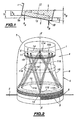
- a container 1 in the form of a bowl whose bottom 2 is perforated with openings 3 and has a circular shape of axis XX normally vertical.
- the openings 3 may in particular be circular holes, and, unless otherwise indicated, it will be assumed that this is so and that the holes are all identical.
- the openings 3 situated at the same distance r from this axis provide different liquid flow rates, because they are surmounted by liquid heights different.
- the high opening 3A provides a flow Q A proportional to h - r sina
- the low opening 3B provides a flow Q B proportional to h + r sina
- the flow difference may be of the order of 10 % or more, which is unacceptable to ensure satisfactory operation of the column.
- the Figures 2 and 3 represent a liquid dispenser 4 which comprises the container 1 and which, on the contrary, ensures a distribution of substantially uniform liquid over the entire section of the distillation column 5 regardless of the inclination, under the aforementioned oscillation conditions.
- the container 1 could also be replaced by a series of perforated bottom chutes, or by a sheet of perforated tubes.
- the distillation column 5 comprises, at its upper part, a cylindrical shell 6 of axis XX, and an upper dome 7.
- the column is embedded on a floating structure schematized in S on the Figure 2 .
- the upper distillation section 8 of the column consists of a cross-corrugated packing.
- such a lining comprises a superposition of sections or packs 9 of corrugated-crossed packing, each of which has the shape of a cylindrical slab occupying the entire section of the column.
- Each pack 9 consists of a stack of oblique wave corrugated strips.
- Each band has a vertical general plane, all the bands have the same height, and the waves are alternately inclined in one direction and the other from one band to the next. Thus, the waves of the adjacent bands touch in a large number of points of intersection.
- the packs 9 are angularly offset by 90 ° from one pack to the next with respect to the general axis of the column.
- the ratio of the diameters is typically 1 to 6.
- the bottom 2 of the container 1 has as many openings 3 that it is desired liquid distribution points on the upper pack 9, typically 1000 to 3000 openings for a column about 4 m in diameter.
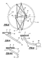
- the distributor 4 further comprises a rectilinear tube 10 by opening 3.
- Each tube 10 has an upper inlet orifice 11 disposed just below the corresponding opening 3, and a lower outlet orifice 12 disposed just above the upper surface. 13 of the 9 upper pack. If r and R respectively denote the distances to the axis XX of the orifices 11 and 12, then R> r .
- the point 12 is angularly offset by 90 °, about the axis XX, relative to the point 11, as can be seen on the Figures 2 and 3 .
- the openings 3 are arranged in a series of concentric rings. At each crown 14 of mean radius r is associated a ring 15 of average radius R of the surface 13, and all the tubes which connect these two rings are inclined in the same direction. Thus, all of the tubes 10 associated with two homologous rings 14 and 15 given data constitute generators of a hyperboloid of revolution 16.
- the tubes 10 are inclined in opposite directions, thus forming two hyperboloid of revolution 16 and 116 nested one inside the other.
- the hyperboloid 116 schematized on the Figure 2 corresponds to crowns 114 and 115 located immediately inside the rings 14 and 15 above.
- the set of tubes 10 in this way forms a stack of hyperboloids of revolution whose generatrices are alternately inclined in both directions.
- substantially diametrically opposite pairs of openings belonging to two adjacent rings 14, 114 are connected by their tubes 10 to two points 12, 112, adjacent to each other, since they are located substantially in the same half-plane. radial passing through the axis XX and belonging to two crowns 15, 115 adjacent.
- the zone of the surface 13 situated just below the points 12 and 112 receives the sum of the flow rates resulting from a pair of substantially diametrically opposite openings of the container 1, which sum is practically constant for all the pairs of openings.
- the area of the zone in question is small enough so that the two flows are well remixed by the corrugated-crossed packing, so that the distribution of the liquid over the entire surface 13 remains permanently uniform despite oscillations of the XX axis.
- the structure of the distributor 1 passes without significant pressure drop the rising gas, between the tubes 10 and around the container 1.
- the Figure 4 represents a rectilinear tube 10, provided at its inlet with a funnel 17 which guarantees the collection of all the liquid coming from the corresponding opening 3. All the funnels 17 are fixed in place by means of a plate 18 with holes of the same diameter as the container 1, arranged at a small distance below the bottom 2 and fixed thereto.
- the curved tubes associated with two homologous rings are wound so as to generate around the axis X-X a sleeve-shaped surface.
- the set of curved tubes forms a series of such surfaces nested one inside the other, the winding directions of the tubes being inverted from one surface to the next.
- the variant of the Figure 5A differs from the previous one on the one hand by the suppression of the watering head 22, and on the other hand by the shape of the tube 10.
- it comprises an inclined main rectilinear part, like that of the Figure 4 , and is bent to form two end portions also rectilinear but vertical.
- the Figure 6 illustrates another way of correcting the effects of column inclination by obtaining a liquid distribution which anticipates the distribution defects in the lining due to inclination. Indeed, under the effect of inclination, the liquid tends to accumulate on one side of the column, while the other side dries gradually. It may therefore be advisable to feed the drying side with a larger liquid flow and the opposite side with a lower flow rate.
- tubes 10A and 10B associated with substantially diametrically opposed openings 3A and 3B lead to points 12A, 12B of the surface 13 which are also substantially diametrically opposed but which are inverted with respect to the two openings.
- the point 12A (respectively 12B) is substantially in the same radial half-plane, with respect to the axis XX, as the opening 3B (respectively 3A). This arrangement therefore makes it possible to water more significantly the packing areas that may dry out under the effect of inclination.
- point 12A is angularly offset by 180 ° around XX 'with respect to point 11A.
- the mode of correction or "over-compensation" of the flows schematized on-the Figure 6 can also be applied to the transport of the liquid from the container 1 to the containers 101 or the compartments 123 in the case of a two-stage distributor.
- each opening 3 instead of consisting of a single perforation of relatively large diameter, may be constituted by a group of perforations 203 of smaller diameter close to each other.
- the resulting advantage is to allow to obtain a given flow rate of liquid with a height H2 ( Figure 9 ) less than that H 1 necessary in the case of a single perforation ( Figure 8 ), which creates a disruptive vortex effect.
- the diameter of the multiple perforations 203 must remain sufficient to avoid any risk of clogging by impurities contained in the liquid to be distilled.
- the invention also applies to the distribution of reflux liquid in a fixed column but whose axis is not perfectly vertical.
- cross-corrugated packing as used herein also includes such packing, as well as any similar packing.
Landscapes
- Chemical & Material Sciences (AREA)
- Chemical Kinetics & Catalysis (AREA)
- Vaporization, Distillation, Condensation, Sublimation, And Cold Traps (AREA)
- Feeding, Discharge, Calcimining, Fusing, And Gas-Generation Devices (AREA)
- Containers And Packaging Bodies Having A Special Means To Remove Contents (AREA)
Claims (14)
- Flüssigkeitsverteiler für eine Destillationskolonne, umfassend ein Hauptvolumen (1), das im unteren Teil Ausgangsöffnungen (3) aufweist, die in einer Zone (2) verteilt sind; umfassend mehrere Transportelemente (10; 110), die jeweils dazu vorgesehen sind, die Flüssigkeit, die aus mindestens einer Öffnung (3) kommt, durch Schwerkraft zu einem Lieferpunkt (12, 112; 101, 123) zu befördern, der nicht lotrecht zu dieser Öffnung liegt, wobei der Flüssigkeitsstrom, der von jeder Öffnung oder Gruppe von Öffnungen (3A, 3B) des Hauptvolumens kommt, von dem entsprechenden Transportelement (10A, 10B) derart befördert wird, dass sein Durchsatz stärker wird, wenn die besprühte Zone unter Einwirkung der Neigung höher liegt, und im umgekehrten Fall schwächer wird, und das Transportelement (10A, 10B), das jeder Öffnung (3A, 3B) zugeordnet ist, zu einem Lieferpunkt führt, der sich winkelig in einem Winkel von 180° zu dieser Öffnung in Bezug zur Mittelachse (X-X) des Verteilers befindet, dadurch gekennzeichnet, dass jedes Transportelement (10; 110) eine nach oben in Form einer Rutsche offene oder in Form einer Röhre geschlossene Leitung umfasst, wobei diese Leitung gerade, an einer oder mehreren Stellen geknickt oder gebogen ist.
- Verteiler nach Anspruch 1, dadurch gekennzeichnet, dass jede Öffnung (3) aus einer einzigen Perforation oder aus mehreren nebeneinander liegenden Perforationen (203) besteht.
- Verteiler nach Anspruch 1 oder 2, dadurch gekennzeichnet, dass das Transportorgan (10; 110) ein Eingangsende (11) umfasst, das unterhalb und lotrecht unter der Öffnung (3) liegt und vom Ausgangsende von letzterer beabstandet ist.
- Verteiler nach einem der Ansprüche 1 bis 3, dadurch gekennzeichnet, dass das Transportorgan an seinem Ausgangsende eine Vorrichtung (22) zum Besprühen einer Sprühzone besitzt, deren Fläche größer ist als die Öffnung (3).
- Verteiler nach einem der Ansprüche 1 bis 4, dadurch gekennzeichnet, dass er mehrere Transportorgane umfasst, und dadurch, dass der mittlere Durchmesser der Zone (2) kleiner ist als der mittlere Durchmesser der Fläche, die die Ausgangsöffnungen (12) der Transportorgane enthält, wobei das Verhältnis der Durchmesser insbesondere größer als 1 und kleiner als etwa 6 ist.
- Verteiler nach einem der Ansprüche 1 bis 5, dadurch gekennzeichnet, dass er mehrere Transportorgane umfasst, dass die Öffnungen (3) des Hauptvolumens in einer ersten in etwa horizontalen Ebene (2) in konzentrischen, in etwa kreisförmigen Kränzen angeordnet sind, die jeweils einem Kranz Ausgangsöffnungen (12) entsprechen, der in einer zweiten in etwa horizontalen Ebene unter der ersten Ebene angeordnet ist und die gleiche Anzahl Lieferpunkte umfasst, und dadurch, dass ein Transportorgan (10) jeden Punkt des ersten Kranzes mit einem assoziierten Punkt des zweiten Kranzes verbindet.
- Verteiler nach Anspruch 6, dadurch gekennzeichnet, dass die Paare assoziierter Punkte winkelig um einen gleichen Winkel um die Achse (X-X) der Kränze versetzt sind, wobei die Transportorgane (10), die zwei Kränze assoziieren, eine Manteloberfläche (16, 116) in Form eine Stutzens bilden und die Einheit der Transportorgane eine Reihe solcher Manteloberflächen bildet, die ineinander verschachtelt sind.
- Verteiler nach Anspruch 7, dadurch gekennzeichnet, dass die winkelige Versetzung von einer Manteloberfläche (16, 116) zur anderen umgekehrt ist.
- Verteiler nach einem der Ansprüche 1 bis 8, dadurch gekennzeichnet, dass er mehrere Transportorgane umfasst, und dadurch, dass die Ausgangsenden der Transportorgane (10, 110) die Flüssigkeit an mehrere Sekundärverteilbehälter (101; 123) mit perforiertem Boden (102) liefern.
- Destillationskolonne, dadurch gekennzeichnet, dass sie auf mindestens einem Niveau einen Flüssigkeitsverteiler (4) nach einem der Ansprüche 1 bis 9 umfasst, der über einen Destillationsabschnitt (8) ragt.
- Destillationskolonne nach Anspruch 10, dadurch gekennzeichnet, dass der Destillationsabschnitt (8) wellig-verkreuzt ausgekleidet ist.
- Destillationskolonne nach Anspruch 10 oder 11, dadurch gekennzeichnet, dass der Verteiler (4) der Kopfverteiler der Kolonne (5) ist, wobei das Hauptvolumen (1) mindestens teilweise im oberen Dom (7) der Kolonne untergebracht ist.
- Destillationskolonne nach einem der Ansprüche 10 bis 12, dadurch gekennzeichnet, dass die Transportorgane (10) die Flüssigkeit direkt auf den Destillationsabschnitt (8) liefern.
- Destillationskolonne nach einem der Ansprüche 10 bis 13, dadurch gekennzeichnet, dass sie auf einem schwimmenden Aufbau (S) mitgeführt wird, wie zum Beispiel auf einer schwimmenden Erdölplattform oder auf einer Bohrinsel.
Applications Claiming Priority (3)
| Application Number | Priority Date | Filing Date | Title |
|---|---|---|---|
| FR9714377 | 1997-11-17 | ||
| FR9714377A FR2771017B1 (fr) | 1997-11-17 | 1997-11-17 | Distributeur de liquide pour colonne de distillation non verticale, et colonne de distillation ainsi equipee |
| PCT/FR1998/002386 WO1999025445A1 (fr) | 1997-11-17 | 1998-11-09 | Distributeur de liquide pour colonne de distillation non verticale, et colonne de distillation ainsi equipee |
Publications (3)
| Publication Number | Publication Date |
|---|---|
| EP1032464A1 EP1032464A1 (de) | 2000-09-06 |
| EP1032464B1 EP1032464B1 (de) | 2003-07-02 |
| EP1032464B2 true EP1032464B2 (de) | 2009-02-25 |
Family
ID=9513440
Family Applications (1)
| Application Number | Title | Priority Date | Filing Date |
|---|---|---|---|
| EP98958949A Expired - Lifetime EP1032464B2 (de) | 1997-11-17 | 1998-11-09 | Flüssigkeitsverteiler für nicht senkrechte destillationskolonne und damit ausgerüstete destillationskolonne |
Country Status (13)
| Country | Link |
|---|---|
| US (1) | US6338774B1 (de) |
| EP (1) | EP1032464B2 (de) |
| JP (1) | JP2001523541A (de) |
| CN (1) | CN1147339C (de) |
| AR (1) | AR017625A1 (de) |
| AU (1) | AU1491199A (de) |
| BR (1) | BR9814646A (de) |
| CA (1) | CA2310124A1 (de) |
| DE (1) | DE69816111T2 (de) |
| FR (1) | FR2771017B1 (de) |
| NO (1) | NO20002531L (de) |
| TW (1) | TW438614B (de) |
| WO (1) | WO1999025445A1 (de) |
Families Citing this family (17)
| Publication number | Priority date | Publication date | Assignee | Title |
|---|---|---|---|---|
| FI106296B (fi) * | 1998-11-09 | 2001-01-15 | Amsco Europ Inc Suomen Sivulii | Menetelmä ja laite haihdutettavan veden käsittelemiseksi |
| DE19957458A1 (de) * | 1999-11-29 | 2001-05-31 | Bayer Ag | Strangverdampfer |
| US6663751B2 (en) * | 2000-07-17 | 2003-12-16 | Analab (Sarl) | Device for evaporation and condensation in confined environment |
| US6907751B2 (en) * | 2002-07-30 | 2005-06-21 | Air Products And Chemicals, Inc. | Liquid distributor |
| EP1386649A1 (de) * | 2002-07-30 | 2004-02-04 | Air Products And Chemicals, Inc. | Flüssigkeitsverteiler |
| US7087139B1 (en) * | 2002-08-23 | 2006-08-08 | Fina Technology, Inc. | Apparatus and method for removal of volatiles from a mass processable polymer |
| DE102007019816A1 (de) * | 2007-04-26 | 2008-10-30 | Linde Ag | Sammler-Verteiler-Kombination |
| DE102011103634A1 (de) * | 2011-06-08 | 2012-12-13 | Linde Aktiengesellschaft | Flüssigkeitsverteiler |
| EP2790804B1 (de) * | 2011-12-16 | 2019-10-16 | Air Products and Chemicals, Inc. | Flüssigkeitsverteiler mit einem mischer |
| US9630123B2 (en) | 2011-12-16 | 2017-04-25 | Air Products And Chemicals, Inc. | Liquid distributor with a mixer |
| FR2989595B1 (fr) | 2012-04-18 | 2014-04-11 | IFP Energies Nouvelles | Plateau distributeur a cloisons pour colonne de contact gaz/liquide offshore |
| FR2989594B1 (fr) | 2012-04-18 | 2015-04-24 | IFP Energies Nouvelles | Plateau distributeur pour colonne de contact gaz/liquide offshore |
| FR3026019B1 (fr) | 2014-09-24 | 2017-05-12 | Ifp Energies Now | Plateau distributeur compact pour les colonnes de contact gaz/liquide en mer |
| FR3030295B1 (fr) | 2014-12-17 | 2018-09-28 | IFP Energies Nouvelles | Plateau distributeur compact pour les colonnes de contact gaz/liquide en mer |
| FR3065171B1 (fr) * | 2017-04-13 | 2021-02-12 | Saipem Sa | Dispositif de double distribution de liquide utile dans une colonne de fractionnement ou de lavage sur un support flottant |
| FR3075064B1 (fr) | 2017-12-19 | 2019-12-27 | IFP Energies Nouvelles | Plateau distributeur a compartiments et cheminees gaz de meme forme pour colonne de contact gaz/liquide offshore |
| FR3134993B3 (fr) | 2022-06-27 | 2024-06-28 | Air Liquide | Distributeur de liquide pour colonne de traitement |
Family Cites Families (9)
| Publication number | Priority date | Publication date | Assignee | Title |
|---|---|---|---|---|
| DE1113680B (de) * | 1959-12-22 | 1961-09-14 | Hydrocarbon Mineraloel G M B H | Vorrichtung zur Fluessigkeitsverteilung in nicht ortsfesten Fuellkoerperkolonnen |
| JPS5527045A (en) * | 1978-08-15 | 1980-02-26 | Mitsubishi Heavy Ind Ltd | Plate structure in gas liquid contact equipment |
| CH642566A5 (de) * | 1979-10-25 | 1984-04-30 | Sulzer Ag | Trogartige vorrichtung zum sammeln und verteilen der fluessigkeit in einer gegenstromkolonne. |
| US4776989A (en) * | 1983-09-19 | 1988-10-11 | The Dow Chemical Company | Method and apparatus for liquid feed to liqiud distributors in fluid-liquid contacting towers |
| US5381839A (en) * | 1992-07-22 | 1995-01-17 | Dowd; Tracy J. | Liquid disburser device |
| US5593734A (en) * | 1993-03-12 | 1997-01-14 | Eastman Kodak Company | Multiple inlet flow distributor for liquids |
| FR2711545B1 (fr) * | 1993-10-29 | 1995-12-22 | Air Liquide | Distributeur de liquide pour dispositif d'échange de chaleur et de matière, colonne de distillation comprenant un tel distributeur, et utilisation d'une telle colonne pour la distillation de l'air. |
| US5919405A (en) * | 1997-10-23 | 1999-07-06 | Monsanto Company | Fluid distribution system for an absorption tower |
| FR2771019B1 (fr) * | 1997-11-17 | 2000-02-04 | Air Liquide | Distributeur de liquide pour colonne de distillation, et colonne de distillation correspondante |
-
1997
- 1997-11-17 FR FR9714377A patent/FR2771017B1/fr not_active Expired - Fee Related
-
1998
- 1998-11-09 DE DE69816111T patent/DE69816111T2/de not_active Expired - Fee Related
- 1998-11-09 JP JP2000520875A patent/JP2001523541A/ja active Pending
- 1998-11-09 CA CA002310124A patent/CA2310124A1/fr not_active Abandoned
- 1998-11-09 CN CNB988123428A patent/CN1147339C/zh not_active Expired - Fee Related
- 1998-11-09 AU AU14911/99A patent/AU1491199A/en not_active Abandoned
- 1998-11-09 WO PCT/FR1998/002386 patent/WO1999025445A1/fr not_active Ceased
- 1998-11-09 EP EP98958949A patent/EP1032464B2/de not_active Expired - Lifetime
- 1998-11-09 BR BR9814646-7A patent/BR9814646A/pt not_active IP Right Cessation
- 1998-11-13 TW TW087118862A patent/TW438614B/zh not_active IP Right Cessation
- 1998-11-16 AR ARP980105787A patent/AR017625A1/es unknown
- 1998-11-17 US US09/193,119 patent/US6338774B1/en not_active Expired - Fee Related
-
2000
- 2000-05-16 NO NO20002531A patent/NO20002531L/no not_active Application Discontinuation
Also Published As
| Publication number | Publication date |
|---|---|
| JP2001523541A (ja) | 2001-11-27 |
| NO20002531D0 (no) | 2000-05-16 |
| WO1999025445A1 (fr) | 1999-05-27 |
| BR9814646A (pt) | 2000-10-03 |
| EP1032464A1 (de) | 2000-09-06 |
| EP1032464B1 (de) | 2003-07-02 |
| FR2771017B1 (fr) | 2000-02-04 |
| DE69816111D1 (de) | 2003-08-07 |
| AR017625A1 (es) | 2001-09-12 |
| NO20002531L (no) | 2000-07-11 |
| AU1491199A (en) | 1999-06-07 |
| TW438614B (en) | 2001-06-07 |
| FR2771017A1 (fr) | 1999-05-21 |
| DE69816111T2 (de) | 2004-04-15 |
| CA2310124A1 (fr) | 1999-05-27 |
| CN1282266A (zh) | 2001-01-31 |
| CN1147339C (zh) | 2004-04-28 |
| US6338774B1 (en) | 2002-01-15 |
Similar Documents
| Publication | Publication Date | Title |
|---|---|---|
| EP1032464B2 (de) | Flüssigkeitsverteiler für nicht senkrechte destillationskolonne und damit ausgerüstete destillationskolonne | |
| EP1147809B1 (de) | Vorrichtung, die einen Wasserstrahlregler enthält, zur Verteilung einer mehrphasigen Mischung über ein Festbett | |
| CA2032199C (fr) | Distributeur de fluides pour colonne d'echange de chaleur et de matiere, notamment a garnissage, et colonne munie d'un tel distributeur | |
| EP1147808B1 (de) | Mehrzweckige Teilmontage, die den Kontakt, die Verteilung und den Wärme- und/oder Materialaustausch in mindestens eine Gasphase sowie eine Flüssigphase sicherstellt | |
| EP2739383A1 (de) | Schale zur abgabe von einem gas und einer flüssigkeit, reaktor mit derartiger schale und verwendung besagter schale | |
| FR2484269A1 (fr) | Distributeur de liquide a faible debit pour tour de contact entre du liquide et du gaz | |
| EP3368172B1 (de) | Säule für wärme- und/oder massenaustausch zwischen zwei flüssigkeiten mit einer sammelschale und gasmischvorrichtung | |
| EP1446221B1 (de) | Vorrichtung zum verteilen einer mehrphasenmischung in einem granulat-festbett durch einen strahlverteiler mit aufkantung | |
| WO2006097590A2 (fr) | Dispositif pour le melange et la repartition d'un gaz et d'un liquide en amont d'un lit granulaire | |
| WO1999054036A1 (fr) | Structure maritime flottante perfectionnee | |
| FR2827523A1 (fr) | Dispositif de fractionnement possedant une grille de faible surface specifique au-dessus d'un plancher de plateau | |
| EP3609590A1 (de) | Doppelflüssigkeitsverteilungsvorrichtung zur verwendung insbesondere in einer vorrichtung, in der eine flüssige phase unter schwerkraft fliesst | |
| EP1034018B1 (de) | Flüssigkeitsverteiler für oszillierende destillationskolonne und eine solche kolonne | |
| EP1034019B1 (de) | Flüssigkeitsverteiler für oszillierende destillationskolonne und eine solche destillationskolonne | |
| EP0650748B1 (de) | Flüssigkeitsverteiler für einen Wärmetauscher und Stoffaustauscher, Distillationskolonne mit einem solchen Verteiler und Anwendung einer derartigen Kolonne zur Luftzerlegung | |
| EP1152967B1 (de) | Vorrichtung zum dispergieren von schüttgut im innenraum eines behälters | |
| CA2751523A1 (fr) | Dispositif de distribution d'un melange polyphasique comportant un plateau brise-jet perfore avec differents types de trous | |
| FR2553300A1 (fr) | Procede pour uniformiser un courant ascendant de gaz et de liquide dans un reacteur a lit fluidise et grille etagee de distribution d'ecoulement pour sa mise en oeuvre | |
| EP0251839B1 (de) | Fallstromverdampfer, ausgerüstet mit einem Flüssigkeitsverteiler | |
| EP2425881A1 (de) | Verteilungsvorrichtung einer mehrphasigen Mischbatterie, die eine Strahlteilungsplatte mit Trennelement enthält | |
| FR3113611A1 (fr) | Distributeur filaire de liquide pour colonne a garnissage | |
| FR2964326A1 (fr) | Dispositif de distribution d'un melange polyphasique comportant un plateau brise-jet perfore avec differents types de trous | |
| FR2527937A1 (fr) | Dispositif d'absorption d'un gaz tel que nh3, so2 ou la vapeur d'eau, par un liquide tel que l'eau |
Legal Events
| Date | Code | Title | Description |
|---|---|---|---|
| PUAI | Public reference made under article 153(3) epc to a published international application that has entered the european phase |
Free format text: ORIGINAL CODE: 0009012 |
|
| 17P | Request for examination filed |
Effective date: 20000619 |
|
| AK | Designated contracting states |
Kind code of ref document: A1 Designated state(s): DE DK FR GB NL SE |
|
| RAP1 | Party data changed (applicant data changed or rights of an application transferred) |
Owner name: L'AIR LIQUIDE, S.A. A DIRECTOIRE ET CONSEIL DE SUR |
|
| 17Q | First examination report despatched |
Effective date: 20020508 |
|
| GRAH | Despatch of communication of intention to grant a patent |
Free format text: ORIGINAL CODE: EPIDOS IGRA |
|
| GRAH | Despatch of communication of intention to grant a patent |
Free format text: ORIGINAL CODE: EPIDOS IGRA |
|
| GRAA | (expected) grant |
Free format text: ORIGINAL CODE: 0009210 |
|
| AK | Designated contracting states |
Designated state(s): DE DK FR GB NL SE |
|
| PG25 | Lapsed in a contracting state [announced via postgrant information from national office to epo] |
Ref country code: NL Free format text: LAPSE BECAUSE OF FAILURE TO SUBMIT A TRANSLATION OF THE DESCRIPTION OR TO PAY THE FEE WITHIN THE PRESCRIBED TIME-LIMIT Effective date: 20030702 |
|
| REG | Reference to a national code |
Ref country code: GB Ref legal event code: FG4D Free format text: NOT ENGLISH |
|
| REF | Corresponds to: |
Ref document number: 69816111 Country of ref document: DE Date of ref document: 20030807 Kind code of ref document: P |
|
| PG25 | Lapsed in a contracting state [announced via postgrant information from national office to epo] |
Ref country code: SE Free format text: LAPSE BECAUSE OF FAILURE TO SUBMIT A TRANSLATION OF THE DESCRIPTION OR TO PAY THE FEE WITHIN THE PRESCRIBED TIME-LIMIT Effective date: 20031002 Ref country code: DK Free format text: LAPSE BECAUSE OF FAILURE TO SUBMIT A TRANSLATION OF THE DESCRIPTION OR TO PAY THE FEE WITHIN THE PRESCRIBED TIME-LIMIT Effective date: 20031002 |
|
| GBT | Gb: translation of ep patent filed (gb section 77(6)(a)/1977) | ||
| NLV1 | Nl: lapsed or annulled due to failure to fulfill the requirements of art. 29p and 29m of the patents act | ||
| PLBI | Opposition filed |
Free format text: ORIGINAL CODE: 0009260 |
|
| PLBQ | Unpublished change to opponent data |
Free format text: ORIGINAL CODE: EPIDOS OPPO |
|
| PLAX | Notice of opposition and request to file observation + time limit sent |
Free format text: ORIGINAL CODE: EPIDOSNOBS2 |
|
| 26 | Opposition filed |
Opponent name: LINDE AKTIENGESELLSCHAFT, WIESBADEN Effective date: 20030401 |
|
| PLAX | Notice of opposition and request to file observation + time limit sent |
Free format text: ORIGINAL CODE: EPIDOSNOBS2 |
|
| PLAS | Information related to reply of patent proprietor to notice(s) of opposition deleted |
Free format text: ORIGINAL CODE: EPIDOSDOBS3 |
|
| PLBB | Reply of patent proprietor to notice(s) of opposition received |
Free format text: ORIGINAL CODE: EPIDOSNOBS3 |
|
| RDAF | Communication despatched that patent is revoked |
Free format text: ORIGINAL CODE: EPIDOSNREV1 |
|
| APBP | Date of receipt of notice of appeal recorded |
Free format text: ORIGINAL CODE: EPIDOSNNOA2O |
|
| APAH | Appeal reference modified |
Free format text: ORIGINAL CODE: EPIDOSCREFNO |
|
| APBQ | Date of receipt of statement of grounds of appeal recorded |
Free format text: ORIGINAL CODE: EPIDOSNNOA3O |
|
| APAH | Appeal reference modified |
Free format text: ORIGINAL CODE: EPIDOSCREFNO |
|
| RAP2 | Party data changed (patent owner data changed or rights of a patent transferred) |
Owner name: L'AIR LIQUIDE, SOCIETE ANONYME POUR L'ETUDE ET L'E |
|
| RAP2 | Party data changed (patent owner data changed or rights of a patent transferred) |
Owner name: L'AIR LIQUIDE, SOCIETE ANONYME POUR L'ETUDE ET L'E |
|
| APBU | Appeal procedure closed |
Free format text: ORIGINAL CODE: EPIDOSNNOA9O |
|
| PLAY | Examination report in opposition despatched + time limit |
Free format text: ORIGINAL CODE: EPIDOSNORE2 |
|
| PLBC | Reply to examination report in opposition received |
Free format text: ORIGINAL CODE: EPIDOSNORE3 |
|
| PUAH | Patent maintained in amended form |
Free format text: ORIGINAL CODE: 0009272 |
|
| STAA | Information on the status of an ep patent application or granted ep patent |
Free format text: STATUS: PATENT MAINTAINED AS AMENDED |
|
| PGFP | Annual fee paid to national office [announced via postgrant information from national office to epo] |
Ref country code: DE Payment date: 20081119 Year of fee payment: 11 |
|
| 27A | Patent maintained in amended form |
Effective date: 20090225 |
|
| AK | Designated contracting states |
Kind code of ref document: B2 Designated state(s): DE DK FR GB NL SE |
|
| PGFP | Annual fee paid to national office [announced via postgrant information from national office to epo] |
Ref country code: FR Payment date: 20081013 Year of fee payment: 11 |
|
| PGFP | Annual fee paid to national office [announced via postgrant information from national office to epo] |
Ref country code: GB Payment date: 20081022 Year of fee payment: 11 |
|
| GBPC | Gb: european patent ceased through non-payment of renewal fee |
Effective date: 20091109 |
|
| PG25 | Lapsed in a contracting state [announced via postgrant information from national office to epo] |
Ref country code: DE Free format text: LAPSE BECAUSE OF NON-PAYMENT OF DUE FEES Effective date: 20100601 |
|
| PG25 | Lapsed in a contracting state [announced via postgrant information from national office to epo] |
Ref country code: GB Free format text: LAPSE BECAUSE OF NON-PAYMENT OF DUE FEES Effective date: 20091109 |
|
| REG | Reference to a national code |
Ref country code: FR Ref legal event code: ST Effective date: 20110819 |
|
| PG25 | Lapsed in a contracting state [announced via postgrant information from national office to epo] |
Ref country code: FR Free format text: LAPSE BECAUSE OF NON-PAYMENT OF DUE FEES Effective date: 20091130 |