EP1032776B1 - Direkt- fluidischer viskositätsdämpfer - Google Patents
Direkt- fluidischer viskositätsdämpfer Download PDFInfo
- Publication number
- EP1032776B1 EP1032776B1 EP98958442A EP98958442A EP1032776B1 EP 1032776 B1 EP1032776 B1 EP 1032776B1 EP 98958442 A EP98958442 A EP 98958442A EP 98958442 A EP98958442 A EP 98958442A EP 1032776 B1 EP1032776 B1 EP 1032776B1
- Authority
- EP
- European Patent Office
- Prior art keywords
- fluid
- structural apparatus
- tubular member
- outer tubular
- structural
- Prior art date
- Legal status (The legal status is an assumption and is not a legal conclusion. Google has not performed a legal analysis and makes no representation as to the accuracy of the status listed.)
- Expired - Lifetime
Links
Images

Classifications
-
- F—MECHANICAL ENGINEERING; LIGHTING; HEATING; WEAPONS; BLASTING
- F16—ENGINEERING ELEMENTS AND UNITS; GENERAL MEASURES FOR PRODUCING AND MAINTAINING EFFECTIVE FUNCTIONING OF MACHINES OR INSTALLATIONS; THERMAL INSULATION IN GENERAL
- F16F—SPRINGS; SHOCK-ABSORBERS; MEANS FOR DAMPING VIBRATION
- F16F9/00—Springs, vibration-dampers, shock-absorbers, or similarly-constructed movement-dampers using a fluid or the equivalent as damping medium
- F16F9/32—Details
- F16F9/50—Special means providing automatic damping adjustment, i.e. self-adjustment of damping by particular sliding movements of a valve element, other than flexions or displacement of valve discs; Special means providing self-adjustment of spring characteristics
- F16F9/52—Special means providing automatic damping adjustment, i.e. self-adjustment of damping by particular sliding movements of a valve element, other than flexions or displacement of valve discs; Special means providing self-adjustment of spring characteristics in case of change of temperature
-
- F—MECHANICAL ENGINEERING; LIGHTING; HEATING; WEAPONS; BLASTING
- F16—ENGINEERING ELEMENTS AND UNITS; GENERAL MEASURES FOR PRODUCING AND MAINTAINING EFFECTIVE FUNCTIONING OF MACHINES OR INSTALLATIONS; THERMAL INSULATION IN GENERAL
- F16F—SPRINGS; SHOCK-ABSORBERS; MEANS FOR DAMPING VIBRATION
- F16F9/00—Springs, vibration-dampers, shock-absorbers, or similarly-constructed movement-dampers using a fluid or the equivalent as damping medium
- F16F9/10—Springs, vibration-dampers, shock-absorbers, or similarly-constructed movement-dampers using a fluid or the equivalent as damping medium using liquid only; using a fluid of which the nature is immaterial
- F16F9/103—Devices with one or more members moving linearly to and fro in chambers, any throttling effect being immaterial, i.e. damping by viscous shear effect only
-
- F—MECHANICAL ENGINEERING; LIGHTING; HEATING; WEAPONS; BLASTING
- F16—ENGINEERING ELEMENTS AND UNITS; GENERAL MEASURES FOR PRODUCING AND MAINTAINING EFFECTIVE FUNCTIONING OF MACHINES OR INSTALLATIONS; THERMAL INSULATION IN GENERAL
- F16F—SPRINGS; SHOCK-ABSORBERS; MEANS FOR DAMPING VIBRATION
- F16F2230/00—Purpose; Design features
- F16F2230/0052—Physically guiding or influencing
-
- F—MECHANICAL ENGINEERING; LIGHTING; HEATING; WEAPONS; BLASTING
- F16—ENGINEERING ELEMENTS AND UNITS; GENERAL MEASURES FOR PRODUCING AND MAINTAINING EFFECTIVE FUNCTIONING OF MACHINES OR INSTALLATIONS; THERMAL INSULATION IN GENERAL
- F16F—SPRINGS; SHOCK-ABSORBERS; MEANS FOR DAMPING VIBRATION
- F16F2230/00—Purpose; Design features
- F16F2230/10—Enclosure elements, e.g. for protection
Definitions
- This invention relates to the field of vibration damping and isolation.
- the present invention is a passive damping and isolation system that uses direct shear of a viscous fluid to dampen vibration energy.
- a precision structural system carrying a load such as a telescope
- a load such as a telescope
- Such vibrations may be contributed to the structural system by components or assemblies of the system itself.
- reaction wheel assemblies used to point the telescope Since such a precision structural system tends to have little inherent damping, these vibrations can lead to serious performance degradation. Therefore, an efficient means of damping and isolating, in a controlled manner, the load carried by a precision structural system is of considerable importance.
- fluid dampers typically operate by displacing a viscous fluid from one fluid reservoir to another fluid reservoir through a restrictive passage. Shearing of the viscous fluid as it flows through the restrictive passage provides a damping force that is proportional to velocity. This requires that the restrictive passage be relatively long with respect to its cross-section so that the damping force is proportional to velocity, and not due to restrictive passage entrance and exit fluid pressure drops or turbulent to laminar flow regimes. In addition, the mass of the viscous fluid within the restrictive passage must be minimized to prevent non-linear fluid surge effects.
- Patent EP-A-0339 113 is an example of such a system
- one of the fluid reservoirs must be pressurized with respect to the other fluid reservoir to force the viscous fluid to flow from one reservoir to the other through the restrictive passage.
- This pressurization must be contained by the fluid damper structure for the fluid damper to operate consistently over its useful life.
- hermetic seals must be used. These hermetic seals must be designed to withstand the internal fluid pressure of the damper, and may add volumetric compliance to the damping and isolation system. This volumetric compliance may be beneficial in isolation systems but reduces the performance of pure dampers.
- damping and isolation systems there is a need for improved damping and isolation systems.
- a damping and isolation system that will virtually eliminate system design concerns related to the damping force provided by the flow of viscous fluid through the restrictive passage.
- a damping and isolation system that will essentially eliminate system operation concerns of viscous fluid leakage related to pressurization of the viscous fluid during operation of the damping and isolation system.
- the damping and isolation system should surmount these concerns while maintaining a weight, size and complexity efficient structure.
- the present invention provides a structural apparatus as defined in Claim 1.
- the structural apparatus may include the features of any one or more of dependent Claims 2 to 16.
- the present invention is a structural apparatus.
- the structural apparatus includes a passive damping mechanism having an outer tubular member and an inner member positioned within the outer member.
- the inner and outer members are linearly movable relative to one another upon application of forces to the structural apparatus.
- the inner member is spaced from the outer member by a fluid shear gap that is filled with a viscous fluid. Fluid pressure of the viscous fluid remains constant while the viscous fluid dissipates the forces by direct fluid shear upon relative linear movement of the outer and inner members.
- This structural apparatus having a passive damping mechanism virtually eliminates concerns of viscous fluid leakage related to pressurization of the viscous fluid during operation of the passive damping mechanism. Viscous fluid leakage concerns have been obviated since the fluid pressure of the viscous fluid remains constant while the viscous fluid dissipates the forces by direct fluid shear upon relative linear movement of the outer and inner members. Moreover, prior art damping system design concerns related to the damping force provided by the flow of viscous fluid through a restrictive passage have been eliminated, since the damping mechanism of the present invention operates via direct fluid shear rather than by the fluid shear resulting from forcing a viscous fluid through a restrictive passage. In addition, this structural apparatus having a passive damping mechanism surmounts these concerns while maintaining a weight, size and complexity efficient structure.
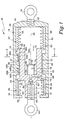
- FIG. 1 is a side sectional view of a vibration damping and isolation apparatus in accordance with the present invention.
- FIG. 2 is a cross sectional view taken along line 2-2 in FIG. 1.
- the damping and isolation apparatus 10 comprises a damping mechanism 12 and a thermal compensation mechanism 14.
- the damping mechanism 12 includes an outer tubular member 16 having an end cap 18 at a first end 20 and an inwardly extending radial flange 22 at a second end 24.
- the damping mechanism 12 further includes an inner member 25 defined by an inner tubular segment 26 having first and second outwardly extending radial flanges 28 and 30 at first and second end portions 32 and 34, respectively.
- the inner member 25 is further defined by an inner cylindrical shaft segment 36 that extends axially outwardly from the second end portion 34 of the inner tubular segment 26.
- the inner tubular segment 26 of the inner member 25 is spaced from the outer tubular member 16 by a fluid shear gap 37.
- First and second end fittings 38 and 40 are threadably received within threaded openings 42 and 44 of the end cap 18 of the outer tubular member 16 and free end 46 of the inner shaft segment 36, respectively.
- the end fittings 38 and 40 permit adaptation of the damping and isolation apparatus 10 to a structure, such as a truss structure.
- the end fitting 40 is secured to ground while the end fitting 38 is secured to a payload or like structure.
- the passive damping mechanism 12 further includes a suspension device, such as first and second spaced roller mechanisms 48A and 48B, respectively.
- the first and second roller mechanisms 48A and 48B are located between the outer tubular member 16 and the inner tubular segment 26 and permit the outer member 16 and the inner member 25 to be linearly movable (as represented by double headed arrow 51) relative to one another along a longitudinal axis 49 of the damping and isolation apparatus 10. This relative linear movement of the outer and inner members 16 and 25 occurs upon application of forces, such as vibration and shock forces to the damping and isolation apparatus 10.
- the first and second roller mechanisms 48A and 48B each include three roller elements, such as balls 50A and 50B, which contact both the outer tubular member 16 and the inner tubular segment 26 of the inner member 25.
- Each of the balls 50A and 50B is held within and is movable along its own slot 52A and 52B on an inner surface 54 of the outer tubular member 16.
- the slots 52A and 52B are arranged parallel to the longitudinal axis 49 of the damping and isolation apparatus 10.
- the slots 52A and 52B, and therefore the balls 50A and 50B are equally spaced (i.e., 120° apart) about the circumference of the inner surface 54.
- Relative linear movement of the outer and inner members 16 and 25 is stroke limited by the first and second outwardly extending flanges 28 and 30 of inner tubular segment 26 contacting ends (i.e., stops) 56A and 56B, respectively, of the slots 52A and 52B.
- first and second roller mechanisms 48A and 48B In addition to permitting relative linear movement of the outer and inner members 16 and 25, the first and second roller mechanisms 48A and 48B also maintain the inner member 25 concentric with the outer member 16 so as to maintain the fluid shear gap 37 between the outer member 16 and the tubular segment 26.
- the first and second roller mechanisms 48A and 48B suspend the inner member 25 within the outer tubular member 16 to allow the outer and inner members 16 and 25 to linearly roll with a minimum of stiction, and to allow tight tolerancing and alignment of the inner member 25 within the outer tubular member 16.
- the first roller mechanism 48A is spaced from the second roller mechanism 48B is minimize misalignment of the inner and outer members 16 and 25.
- the passive damping mechanism 12 of the damping and isolation apparatus 10 further includes first and second resilient fluid seal bellows 58 and 60 for coupling the inner member 25 to the outer tubular member 16.
- the first resilient fluid seal bellows 58 forms a hermetic seal between the end cap 18 at the first end 20 of the outer tubular member 16 and the first outwardly extending radial flange 28 at the first end portion 32 of the tubular segment 26.
- the second resilient fluid seal bellows 60 forms a hermetic seal between the inwardly extending radial flange 22 at the second end 22 of the outer tubular member 16 and the second outwardly extending radial flange 30 at the second end portion 34 of the tubular segment 26.
- the resiliency of the first and second bellows 58 and 60 permits relative linear movement of the outer and inner members 16 and 25, and the resiliency acts to center (this position being illustrated in FIG. 1) the inner member 25 with regard to the outer tubular member 16.
- a first spring 90 mounted between the end cap 18 and the first end portion 32, and a second spring 91 mounted between the inwardly extending radial flange 22 and the second end portion 34 may be added to increase the axial stiffness and centering force created by the bellows 58 and 60.
- the areas between the first and second bellows 58 and 60 and the outer tubular member 16 define first and second fluid chambers 62 and 64 to either side of the fluid shear gap 37.
- the effective areas of the first and second bellows 58 and 60 are selected to have the same displaced volume as the outer diameter of the inner tubular segment 26 of the inner member 25. This prevents any volumetric changes between the fluid chambers 62 and 64 when the inner member 25 is displaced relative to the outer tubular member 16 and prevents pressure changes between the fluid chambers 62 and 64 and the flow of fluid through the fluid shear gap 37.
- the thermal compensation mechanism 14 of the damping and isolation apparatus 10 includes a resilient fluid seal bellows 66 located within the inner tubular segment 26 of the inner member 25.
- a first end 68 of the bellows 66 of the thermal compensation mechanism 14 is coupled to an end wall 70 of the inner member 25.
- a bellows plug 72 is secured to a second end 74 of the bellows 66.
- the bellows 66 of the thermal compensation mechanism 14 defines a thermal compensation fluid chamber 76 that communicates with the fluid shear gap 37 and the first and second fluid chambers 62 and 64 through a fluid flow orifice 78 extending through the inner member 25.
- a suitable, substantially incompressible viscous fluid 80 such as a damping silicon fluid, is applied through a fill port 82 (located at the bottom of the threaded opening 44 in the inner shaft segment 36 of the inner member 25) to fill the fluid shear gap 37, first and second fluid chambers 62 and 64, thermal compensation fluid chamber 76 and orifice 78.
- the viscous fluid 80 is applied through the fill port 82 after the fluid shear gap 37, first and second fluid chambers 62 and 64, thermal compensation fluid chamber 76 and orifice 78 have been evacuated.
- the fill port 82 is then sealed by a plug 84 and the end fitting 40 is secured within threaded opening 44.
- the bellows 66 of the thermal compensation mechanism 14 expands and contracts to compensate for the thermal expansion and contraction of the viscous fluid 80 due to changes in temperature.
- the thermal compensation mechanism 14 insures that the fluid pressure of the fluid 80 remains constant irrespective of temperature changes.
- the first and second bellows 58 and 60 and thermal compensation bellows 66 provide static stiffness which can be appropriately set by selecting the material for the bellows 58, 60 and 66, the thickness of the material and the number and/or dimensions of the convolutes or through the addition of the first and second springs 90 and 91.
- the damping and isolation apparatus 10 has a length of 12" (hence, the reason for omitting a center portion of the apparatus 10 in FIG. 1) and a diameter of 1.25".
- the damping stroke of the damping and isolation apparatus 10 is ⁇ 0.25" and the fluid shear gap 37 has a width of 0.002".
- the outer and inner members 16 and 25 are both manufactured of the same material (i.e., aluminum).
- the outer tubular member 16 can be formed of a first material having a first coefficient of thermal expansion (CTE) and the inner member 25 can be formed of a second material having a second CTE that is different than the first CTE, such that upon temperature changes, the first and second materials of the outer and inner members 16 and 25, respectively, expand and contract at different rates thereby changing the dimensions of the fluid shear gap 37 to compensate for changes in viscosity of the viscous fluid 80 also due to temperature changes.
- the outer tubular member 16 can be manufactured of steel, such as 440 C. steel, having a CTE of 5.6E-06 in./in.-°F. while the inner member 25 is manufactured of aluminum having a CTE of 12.4E-06 in./in.-°F.
- This damping and isolation apparatus 10 having a passive damping mechanism 12 virtually eliminates concerns of viscous fluid 80 leakage related to pressurization of the viscous fluid 80 during operation of the damping apparatus 10. Viscous fluid 80 leakage concerns have been obviated since the fluid pressure of the viscous fluid 80 remains constant in fluid chambers 62 and 64, due to careful selection of geometry's, while the viscous fluid 80 dissipates the vibration and shock forces by direct fluid shear upon relative linear movement of the outer and inner members 16 and 25. Thus, high shock loads across the damping and isolation apparatus 10 do not pressurize the bellows 58 and 60 and non-linearities due to fluid mass effects are minimized.
- damping and isolation apparatus 10 in accordance with the present invention operates via direct fluid shear rather than by the fluid shear resulting from forcing a viscous fluid through a restrictive passage.
- this damping and isolation apparatus 10 surmounts these concerns while maintaining a weight, size and complexity efficient structure.
Landscapes
- Engineering & Computer Science (AREA)
- General Engineering & Computer Science (AREA)
- Mechanical Engineering (AREA)
- Vibration Prevention Devices (AREA)
- Fluid-Damping Devices (AREA)
Claims (17)
- Strukturelle Vorrichtung, die folgendes aufweist:wobei die Vorrichtung dadurch gekennzeichnet ist, daß das innere Bauelement folgendes enthält:einen passiven Dämpfungsmechanismus (12), der folgendes enthält:ein äußeres rohrförmiges Bauelement (16);ein inneres Bauelement (25) innerhalb des äußeren Bauelements, wobei das innere und das äußere Bauelement bei einer Anwendung von Kräften auf die strukturelle Vorrichtung linear zueinander beweglich sind, wobei das innere Bauelement und das äußere Bauelement durch einen Fluidscherspalt (37) beabstandet sind; undein viskoses Fluid (80), das den Fluidscherspalt füllt, wobei der Fluiddruck des viskosen Fluids konstant bleibt, während das viskose Fluid nach linearer Bewegung des äußeren und des inneren Bauelements zueinander die Kräfte durch direktes Fluidscheren abführt,ein inneres rohrförmiges Segment (26), das vom äußeren rohrförmigen Bauelement so beabstandet ist, um den Fluidscherspalt zu definieren, wobei ein erster Endabschnitt (32) des inneren rohrförmigen Segments dem ersten Ende des inneren Bauelements entspricht und ein zweiter Endabschnitt (34) des inneren rohrförmigen Segments dem zweiten Ende des inneren Bauelements entspricht; undein inneres zylindrisches Schachtsegment (36), das sich vom zweiten Endabschnitt des inneren rohrförmigen Segments nach außen erstreckt.
- Strukturelle Vorrichtung nach Anspruch 1, bei der der passive Dämpfungsmechanismus weiterhin ein Hängemittel (48A, 48B) aufweist, um das innere rohrförmige Segment konzentrisch zum äußeren rohrförmigen Bauelement zu halten und um den Fluidscherspalt zwischen dem äußeren rohrförmigen Bauelement und dem inneren rohrförmigen Segment aufrechtzuerhalten.
- Strukturelle Vorrichtung nach Anspruch 2, bei der das Hängemittel mehrere Rollenelemente (50A, 50B) aufweist, die zwischen dem äußeren rohrförmigen Bauelement und dem inneren rohrförmigen Segment positioniert sind, um eine lineare Bewegung des äußeren rohrförmigen Bauelements und des inneren rohrförmigen Segments zueinander zu erlauben.
- Strukturelle Vorrichtung nach Anspruch 2, bei der die Rollenelemente Kugeln sind.
- Strukturelle Vorrichtung nach Anspruch 2, bei der das Hängemittel erste und zweite beabstandete Rollenmechanismen (50A, 50B, 52A, 52B) aufweist, die zwischen dem äußeren rohrförmigen Bauelement und dem inneren rohrförmigen Segment positioniert sind, um eine lineare Bewegung des äußeren rohrförmigen Bauelements und des inneren rohrförmigen Segments zueinander zu erlauben.
- Strukturelle Vorrichtung nach Anspruch 5, bei der der erste und der zweite Rollenmechanismus jeweils mehrere Rollenelemente (50A, 50B) aufweisen, die das äußere rohrförmige Bauelement und das innere rohrförmige Segment berühren, wobei die mehreren Rollenelemente innerhalb von und beweglich entlang mehrerer Schlitze (52A, 52B) auf einer Innenfläche (54) des äußeren rohrförmigen Bauelements gehalten werden.
- Strukturelle Vorrichtung nach Anspruch 6, bei der die mehreren Rollenelemente des ersten und des zweiten Rollenmechanismus jeweils mindestens drei Kugeln aufweisen, die in gleichmäßigem Abstand auf dem Umfang der Innenfläche (54) des äußeren rohrförmigen Bauelements angeordnet sind.
- Strukturelle Vorrichtung nach Anspruch 7, bei der jede Kugel innerhalb ihres eigenen Schlitzes angeordnet ist.
- Strukturelle Vorrichtung nach Anspruch 1, bei der das Hängemittel erste und zweite beabstandete Rollenmechanismen (48A, 48B) aufweist, die zwischen dem äußeren rohrförmigen Bauelement und dem inneren Bauelement angeordnet sind, um eine lineare Bewegung des äußeren und des inneren Bauelements zueinander zu ermöglichen.
- Strukturelle Vorrichtung nach Anspruch 9, bei der der erste und der zweite Rollenmechanismus jeweils mehrere Rollenelemente (50A, 50B) aufweisen, die das äußere und das innere Bauelement berühren,
wobei die mehreren Rollenelemente innerhalb von und beweglich entlang mehrerer Schlitze (52A, 52B) auf einer Innenfläche des äußeren rohrförmigen Bauelements gehalten werden. - Strukturelle Vorrichtung nach Anspruch 10, bei der die mehreren Rollenelemente des ersten und des zweiten Rollenmechanismus jeweils mindestens drei Kugeln aufweisen, die in gleichmäßigem Abstand auf dem Umfang der Innenfläche (54) des äußeren rohrförmigen Bauelements angeordnet sind.
- Strukturelle Vorrichtung nach Anspruch 1, die weiterhin einen Temperaturausgleichsmechanismus (14) aufweist, der so auf den passiven Dämpfungsmechanismus einwirkt, daß der Fluiddruck innerhalb des passiven Dämpfungsmechanismus durch die Einwirkungen von Temperaturänderungen auf die strukturelle Vorrichtung konstant gehalten wird.
- Strukturelle Vorrichtung nach Anspruch 12, bei der der Temperaturausgleichsmechanismus einen elastischen Fluid-Faltenbalg (66) aufweist, der eine Fluidkammer definiert, in der viskoses Fluid enthalten ist, wobei die Fluidkammer mit dem Fluidscherspalt in Fluidkontakt steht.
- Strukturelle Vorrichtung nach Anspruch 1, bei der das äußere rohrförmige Bauelement aus einem ersten Material gebildet ist, das einen ersten Wärmeausdehnungskoeffizienten aufweist, und das innere Bauelement aus einem zweiten Material gebildet ist, das einen zweiten Wärmeausdehnungskoeffizienten aufweist, der sich von dem ersten Wärmeausdehnungskoeffizienten unterscheidet, so daß bei Temperaturänderungen das erste und das zweite Material des äußeren bzw. des inneren Bauelements sich in unterschiedlichem Ausmaß ausdehnen und zusammenziehen, wodurch die Abmessungen des Fluidscherspalts verändert werden, um die Viskositätsänderungen des viskosen Fluids, die auch durch Temperaturänderungen verursacht werden, auszugleichen.
- Strukturelle Vorrichtung nach Anspruch 1, bei der die Kräfte Vibrations- und Stoßkräfte sind, und die strukturelle Vorrichtung eine vibrationsdämpfende und isolierende Vorrichtung zum Abführen von Vibrations- und Stoßkräften ist.
- Strukturelle Vorrichtung nach Anspruch 1, bei der die erste und die zweite Fluiddichtung erste und zweite Fluidreservoirs (62, 64) definieren, die auf beiden Seiten des Fluidscherspalts angeordnet sind, wobei das erste und das zweite Fluidreservoir mit dem Fluidscherspalt in Fluidkontakt stehen, wobei die Wirkvolumen des ersten und des zweiten Reservoirs im wesentlichen das gleiche verdrängte Volumen wie ein Außendurchmesser des inneren rohrförmigen Segments aufweisen, um einen Fluß des viskosen Fluids vom ersten und zweiten Reservoir während der linearen Bewegung des inneren und des äußeren Bauelements zueinander zu verhindern, wodurch die Druckbeaufschlagung der ersten und der zweiten Dichtung vermieden wird.
- Strukturelle Vorrichtung nach Anspruch 3, die weiterhin folgendes enthält:eine erste Feder (90), die zwischen einem ersten Ende (32) des inneren Bauelements und einem ersten Ende (20) des äußeren Bauelements angeordnet ist, undeine zweite Feder (91), die zwischen einem zweiten Ende (34) des inneren Bauelements und einem zweiten Ende (24) des äußeren Bauelements angeordnet ist, wobei die erste und die zweite Feder die statische Steifheit der strukturellen Vorrichtung vergrößern.
Applications Claiming Priority (3)
| Application Number | Priority Date | Filing Date | Title |
|---|---|---|---|
| US968805 | 1997-11-22 | ||
| US08/968,805 US5979882A (en) | 1997-11-22 | 1997-11-22 | Direct fluid shear damper |
| PCT/US1998/020868 WO1999027275A1 (en) | 1997-11-22 | 1998-10-05 | Direct fluid shear damper |
Publications (2)
| Publication Number | Publication Date |
|---|---|
| EP1032776A1 EP1032776A1 (de) | 2000-09-06 |
| EP1032776B1 true EP1032776B1 (de) | 2003-02-26 |
Family
ID=25514802
Family Applications (1)
| Application Number | Title | Priority Date | Filing Date |
|---|---|---|---|
| EP98958442A Expired - Lifetime EP1032776B1 (de) | 1997-11-22 | 1998-10-05 | Direkt- fluidischer viskositätsdämpfer |
Country Status (6)
| Country | Link |
|---|---|
| US (1) | US5979882A (de) |
| EP (1) | EP1032776B1 (de) |
| JP (1) | JP4381601B2 (de) |
| CA (1) | CA2311255A1 (de) |
| DE (1) | DE69811719T2 (de) |
| WO (1) | WO1999027275A1 (de) |
Families Citing this family (18)
| Publication number | Priority date | Publication date | Assignee | Title |
|---|---|---|---|---|
| US6129185A (en) * | 1997-12-30 | 2000-10-10 | Honeywell International Inc. | Magnetically destiffened viscous fluid damper |
| JPH11315883A (ja) * | 1998-04-30 | 1999-11-16 | Canon Inc | 除振装置、露光装置およびデバイス製造方法 |
| US6955250B2 (en) * | 2003-12-03 | 2005-10-18 | Honeywell International Inc. | Apparatus for damping vibration using macro particulates |
| US20050217954A1 (en) * | 2004-03-31 | 2005-10-06 | Hindle Timothy A | Viscous isolation and damping strut utilizing a fluid mass effect |
| US7182188B2 (en) * | 2005-02-16 | 2007-02-27 | Honeywell International, Inc. | Isolator using externally pressurized sealing bellows |
| US20070238597A1 (en) * | 2006-03-29 | 2007-10-11 | Michler James R | Interfolder with mass damper |
| US8272786B2 (en) | 2009-02-18 | 2012-09-25 | Honeywell International Inc. | Vibration isolation mounting assembly |
| US8256750B2 (en) * | 2009-02-18 | 2012-09-04 | Honeywell International Inc. | Vibration isolation mounting assembly |
| US8327985B2 (en) * | 2009-06-22 | 2012-12-11 | Honeywell International Inc. | Two stage vibration isolator |
| DE102009034677B4 (de) * | 2009-07-24 | 2013-10-31 | Trelleborg Automotive Germany Gmbh | Dämpfungseinrichtung |
| WO2011159930A2 (en) | 2010-06-16 | 2011-12-22 | Medtronic, Inc. | Damping systems for stabilizing medications in drug delivery devices |
| US8702377B2 (en) | 2010-06-23 | 2014-04-22 | Honeywell International Inc. | Gas turbine engine rotor tip clearance and shaft dynamics system and method |
| US9546946B2 (en) | 2013-03-28 | 2017-01-17 | Kla-Tencor Corporation | Metrology target indentification, design and verification |
| CN103775550B (zh) * | 2014-02-14 | 2015-09-23 | 华中科技大学 | 单自由度磁力隔振装置 |
| EP3677516A4 (de) * | 2017-08-31 | 2021-04-14 | SZ DJI Osmo Technology Co., Ltd. | Vibrationsreduktionsvorrichtung und wiegenkopfsystem |
| KR101830871B1 (ko) | 2017-09-15 | 2018-02-21 | 케이.엘.이.에스 주식회사 | 열변위 보상이 가능한 배관 진동제어 스마트 댐퍼 |
| JP7019476B2 (ja) * | 2018-03-26 | 2022-02-15 | 日立Astemo株式会社 | ダンパ装置 |
| CN113639004B (zh) * | 2021-08-24 | 2022-05-27 | 上海大学 | 一种挤压模式巨电流变液阻尼器 |
Family Cites Families (10)
| Publication number | Priority date | Publication date | Assignee | Title |
|---|---|---|---|---|
| JPS6023646A (ja) * | 1983-07-18 | 1985-02-06 | Jgc Corp | 防振装置 |
| EP0339113B1 (de) * | 1988-04-28 | 1993-10-27 | Honeywell Inc. | Schwingungsdämpfer und Isolator |
| US4760996A (en) * | 1986-06-12 | 1988-08-02 | Honeywell Inc. | Damper and isolator |
| US4848525A (en) * | 1987-11-02 | 1989-07-18 | The Boeing Company | Dual mode vibration isolator |
| JPH03163232A (ja) * | 1989-11-22 | 1991-07-15 | Sugatsune Ind Co Ltd | 粘性流体を用いたダンパー |
| US5249783A (en) * | 1991-01-30 | 1993-10-05 | Honeywell Inc. | Vibration absorbing damper |
| US5219051A (en) * | 1991-10-25 | 1993-06-15 | Honeywell Inc. | Folded viscous damper |
| US5305981A (en) * | 1991-10-31 | 1994-04-26 | Honeywell Inc. | Multiaxis vibration isolation system |
| US5318156A (en) * | 1992-12-15 | 1994-06-07 | Honeywell Inc. | Rigid volume viscous damper |
| US5873438A (en) * | 1996-01-25 | 1999-02-23 | Honeywell Inc. | Tuned mass damper with tunable damping and anti friction rolling mass |
-
1997
- 1997-11-22 US US08/968,805 patent/US5979882A/en not_active Expired - Lifetime
-
1998
- 1998-10-05 EP EP98958442A patent/EP1032776B1/de not_active Expired - Lifetime
- 1998-10-05 WO PCT/US1998/020868 patent/WO1999027275A1/en not_active Ceased
- 1998-10-05 CA CA002311255A patent/CA2311255A1/en not_active Abandoned
- 1998-10-05 DE DE69811719T patent/DE69811719T2/de not_active Expired - Lifetime
- 1998-10-05 JP JP2000522386A patent/JP4381601B2/ja not_active Expired - Fee Related
Also Published As
| Publication number | Publication date |
|---|---|
| US5979882A (en) | 1999-11-09 |
| CA2311255A1 (en) | 1999-06-03 |
| EP1032776A1 (de) | 2000-09-06 |
| DE69811719T2 (de) | 2003-11-06 |
| JP4381601B2 (ja) | 2009-12-09 |
| DE69811719D1 (de) | 2003-04-03 |
| JP2001524649A (ja) | 2001-12-04 |
| WO1999027275A1 (en) | 1999-06-03 |
Similar Documents
| Publication | Publication Date | Title |
|---|---|---|
| EP1032776B1 (de) | Direkt- fluidischer viskositätsdämpfer | |
| US4760996A (en) | Damper and isolator | |
| EP0904500B1 (de) | Hybridisolator und stellstütze zur strukturregelung | |
| EP1848899B1 (de) | Verbesserter isolator mit aussendruckdichtungsbalg | |
| US8272786B2 (en) | Vibration isolation mounting assembly | |
| US8256750B2 (en) | Vibration isolation mounting assembly | |
| US5501434A (en) | Hybrid fluid and elastomer damper | |
| US5004215A (en) | Resilient return strut of the elastic-hydraulic type with incorporated linear damping by throttling a high-viscosity fluid | |
| US5318156A (en) | Rigid volume viscous damper | |
| US4838529A (en) | Liquid-filled vibration isolating devices | |
| US6390254B1 (en) | Constant volume damper | |
| EP2607240A2 (de) | Passive Isolierungsvorrichtungen mit Niederfrequenzdämpfung von Niedermassennutzlasten und Raumfahrzeugisolierungssysteme damit | |
| GB2087511A (en) | Self-leveling fluid damped elastomeric spring unit | |
| US20050067237A1 (en) | Thermal expansion compensation shock absorber | |
| EP2247871A1 (de) | Dämpfer mit hoher kraft für bauwesen | |
| EP2921741B1 (de) | Schwingungsdämpfer mit Außendruckdichtungsbalg und einer externen Welle | |
| EP3354930B1 (de) | Drei parameterisolatoren, die dämpferanordnungen mit rollmembrandichtung enthalten | |
| US6755287B2 (en) | Rotary shear damper | |
| EP0623197B1 (de) | Elasto-hydraulischer schwingungsisolator | |
| EP0339113B1 (de) | Schwingungsdämpfer und Isolator | |
| CA1299592C (en) | Vibration damper and isolator | |
| JP2770229B2 (ja) | 震動分離および減衰装置 |
Legal Events
| Date | Code | Title | Description |
|---|---|---|---|
| PUAI | Public reference made under article 153(3) epc to a published international application that has entered the european phase |
Free format text: ORIGINAL CODE: 0009012 |
|
| 17P | Request for examination filed |
Effective date: 20000621 |
|
| AK | Designated contracting states |
Kind code of ref document: A1 Designated state(s): DE FR GB IT |
|
| 17Q | First examination report despatched |
Effective date: 20001130 |
|
| GRAG | Despatch of communication of intention to grant |
Free format text: ORIGINAL CODE: EPIDOS AGRA |
|
| GRAG | Despatch of communication of intention to grant |
Free format text: ORIGINAL CODE: EPIDOS AGRA |
|
| GRAH | Despatch of communication of intention to grant a patent |
Free format text: ORIGINAL CODE: EPIDOS IGRA |
|
| GRAH | Despatch of communication of intention to grant a patent |
Free format text: ORIGINAL CODE: EPIDOS IGRA |
|
| GRAA | (expected) grant |
Free format text: ORIGINAL CODE: 0009210 |
|
| AK | Designated contracting states |
Designated state(s): DE FR GB IT |
|
| REG | Reference to a national code |
Ref country code: GB Ref legal event code: FG4D |
|
| REF | Corresponds to: |
Ref document number: 69811719 Country of ref document: DE Date of ref document: 20030403 Kind code of ref document: P |
|
| ET | Fr: translation filed | ||
| PLBE | No opposition filed within time limit |
Free format text: ORIGINAL CODE: 0009261 |
|
| STAA | Information on the status of an ep patent application or granted ep patent |
Free format text: STATUS: NO OPPOSITION FILED WITHIN TIME LIMIT |
|
| 26N | No opposition filed |
Effective date: 20031127 |
|
| PGFP | Annual fee paid to national office [announced via postgrant information from national office to epo] |
Ref country code: GB Payment date: 20050914 Year of fee payment: 8 |
|
| GBPC | Gb: european patent ceased through non-payment of renewal fee |
Effective date: 20061005 |
|
| PG25 | Lapsed in a contracting state [announced via postgrant information from national office to epo] |
Ref country code: GB Free format text: LAPSE BECAUSE OF NON-PAYMENT OF DUE FEES Effective date: 20061005 |
|
| PGFP | Annual fee paid to national office [announced via postgrant information from national office to epo] |
Ref country code: IT Payment date: 20091014 Year of fee payment: 12 |
|
| PG25 | Lapsed in a contracting state [announced via postgrant information from national office to epo] |
Ref country code: IT Free format text: LAPSE BECAUSE OF NON-PAYMENT OF DUE FEES Effective date: 20101005 |
|
| PGFP | Annual fee paid to national office [announced via postgrant information from national office to epo] |
Ref country code: FR Payment date: 20121010 Year of fee payment: 15 Ref country code: DE Payment date: 20121031 Year of fee payment: 15 |
|
| REG | Reference to a national code |
Ref country code: DE Ref legal event code: R119 Ref document number: 69811719 Country of ref document: DE Effective date: 20140501 |
|
| REG | Reference to a national code |
Ref country code: FR Ref legal event code: ST Effective date: 20140630 |
|
| PG25 | Lapsed in a contracting state [announced via postgrant information from national office to epo] |
Ref country code: FR Free format text: LAPSE BECAUSE OF NON-PAYMENT OF DUE FEES Effective date: 20131031 Ref country code: DE Free format text: LAPSE BECAUSE OF NON-PAYMENT OF DUE FEES Effective date: 20140501 |
|
| P01 | Opt-out of the competence of the unified patent court (upc) registered |
Effective date: 20230525 |