EP1032823B1 - Indicateur de fin de service d'une cartouche respiratoire - Google Patents
Indicateur de fin de service d'une cartouche respiratoire Download PDFInfo
- Publication number
- EP1032823B1 EP1032823B1 EP98941181A EP98941181A EP1032823B1 EP 1032823 B1 EP1032823 B1 EP 1032823B1 EP 98941181 A EP98941181 A EP 98941181A EP 98941181 A EP98941181 A EP 98941181A EP 1032823 B1 EP1032823 B1 EP 1032823B1
- Authority
- EP
- European Patent Office
- Prior art keywords
- fiber
- porous
- gas
- optical fiber
- indicator
- Prior art date
- Legal status (The legal status is an assumption and is not a legal conclusion. Google has not performed a legal analysis and makes no representation as to the accuracy of the status listed.)
- Expired - Lifetime
Links
- 239000000835 fiber Substances 0.000 claims description 72
- 239000013307 optical fiber Substances 0.000 claims description 29
- 238000005253 cladding Methods 0.000 claims description 15
- 239000011148 porous material Substances 0.000 claims description 12
- 230000005540 biological transmission Effects 0.000 claims description 11
- 239000002594 sorbent Substances 0.000 claims description 11
- 229920006395 saturated elastomer Polymers 0.000 claims description 10
- 238000001179 sorption measurement Methods 0.000 claims description 4
- 230000001960 triggered effect Effects 0.000 claims description 4
- 229920000642 polymer Polymers 0.000 claims description 2
- 239000011248 coating agent Substances 0.000 claims 1
- 238000000576 coating method Methods 0.000 claims 1
- YXFVVABEGXRONW-UHFFFAOYSA-N Toluene Chemical compound CC1=CC=CC=C1 YXFVVABEGXRONW-UHFFFAOYSA-N 0.000 description 24
- 239000002904 solvent Substances 0.000 description 16
- OKTJSMMVPCPJKN-UHFFFAOYSA-N Carbon Chemical compound [C] OKTJSMMVPCPJKN-UHFFFAOYSA-N 0.000 description 14
- 239000007789 gas Substances 0.000 description 11
- 239000005373 porous glass Substances 0.000 description 8
- 230000004044 response Effects 0.000 description 7
- 239000000126 substance Substances 0.000 description 7
- VYPSYNLAJGMNEJ-UHFFFAOYSA-N Silicium dioxide Chemical compound O=[Si]=O VYPSYNLAJGMNEJ-UHFFFAOYSA-N 0.000 description 5
- 239000011521 glass Substances 0.000 description 5
- 238000000034 method Methods 0.000 description 5
- 230000000241 respiratory effect Effects 0.000 description 5
- 230000035945 sensitivity Effects 0.000 description 5
- CSCPPACGZOOCGX-UHFFFAOYSA-N Acetone Chemical compound CC(C)=O CSCPPACGZOOCGX-UHFFFAOYSA-N 0.000 description 4
- 230000007423 decrease Effects 0.000 description 4
- 238000001514 detection method Methods 0.000 description 4
- 238000002474 experimental method Methods 0.000 description 4
- 206010011906 Death Diseases 0.000 description 3
- OKKJLVBELUTLKV-UHFFFAOYSA-N Methanol Chemical compound OC OKKJLVBELUTLKV-UHFFFAOYSA-N 0.000 description 3
- 238000013459 approach Methods 0.000 description 3
- 230000008859 change Effects 0.000 description 3
- 239000003344 environmental pollutant Substances 0.000 description 3
- 238000004519 manufacturing process Methods 0.000 description 3
- 231100000719 pollutant Toxicity 0.000 description 3
- 231100000331 toxic Toxicity 0.000 description 3
- 230000002588 toxic effect Effects 0.000 description 3
- CURLTUGMZLYLDI-UHFFFAOYSA-N Carbon dioxide Chemical compound O=C=O CURLTUGMZLYLDI-UHFFFAOYSA-N 0.000 description 2
- KFZMGEQAYNKOFK-UHFFFAOYSA-N Isopropanol Chemical compound CC(C)O KFZMGEQAYNKOFK-UHFFFAOYSA-N 0.000 description 2
- 230000008901 benefit Effects 0.000 description 2
- 230000004397 blinking Effects 0.000 description 2
- 229910052799 carbon Inorganic materials 0.000 description 2
- 230000036541 health Effects 0.000 description 2
- 230000008569 process Effects 0.000 description 2
- 239000007787 solid Substances 0.000 description 2
- 238000012360 testing method Methods 0.000 description 2
- 230000000007 visual effect Effects 0.000 description 2
- XLYOFNOQVPJJNP-UHFFFAOYSA-N water Chemical compound O XLYOFNOQVPJJNP-UHFFFAOYSA-N 0.000 description 2
- 230000032683 aging Effects 0.000 description 1
- XAGFODPZIPBFFR-UHFFFAOYSA-N aluminium Chemical compound [Al] XAGFODPZIPBFFR-UHFFFAOYSA-N 0.000 description 1
- 229910052782 aluminium Inorganic materials 0.000 description 1
- QVGXLLKOCUKJST-UHFFFAOYSA-N atomic oxygen Chemical compound [O] QVGXLLKOCUKJST-UHFFFAOYSA-N 0.000 description 1
- 229910002092 carbon dioxide Inorganic materials 0.000 description 1
- 239000001569 carbon dioxide Substances 0.000 description 1
- 230000015556 catabolic process Effects 0.000 description 1
- 150000008280 chlorinated hydrocarbons Chemical class 0.000 description 1
- 238000010276 construction Methods 0.000 description 1
- 239000000356 contaminant Substances 0.000 description 1
- 238000006731 degradation reaction Methods 0.000 description 1
- 230000001419 dependent effect Effects 0.000 description 1
- 238000000151 deposition Methods 0.000 description 1
- 238000003795 desorption Methods 0.000 description 1
- 238000011161 development Methods 0.000 description 1
- 230000018109 developmental process Effects 0.000 description 1
- 238000009826 distribution Methods 0.000 description 1
- 230000000694 effects Effects 0.000 description 1
- 230000007613 environmental effect Effects 0.000 description 1
- 239000003673 groundwater Substances 0.000 description 1
- 239000007788 liquid Substances 0.000 description 1
- 239000011159 matrix material Substances 0.000 description 1
- 238000005259 measurement Methods 0.000 description 1
- 238000012986 modification Methods 0.000 description 1
- 230000004048 modification Effects 0.000 description 1
- 230000003287 optical effect Effects 0.000 description 1
- 230000010355 oscillation Effects 0.000 description 1
- 229910052760 oxygen Inorganic materials 0.000 description 1
- 239000001301 oxygen Substances 0.000 description 1
- 239000002245 particle Substances 0.000 description 1
- 238000005498 polishing Methods 0.000 description 1
- 229920006254 polymer film Polymers 0.000 description 1
- 238000002360 preparation method Methods 0.000 description 1
- 238000012552 review Methods 0.000 description 1
- 235000012239 silicon dioxide Nutrition 0.000 description 1
- 239000000377 silicon dioxide Substances 0.000 description 1
- 239000004071 soot Substances 0.000 description 1
- 230000003595 spectral effect Effects 0.000 description 1
- 238000004381 surface treatment Methods 0.000 description 1
- 238000007669 thermal treatment Methods 0.000 description 1
- 238000011282 treatment Methods 0.000 description 1
- 238000012795 verification Methods 0.000 description 1
Images


Classifications
-
- A—HUMAN NECESSITIES
- A62—LIFE-SAVING; FIRE-FIGHTING
- A62B—DEVICES, APPARATUS OR METHODS FOR LIFE-SAVING
- A62B18/00—Breathing masks or helmets, e.g. affording protection against chemical agents or for use at high altitudes or incorporating a pump or compressor for reducing the inhalation effort
- A62B18/08—Component parts for gas-masks or gas-helmets, e.g. windows, straps, speech transmitters, signal-devices
- A62B18/088—Devices for indicating filter saturation
-
- G—PHYSICS
- G01—MEASURING; TESTING
- G01N—INVESTIGATING OR ANALYSING MATERIALS BY DETERMINING THEIR CHEMICAL OR PHYSICAL PROPERTIES
- G01N21/00—Investigating or analysing materials by the use of optical means, i.e. using sub-millimetre waves, infrared, visible or ultraviolet light
- G01N21/75—Systems in which material is subjected to a chemical reaction, the progress or the result of the reaction being investigated
- G01N21/77—Systems in which material is subjected to a chemical reaction, the progress or the result of the reaction being investigated by observing the effect on a chemical indicator
Definitions
- the present invention is directed to a respirator cartridge provided with an end-of-service indicator.
- Respirator cartridges and devices which incorporate them, are among the most important security devices used to protect the health of workers. More than 10 million respirator cartridges are used each day in North America.
- An active end-of-life indicator is known which is based on the use of polymer films containing carbon particles.
- the presence of soluble organic vapors causes a change in the resistance of the film and it is this element that is measured. Even after many years of efforts, these indicators are not up to par. There is a great variation in the characteristics from one element to another, the sensitivity must be increased and the stability of the reference level leaves something to be desired. Furthermore, since organic vapors have variable solubility coefficients, the response of the system is dependent of the vapors that are present.
- FOCS fiber optic chemical sensor
- One type of such a sensor is of the intrinsic type, that is to say that the fiber itself acts as a sensor and the light never leaves the fiber. More specifically, it is an FOCS where the transmission of light varies as a function of the index of refraction of the environment surrounding the core of the fiber.
- This type of FOCS has almost always been used to measure liquids, although an article published in Electronic Letters, vol. 24, p. 42 (1988) describes the use of an optical fiber having a porous cladding to measure humidity levels. In this case, the optical fiber is manufactured by depositing a porous glass soot on a pure silica fiber. The intensity of the transmitted light decreases by 60% when the relative humidity reaches 90%. In this case, the fiber is straight.
- the end-of-service indicator comprises an optical fiber having two opposite extremities, one of the extremities being connected to a light source, the other of the extremities being connected to a detector which measures the intensity of light transmitted by the fiber.
- An alarm is operatively connected to the detector and is triggered when the intensity of light measured by the detector is below a predetermined level. At least a portion of the optical fiber is porous.
- the end-of-service indicator when the end-of-service indicator is placed inside a respirator cartridge having a gas/vapor sorbent, and the respirator cartridge is used in a toxic environment, the gas/vapor sorbent gradually becomes saturated, thereby lowering the transmission properties of the optical fiber and triggering the alarm.
- the basic principle of optical fiber transmission is based on the guiding of a light beam by total reflection. This total reflection is possible when the light beam is in a core of index n 1 surrounded by a cladding of index n 2 , where n 1 is greater than n 2 and the angle of incidence of the light beam with respect to normal must be greater than a critical angle which is expressed by the relation as in (n 2 /n 1 ).
- the cladding and the core may be manufactured from glass or plastic having different indexes, the core may be glass and the cladding may simply be air and so on.
- the optical fiber 10 used for the end-of-service indicator 1 according to the invention is manufactured from porous silica glass.
- the glass is stretched to obtain fibers of a desired diameter.
- These fibers are further chemically and thermically treated to transform a part or the whole of the glass into porous glass 11.
- This porous glass is a plurality of interconnected micro pores having a skeleton of silica glass. The dimension and the density of the pores may thus be partly controlled through thermal treatment.
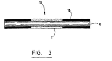
- the final result is a fiber that is completely or totally porous or a fiber having a porous cladding 11 and a solid core 13 such as the one illustrated on Fig. 3. If necessary, a slight layer of polymer 15 may be applied on the exterior of the fiber.
- the porous section 11 of the fiber has a length of approximately 2 cm.
- Porous glass has an index of refraction which is necessarily lower than that of solid glass and thus the guiding requirements are met.
- the pores absorb this gas and vapor and retain them. The more the pores are filled, the more the index of the porous glass increases. This change in index affects the guiding properties of the fiber and thus these guiding properties become an indication of the adsorption in the pores.
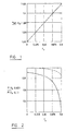
- Fig. 1 shows the effective index of refraction increase as a function of the volume of pores that is filled with a solvent where n eff is the effective refraction index of the fiber and f s is the function of porous volume occupied by the solvent.
- the behaviour of the fiber 10 is also a function of the geometrical form of the fiber 10: length and curvature of the fiber 10.
- multi-turn fibers 10 of small radius can thus be manufactured and are more sensitive than a straight fiber.
- Fig. 2 shows how the transmitted power varies as a function of the volume of pores that is filled with a solvent and how this varies as a function of the radius R of curvature of the fiber.
- the dotted line represents the power transmitted for a radius of curvature of 10 cm
- the solid line represents the power transmitted for a radius of curvature of 2 cm.
- Optical fiber indicators as described above can thus be used as end-of-service indicators for respiratory cartridges, where the end-of-service indicator comprises an optical fiber 10 having two opposite extremities 21, 23, one 21 of the extremities being connected to a light source 31, the other extremity 23 being connected to a detector 41 which measures the intensity of light transmitted by the fiber.
- An alarm 51 is operatively connected to the detector 41 and triggered when the intensity of light (or power) measured by the detector 41 is below a predetermined level.
- the optical fiber 10 is characterized in that at least a portion of the fiber 10 is porous.
- the end-of-service indicator 1' is placed inside a respirator cartridge 100 having a gas/vapor sorbent 101 so that when the respirator cartridge 100 is used in a toxic environment, the gas/vapor sorbent 101 gradually becomes saturated, thereby lowering the transmission properties of the optical fiber 10.
- the detector 41 and the light source 31 may be integrated to the fiber or to the electronic module 60.
- optical fibers operatively connect the sensing fiber 10 to the electronic module 60.
- Various approaches are possible to interface the fiber 10 and the electronic module 60 and which are simple and economical.
- the fiber 10 itself costs almost nothing when manufactured in great quantities and may be discarded after usage.
- the electronic module 10 measures the intensity of the light transmitted by the fiber.
- the pores of the cladding will fill up through adsorption. It is the same principle as for the activated carbon used in respiratory cartridges.
- the index of the cladding will increase as a function of the volume of pores that are saturated by the solvent. This increase of the index will finally affect the guiding properties of the fiber 10 and this effect is increasingly present when the curvature of the fiber is important. An increased curvature of the fiber diminishes the angle of incidence of the light beam and the guiding becomes more and more difficult. In practice, an important decrease of the light transmission is observed when the fibers are exposed to vapors of various solvents.
- the fiber 10 may be sandwiched between a disposable cartridge and a second cartridge which protects the indicator against excess humidity and which protects the user when the disposable cartridge fails.
- the transmission decreases under a pre-established threshold value and an audible or visual alarm is triggered.
- the indicator Since the principle of the indicator resides in the phenomenon of adsorption and guiding losses, the indicator is not selective and works with all products susceptible of being absorbed by activated carbon. In fact, the indicator reacts when the porous glass is saturated - which happens when the activated carbon saturates.
- the experimental equipment used to evaluate performances of the indicator are illustrated on Figure 9b.
- the extremities 21, 23 of the fiber are mounted in small aluminum blocks which have the necessary openings to receive the fiber 10 and the detector 41 or the light source 31. It is important to note that the extremities of the fibers are used as is, i.e. without polishing or special preparation. There is no precision adjustment and the fiber is easily installed in the blocks in a few seconds. This fiber remains nonetheless relatively fragile and brittle.
- the specifications of the fibers used for laboratory testing are the following:
- Fig. 9a is essentially an amplifier followed by a voltage-frequency converter, the latter controlling a LED.
- the detector 41 used is a phototransistor (Q1) and the light source is an electrolight diode (D2) in the infrared region (800nm). These elements were chosen because they represent which is the most common in the area of electro-optical components. They are very cheap as they are used within devices of mass consumption, i.e. infrared remote control.
- the electronic circuit allows to feed the light source and measures the power transmitted by the fiber.
- the electronic card also includes a circuit which triggers a blinking LED (D1). The frequency of the blinking increases when the transmission of the fiber decreases. This allows to have visual indication of the state of the fiber.
- the electronics are supplied by a 9-volt battery. It should however be understood that any means for evaluating the transmission properties of the fiber will meet the objectives of the invention.
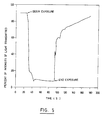
- Figure 4 illustrates a first result obtained with the indicator.
- This graph shows the power transmitted by the fiber 10 when the indicators exposed to a humid environment of 90% relative humidity.
- the indicator was placed in an environmental chamber with automatic control of the relative humidity.
- the oscillations of the signal at 90% relative humidity are caused by the system of the chamber which continually corrects the degree of humidity by very fine jets of water vapor.
- the signal recuperates, but very slowly. In this case, the desorption is a much slower process.
- the indicator 1 was placed in a hermetic box in the presence of an open container containing the solvent. The indicator 1 was thus exposed at concentrations that are relatively high equal to those pressures of vapor of the solvents used.
- Figure 5 illustrates the results with a fiber 10 in the presence of acetone. The response of the indicator 1 is very quick as can be seen from this Figure 5. The recuperating period is also relatively quick but demonstrates a behaviour that is much more complex but is reproducible, at least for the few tries that we have made.
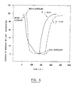
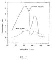
- Figure 6 illustrates the result in the presence of toluene.
- the solvent that is significant as the indicator reacts with all of those that we have tested (methanol, isopropanol, etc.).
- This graphic illustrates however the variation of response in function of the curvature of the fiber. With a radius of curvature of 2 cm, the indicator responds more rapidly than with a radius of curvature of 10 cm and is thus more sensitive.
Landscapes
- Health & Medical Sciences (AREA)
- Pulmonology (AREA)
- General Health & Medical Sciences (AREA)
- Business, Economics & Management (AREA)
- Emergency Management (AREA)
- Investigating Or Analysing Materials By The Use Of Chemical Reactions (AREA)
- Respiratory Apparatuses And Protective Means (AREA)
Claims (8)
- Combinaison d'un indicateur (1) de fin de service et d'une cartouche (100) respiratoire, ladite cartouche respiratoire ayant un sorbant (101) de gaz/vapeur,
ledit indicateur de fin de service comprenant des moyens de détection pour détecter un niveau de saturation dudit sorbant de gaz/vapeur entourant ledit indicateur et une alarme reliée fonctionnellement auxdits moyens de détection, ladite alarme étant déclenchée quand ledit sorbant de gaz/vapeur est saturé au-delà d'un niveau prédéterminé ;
caractérisée en ce que :lesdits moyens de détection comprennent une fibre optique (10) ayant deux extrémités opposées (21, 23), l'une (21) desdites extrémités étant reliée à une source lumineuse, l'autre (23) desdites extrémités étant reliée à un détecteur (41), ledit détecteur étant conçu pour mesurer l'intensité de la lumière transmise par ladite fibre (10), dans lequel au moins une portion de ladite fibre (10) est poreuse, les pores de ladite section poreuse étant ajustés de manière appropriée pour se remplir par adsorption quand le sorbant de gaz/vapeur est saturé ; ladite portion de ladite fibre (10) qui est poreuse adsorbe du gaz et de la vapeur quand le sorbant de gaz/vapeur est saturé, ce qui augmente ainsi l'indice de réfraction de la portion de la fibre qui est poreuse en fonction du volume de pores qui sont saturés par le gaz/vapeur, diminue les propriétés de transmission de la fibre, déclenchant ainsi l'alarme lorsque le sorbant de gaz/vapeur est saturé et que l'intensité de la lumière mesurée par le détecteur tombe au-dessous d'un niveau prédéterminé. - Combinaison selon la revendication 1, dans laquelle ladite fibre (10) a une gaine (11) et une âme (13), et ladite au moins une portion de ladite fibre optique (10) qui est poreuse est ladite gaine (11).
- Combinaison selon la revendication 1, dans laquelle ladite fibre (10) a une gaine (11) et une âme (13), et ladite au moins une portion de ladite fibre optique (10) qui est poreuse est ladite gaine (11) et ladite âme (13).
- Combinaison selon la revendication 2, dans laquelle ladite fibre optique (10) comprend en outre un revêtement (15) en polymère.
- Combinaison selon la revendication 1, dans laquelle ladite au moins une portion de ladite fibre optique (10) qui est poreuse a une longueur d'environ 2 cm.
- Combinaison selon l'une quelconque des revendications 1 à 5, dans laquelle ladite fibre optique (10) est rectiligne.
- Combinaison selon l'une quelconque des revendications 1, 2 ou 4, dans laquelle ladite au moins une portion de ladite fibre optique (10) est en tire-bouchon.
- Combinaison selon l'une quelconque des revendications 1 à 7, dans laquelle ladite source lumineuse est une diode électroluminescente (D2) ;
ledit détecteur comprend un capteur (Q1) de lumière ayant une sortie qui est reliée fonctionnellement à un amplificateur, ledit amplificateur étant relié fonctionnellement à un convertisseur tension-fréquence ; et
ladite alarme (51) est une diode électroluminescente (D1).
Applications Claiming Priority (3)
| Application Number | Priority Date | Filing Date | Title |
|---|---|---|---|
| CA2219854 | 1997-11-21 | ||
| CA002219854A CA2219854C (fr) | 1997-11-21 | 1997-11-21 | Indicateur d'arret de cartouches d'appareils respiratoires |
| PCT/CA1998/000820 WO1999027352A1 (fr) | 1997-11-21 | 1998-08-27 | Indicateur de fin de service d'une cartouche respiratoire |
Publications (2)
| Publication Number | Publication Date |
|---|---|
| EP1032823A1 EP1032823A1 (fr) | 2000-09-06 |
| EP1032823B1 true EP1032823B1 (fr) | 2003-05-07 |
Family
ID=4161711
Family Applications (1)
| Application Number | Title | Priority Date | Filing Date |
|---|---|---|---|
| EP98941181A Expired - Lifetime EP1032823B1 (fr) | 1997-11-21 | 1998-08-27 | Indicateur de fin de service d'une cartouche respiratoire |
Country Status (6)
| Country | Link |
|---|---|
| EP (1) | EP1032823B1 (fr) |
| JP (1) | JP2002506662A (fr) |
| AU (1) | AU8968298A (fr) |
| CA (1) | CA2219854C (fr) |
| DE (1) | DE69814447D1 (fr) |
| WO (1) | WO1999027352A1 (fr) |
Families Citing this family (5)
| Publication number | Priority date | Publication date | Assignee | Title |
|---|---|---|---|---|
| US8459200B2 (en) | 2008-06-30 | 2013-06-11 | 3M Innovative Properties Company | Exposure indicating device |
| US8821621B2 (en) | 2010-04-02 | 2014-09-02 | 3M Innovative Properties Company | Filter systems including optical analyte sensors and optical readers |
| US9192795B2 (en) | 2011-10-07 | 2015-11-24 | Honeywell International Inc. | System and method of calibration in a powered air purifying respirator |
| US9808656B2 (en) | 2012-01-09 | 2017-11-07 | Honeywell International Inc. | System and method of oxygen deficiency warning in a powered air purifying respirator |
| WO2018106258A1 (fr) * | 2016-12-09 | 2018-06-14 | Honeywell International Inc. | Indicateur de fin de durée de vie pour masque facial jetable |
Family Cites Families (4)
| Publication number | Priority date | Publication date | Assignee | Title |
|---|---|---|---|---|
| US4146887A (en) * | 1977-08-05 | 1979-03-27 | American Optical Corporation | Respirator cartridge end-of-service life indicator |
| EP0061884A1 (fr) * | 1981-03-30 | 1982-10-06 | Imperial Chemical Industries Plc | Capteur en fibre optique |
| US4846548A (en) * | 1987-05-06 | 1989-07-11 | St&E, Inc. | Fiber optic which is an inherent chemical sensor |
| US5250095A (en) * | 1988-08-16 | 1993-10-05 | Rutgers University | Method for making porous glass optical fiber sensor |
-
1997
- 1997-11-21 CA CA002219854A patent/CA2219854C/fr not_active Expired - Lifetime
-
1998
- 1998-08-27 JP JP2000522441A patent/JP2002506662A/ja not_active Withdrawn
- 1998-08-27 DE DE69814447T patent/DE69814447D1/de not_active Expired - Lifetime
- 1998-08-27 WO PCT/CA1998/000820 patent/WO1999027352A1/fr not_active Ceased
- 1998-08-27 AU AU89682/98A patent/AU8968298A/en not_active Abandoned
- 1998-08-27 EP EP98941181A patent/EP1032823B1/fr not_active Expired - Lifetime
Also Published As
| Publication number | Publication date |
|---|---|
| AU8968298A (en) | 1999-06-15 |
| WO1999027352A1 (fr) | 1999-06-03 |
| CA2219854C (fr) | 2005-09-20 |
| JP2002506662A (ja) | 2002-03-05 |
| CA2219854A1 (fr) | 1999-05-21 |
| DE69814447D1 (de) | 2003-06-12 |
| EP1032823A1 (fr) | 2000-09-06 |
Similar Documents
| Publication | Publication Date | Title |
|---|---|---|
| US6375725B1 (en) | End-of-service indicator including porous waveguide for respirator cartridge | |
| US20040189982A1 (en) | Optical sensor for volatile organic compounds | |
| US5315673A (en) | Optical waveguide vapor sensor | |
| US5995686A (en) | Fiber-optic sensor device and method | |
| US6061141A (en) | Method and system for detecting gases or vapors in a monitored area | |
| US7842243B2 (en) | Chemical sensor with an indicator dye | |
| US20130263640A1 (en) | Method for correlating a monitoring device to the end of service life of a filter cartridge | |
| US5567622A (en) | Sensor for detection of nitrogen dioxide and nitrogen tetroxide | |
| JP6045496B2 (ja) | 耐用期間終点表示用の可搬型モニター | |
| RU2490615C2 (ru) | Многослойные матрицы колориметрических датчиков | |
| AU2007297046A1 (en) | Organic vapor sorbent protective device with thin film indicator | |
| King et al. | Optical‐Fiber‐Mounted Porous Silicon Photonic Crystals for Sensing Organic Vapor Breakthrough in Activated Carbon | |
| WO2004057314A2 (fr) | Procede et capteur permettant de detecter une substance chimique au moyen d'un materiau presentant une anisotropie optique | |
| CA2932473A1 (fr) | Capteur de gaz | |
| EP1032823B1 (fr) | Indicateur de fin de service d'une cartouche respiratoire | |
| Mac Craith et al. | Fibre optic chemical sensors based on evanescent wave interactions in sol-gel-derived porous coatings: Code: F7 | |
| US7894069B2 (en) | Respirator end-of-service life probe | |
| CA2628699A1 (fr) | Sonde de fin de duree de vie pour appareil respiratoire | |
| JP2021508063A (ja) | ナノ多孔性材料を含むセンサ及びそのセンサを使用して検体を検出するための方法 | |
| Hypszer et al. | Fiber optic technique for relative humidity sensors | |
| US6605804B1 (en) | Optical sensor | |
| FR2895518A1 (fr) | Procede de mesure et d'alertes fiabilisees et individualisees de pollutions de l'air et dispositif associe | |
| Ghazaly et al. | Real-time optical ozone sensor for occupational exposure assessment | |
| Suzuki et al. | Hetero-core fiber SPR sensor with ionic liquid gel coating for CO 2 detection | |
| Caron et al. | Porous glass optical fiber sensor as an end-of-service indicator for respiratory cartridges |
Legal Events
| Date | Code | Title | Description |
|---|---|---|---|
| PUAI | Public reference made under article 153(3) epc to a published international application that has entered the european phase |
Free format text: ORIGINAL CODE: 0009012 |
|
| 17P | Request for examination filed |
Effective date: 20000620 |
|
| AK | Designated contracting states |
Kind code of ref document: A1 Designated state(s): DE FR GB IT |
|
| 17Q | First examination report despatched |
Effective date: 20010525 |
|
| GRAH | Despatch of communication of intention to grant a patent |
Free format text: ORIGINAL CODE: EPIDOS IGRA |
|
| GRAH | Despatch of communication of intention to grant a patent |
Free format text: ORIGINAL CODE: EPIDOS IGRA |
|
| GRAA | (expected) grant |
Free format text: ORIGINAL CODE: 0009210 |
|
| AK | Designated contracting states |
Designated state(s): DE FR GB IT |
|
| PG25 | Lapsed in a contracting state [announced via postgrant information from national office to epo] |
Ref country code: IT Free format text: LAPSE BECAUSE OF FAILURE TO SUBMIT A TRANSLATION OF THE DESCRIPTION OR TO PAY THE FEE WITHIN THE PRESCRIBED TIME-LIMIT;WARNING: LAPSES OF ITALIAN PATENTS WITH EFFECTIVE DATE BEFORE 2007 MAY HAVE OCCURRED AT ANY TIME BEFORE 2007. THE CORRECT EFFECTIVE DATE MAY BE DIFFERENT FROM THE ONE RECORDED. Effective date: 20030507 Ref country code: FR Free format text: LAPSE BECAUSE OF FAILURE TO SUBMIT A TRANSLATION OF THE DESCRIPTION OR TO PAY THE FEE WITHIN THE PRESCRIBED TIME-LIMIT Effective date: 20030507 |
|
| REG | Reference to a national code |
Ref country code: GB Ref legal event code: FG4D |
|
| REF | Corresponds to: |
Ref document number: 69814447 Country of ref document: DE Date of ref document: 20030612 Kind code of ref document: P |
|
| PG25 | Lapsed in a contracting state [announced via postgrant information from national office to epo] |
Ref country code: DE Free format text: LAPSE BECAUSE OF FAILURE TO SUBMIT A TRANSLATION OF THE DESCRIPTION OR TO PAY THE FEE WITHIN THE PRESCRIBED TIME-LIMIT Effective date: 20030808 |
|
| PLBE | No opposition filed within time limit |
Free format text: ORIGINAL CODE: 0009261 |
|
| STAA | Information on the status of an ep patent application or granted ep patent |
Free format text: STATUS: NO OPPOSITION FILED WITHIN TIME LIMIT |
|
| 26N | No opposition filed |
Effective date: 20040210 |
|
| EN | Fr: translation not filed | ||
| PGFP | Annual fee paid to national office [announced via postgrant information from national office to epo] |
Ref country code: GB Payment date: 20170719 Year of fee payment: 20 |
|
| REG | Reference to a national code |
Ref country code: GB Ref legal event code: PE20 Expiry date: 20180826 |
|
| PG25 | Lapsed in a contracting state [announced via postgrant information from national office to epo] |
Ref country code: GB Free format text: LAPSE BECAUSE OF EXPIRATION OF PROTECTION Effective date: 20180826 |