EP1032961B1 - Antennenanlage und verfahren zum betreiben einer antennenanlage - Google Patents
Antennenanlage und verfahren zum betreiben einer antennenanlage Download PDFInfo
- Publication number
- EP1032961B1 EP1032961B1 EP98954650A EP98954650A EP1032961B1 EP 1032961 B1 EP1032961 B1 EP 1032961B1 EP 98954650 A EP98954650 A EP 98954650A EP 98954650 A EP98954650 A EP 98954650A EP 1032961 B1 EP1032961 B1 EP 1032961B1
- Authority
- EP
- European Patent Office
- Prior art keywords
- antenna
- reception
- minimum
- received
- auxiliary antenna
- Prior art date
- Legal status (The legal status is an assumption and is not a legal conclusion. Google has not performed a legal analysis and makes no representation as to the accuracy of the status listed.)
- Expired - Lifetime
Links
- 238000000034 method Methods 0.000 title claims description 5
- 230000000694 effects Effects 0.000 claims abstract 3
- 230000001105 regulatory effect Effects 0.000 claims 1
- 230000001629 suppression Effects 0.000 abstract description 4
- 238000009434 installation Methods 0.000 abstract 1
- 238000013016 damping Methods 0.000 description 5
- 238000001514 detection method Methods 0.000 description 5
- 239000007787 solid Substances 0.000 description 4
- 230000007257 malfunction Effects 0.000 description 2
- 230000003044 adaptive effect Effects 0.000 description 1
- 230000002238 attenuated effect Effects 0.000 description 1
- 238000010586 diagram Methods 0.000 description 1
- 239000005433 ionosphere Substances 0.000 description 1
- 230000010363 phase shift Effects 0.000 description 1
- 230000003449 preventive effect Effects 0.000 description 1
- 239000005436 troposphere Substances 0.000 description 1
Images
Classifications
-
- H—ELECTRICITY
- H01—ELECTRIC ELEMENTS
- H01Q—ANTENNAS, i.e. RADIO AERIALS
- H01Q3/00—Arrangements for changing or varying the orientation or the shape of the directional pattern of the waves radiated from an antenna or antenna system
- H01Q3/26—Arrangements for changing or varying the orientation or the shape of the directional pattern of the waves radiated from an antenna or antenna system varying the relative phase or relative amplitude of energisation between two or more active radiating elements; varying the distribution of energy across a radiating aperture
- H01Q3/2605—Array of radiating elements provided with a feedback control over the element weights, e.g. adaptive arrays
- H01Q3/2611—Means for null steering; Adaptive interference nulling
- H01Q3/2629—Combination of a main antenna unit with an auxiliary antenna unit
-
- G—PHYSICS
- G01—MEASURING; TESTING
- G01S—RADIO DIRECTION-FINDING; RADIO NAVIGATION; DETERMINING DISTANCE OR VELOCITY BY USE OF RADIO WAVES; LOCATING OR PRESENCE-DETECTING BY USE OF THE REFLECTION OR RERADIATION OF RADIO WAVES; ANALOGOUS ARRANGEMENTS USING OTHER WAVES
- G01S19/00—Satellite radio beacon positioning systems; Determining position, velocity or attitude using signals transmitted by such systems
- G01S19/01—Satellite radio beacon positioning systems transmitting time-stamped messages, e.g. GPS [Global Positioning System], GLONASS [Global Orbiting Navigation Satellite System] or GALILEO
- G01S19/13—Receivers
- G01S19/21—Interference related issues ; Issues related to cross-correlation, spoofing or other methods of denial of service
-
- G—PHYSICS
- G01—MEASURING; TESTING
- G01S—RADIO DIRECTION-FINDING; RADIO NAVIGATION; DETERMINING DISTANCE OR VELOCITY BY USE OF RADIO WAVES; LOCATING OR PRESENCE-DETECTING BY USE OF THE REFLECTION OR RERADIATION OF RADIO WAVES; ANALOGOUS ARRANGEMENTS USING OTHER WAVES
- G01S7/00—Details of systems according to groups G01S13/00, G01S15/00, G01S17/00
- G01S7/02—Details of systems according to groups G01S13/00, G01S15/00, G01S17/00 of systems according to group G01S13/00
- G01S7/28—Details of pulse systems
- G01S7/2813—Means providing a modification of the radiation pattern for cancelling noise, clutter or interfering signals, e.g. side lobe suppression, side lobe blanking, null-steering arrays
-
- H—ELECTRICITY
- H01—ELECTRIC ELEMENTS
- H01Q—ANTENNAS, i.e. RADIO AERIALS
- H01Q21/00—Antenna arrays or systems
- H01Q21/29—Combinations of different interacting antenna units for giving a desired directional characteristic
Definitions
- the invention relates to an antenna system with a Omnidirectional antenna and with a (first) auxiliary antenna, the Receiving signals in terms of amplitude and phase can be combined in a desired direction of the room there is a minimum reception.
- the reception minimum serves
- the signals of an interferer (jammer) who is receiving the antenna system disturbs to dampen sufficiently strong, so that Useful signals from other directions than that of the interferer can be received.
- Such an antenna system with a broadcast antenna and two Auxiliary antennas, their received signals in terms of amplitude and phase can be combined that in a desired direction of the room Receiving minimum consists of HIRATA K ET AL: "A METHOD FOR ARRANGEMENT OF AUXILIARY ANTENNAS TO MINIMIZE THE INFLUENCE OF THE INCIDENT DIRECTIONS OF INTERFERENCES ON SUPPRESSION PERFORMANCE IN A MULTIPLE SIDELOBE CANCELLER "ELECTRONICS & COMMUNICATIONS IN JAPAN, PART I - COMMUNICATIONS, Vol. 80, No. 1, January 1997, pages 110-111, XP000687331.
- Omnidirectional antennas are well suited for reception of signals from satellites, particularly those relating to orbiting satellites are transmitted.
- satellites particularly those relating to orbiting satellites are transmitted.
- GPS Global Positioning System
- GPS receivers tolerate interference power up to one certain dimension are greater than the GPS reception power. In to large interference power is nevertheless a reduction in Interference power required.
- the invention has for its object a possibility to create the solid angle range with strong Attenuation of the received signal in the vicinity of the interferer, more generally the area around the spatial direction, in which a reception minimum is to be generated compared to known antenna system is reduced. This task will by the features of claim 1 and by the features of independent claim 7 solved.
- the arrangement can be such that that the former auxiliary antenna in cooperation with the Main antenna only generates a single reception minimum during operation or multiple reception minima generated.
- the other too Auxiliary antenna can only work in conjunction with the main antenna generate a single reception minimum or multiple reception minima. It is preferred that one of the auxiliary antennas (in the example the first-mentioned auxiliary antenna), only a single reception minimum generated, and that the other auxiliary antenna one Generated a plurality of reception minima.
- both the damping by the first-mentioned auxiliary antenna is achieved alone (if necessary through cooperation with the broadcast antenna) and the Attenuation achieved by the additional auxiliary antenna alone (if necessary again in cooperation with the Round antenna) dimensioned so that also in the area of Minimum reception of the first-mentioned auxiliary antenna or all Reception minima of the further auxiliary antenna the reception of the desired user signals, e.g. from satellites, in particular Location satellites, is still reliably possible.
- An advantage of the invention is that it is available of satellite signals compared to the prior art is enlarged, so that the invention in particular for safety-relevant systems, for example for permanent Aircraft approaching an airport accurate position signals is suitable.
- the former auxiliary antenna and / or the other Auxiliary antenna can also be a omnidirectional antenna, in particular with a hemispherical reception area.
- the advantage lies in the fact that electrical measures alone (Change of gain or damping, setting one suitable phase shift between the signals of the Auxiliary antennas and the omnidirectional antenna) the direction of the combined reception minimums in a wide solid angle range can be adjusted. But it may in certain Applications may also be possible as auxiliary antennas use that already have a certain directionality, especially when the interferer is immobile, so that a mechanical tracking of the antenna is not required. Such However, antennas are designed to attenuate interference signals other directions may be less suitable. There a Interferers that are generally close to the horizon are as Auxiliary antennas useful such broadcast antennas that in the Have a minimum reception in the direction vertically upwards.
- GNSS Global Navigation Satellite System
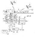
- a ground station 1 is practical in the example simultaneous reception of a plurality of GPS satellites 2 trained who emit time signals in a known manner, where at the location of the receiving station Arrival of the signals and those impressed on the satellite signals Time the runtime of the signals and thus the Distance of the respective satellite from the location of the ground station can be determined.
- the ground station 1 has a main antenna M, a first one Auxiliary antenna A1 and a second auxiliary antenna A2. All Antennas are those with an almost hemispherical Reception characteristics, i.e. they take signals out practically in all directions above ground Hemisphere. As a result, they are also able to receive the signals to be received by satellites very close to the horizon.
- the first auxiliary antenna A1 has M from the main antenna a distance d1 that is smaller than a wavelength of radio frequency radiated from the satellite. Appropriately this distance, for example, about 0.5 to 0.6 wavelengths. in the Example is d1 half a wavelength. Through this relative a small reception minimum is generated.
- the second auxiliary antenna A2 is at a distance from the main antenna M. d2, which is much larger than dl.
- d2 is 1 to 2 Wavelengths.
- d2 about 1.5 wavelengths.
- the distance between the two Auxiliary antennas is d and is as large as d1 in the example but also have other values.
- the output lines of each of the antennas carry signals EM (for the main antenna M), E1 (for the auxiliary antenna A1) and E2 (for the auxiliary antenna A2).
- the output lines of the three Antennas are each via a bandpass (BP) 5, through which signals outside the frequency range of interest can be suppressed, a low noise amplifier (LNA) 7 fed.
- the output lines of the low noise amplifier 7 are designated by the reference numerals 8 to 10.
- In the Output lines 9 and 10 of the two auxiliary antennas A1 and A2 is a digitally controllable, changing the amplitude (namely enlarging or reducing) electronic Gain / attenuator 11 and a phase changing digitally controllable phase element 12 switched.
- Attenuator 13 In the output line 8 of the main antenna M can, if necessary Attenuator 13 be turned on.
- the in amplitude and Phase and possibly by the attenuator 13th changed signals on lines 8 to 10 are one Summing element 15 supplied.
- a divider 16 carries part of the combined signal, possibly via a low-noise Amplifier 17, a GPS receiver 19 and others electronic devices of the ground station 1 for generation of the above correction signals.
- the first auxiliary antenna A1 together with the Main antenna M is able to change the amplitude and Phase on the output line 9 of the first auxiliary antenna only reception minimum in any direction of the room to create.
- the second auxiliary antenna A2 can because of its greater distance from the main antenna M together with this generate a plurality of reception minima such that one of these in a desired direction of the room where there is a Interferer shows.
- Another part of the combined signal is from the Divider 16 also via a low noise amplifier 22 and a detection unit 23 is fed to a processor 25 which is controlled by a program so that it is via control lines 26, 27, 28 and 29 the controllable gain / attenuation members 11 and phase elements 12 of the two auxiliary antennas adjusted so that a at the output of the detection unit 23 Signal minimum appears.
- a minimum in the total signal of the three antennas means that the signal of an interferer that is used to increase the overall signal has been largely eliminated.
- the only reception minimum of the first auxiliary antenna A1 shows when a minimum at the output of the detection unit is determined exactly in the direction of the interferer (it will assumed that it is only one interferer).
- One of the Receiving minima of the second auxiliary antenna A2 shows at reached minimum in that supplied to the detection unit 23 Signal also on the interferer. From everyone else Spatial areas can partially completely undamped satellite signals or in the area of the others (not on the interferer showing) minima of the second auxiliary antenna somewhat damped are received, this attenuation is nowhere as great is that the reception of the respective satellite is impeded.
- the minima of the additional auxiliary antenna are therefore because the distance d2 is larger than a wavelength in comparison to the only minimum of the former auxiliary antenna narrower and more pointed.
- means processor 25 executes an adaptive algorithm, who, even if the position of the interferer is not known beforehand, the exact setting of the antennas causes the influence of the interferer is reduced to a maximum.
- the attenuation only by the first auxiliary antenna is for example a maximum of 10 dB.
- the combination of the two on Minima aimed at the interferer leads to a very deep and narrow minimum. In contrast, arise in the other minimum angle ranges tolerable (i.e. not satellite reception preventive) narrow minima.
- the ground station of a GPS system described.
- the above statements are also based on other systems using satellites are applicable.
- the ground station according to the invention and the invention Method for operating the ground station for satellite-based Navigation or landing systems is supported by the proposed measures significantly improved. It can be immediate an alarm criterion can be derived in the event of a fault. In the event of a malfunction, the control signals for the attenuator and phase link of the first auxiliary antenna Direction of the interferer.
- Embodiment produces both the former auxiliary antenna as well as the additional auxiliary antenna only one at a time Reception minimum, to suppress one interferer be adjusted to this.
- the Auxiliary antennas about the same distance from the omnidirectional antenna (Main antenna) can be arranged away.
- the total effective reception minimum not quite as narrow and pointed as in the example described above.
- Each auxiliary antenna has a single minimum on the interferer aligned. The overall effective minimum can be found here advantageously extremely narrow and pointed. Indeed is required when setting up and / or operating the system special care to prevent that in Spatial directions in which there is no interferer, minima of the two auxiliary antennas and thereby the reception of Prevent satellite signals.
- the invention relates to an antenna system with a Round receiving antenna M and with an auxiliary antenna A1, the Receiving signals in terms of amplitude and phase can be combined in a desired direction of the room there is a minimum reception. It is another auxiliary antenna A2 arranged and connectable such that at least one Reception minimum arises, with exactly one reception minimum in shows the desired direction of the room and with the mentioned by the first-mentioned auxiliary antenna Receiving minimum corresponds in its direction, and the attenuations on that of the first-mentioned auxiliary antenna generated reception minimum and at least one of the further auxiliary antenna generated reception minimum so dimensioned are that they each receive one with one do not impede the predetermined minimum level of the transmitter, and that the receiving minima coinciding in their direction together cause greater damping, such that they are used for Suppress interference.
Landscapes
- Engineering & Computer Science (AREA)
- Radar, Positioning & Navigation (AREA)
- Remote Sensing (AREA)
- Computer Networks & Wireless Communication (AREA)
- Physics & Mathematics (AREA)
- General Physics & Mathematics (AREA)
- Variable-Direction Aerials And Aerial Arrays (AREA)
- Position Fixing By Use Of Radio Waves (AREA)
- Input Circuits Of Receivers And Coupling Of Receivers And Audio Equipment (AREA)
- Radar Systems Or Details Thereof (AREA)
Description
Claims (9)
- Antennenanlage mit einer Rundempfangsantenne (Hauptantenne M) und mit einer (ersten) Hilfsantenne (A1), deren Empfangssignale bezüglich Amplitude und Phase derart kombinierbar sind, daß in einer gewünschten Richtung des Raums ein Empfangsminimum besteht, und mit einer weiteren Hilfsantenne (A2) derart angeordnet und koppelbar, daß mindestens ein Empfangsminimum entsteht, dadurch gekennzeichnet, daß genau ein Empfangsminimum in die genannte gewünschte Richtung des Raums zeigt und mit dem von der erstgenannten Hilfsantenne (A1) zusammen mit der Hauptantenne (M) erzeugten genannten Empfangsminimum bezüglich seiner Richtung übereinstimmt, und wobei die Dämpfungen an dem von der erstgenannten Hilfsantenne erzeugten Empfangsminimum und an dem mindestens einen von der weiteren Hilfsantenne erzeugten Empfangsminimum so bemessen sind, daß sie je für sich allein den Empfang eines mit einem vorbestimmten Mindestpegel sendenden Senders nicht behindern, und daß die in ihrer Richtung übereinstimmenden Empfangsminima gemeinsam eine größere Dämpfung bewirken, derart, daß sie zum Unterdrücken von Störern geeignet sind.
- Antennenanlage nach Anspruch 1, dadurch gekennzeichnet, daß die erstgenannte Hilfsantenne (A1) zusammen mit der Hauptantenne (M) genau ein Empfangsminimum erzeugt, und daß die weitere Hilfsantenne (A2) zusammen mit der Hauptantenne (M) eine Mehrzahl von Empfangsminima in unterschiedlichen Richtungen erzeugt.
- Antennenanlage nach Anspruch 1 oder 2, dadurch gekennzeichnet, daß die weitere Hilfsantenne (A2) von der Rundempfangsantenne (M) weiter entfernt ist als die erstgenannte Hilfsantenne (A1).
- Antennenanlage nach einem der vorhergehenden Ansprüche, dadurch gekennzeichnet, daß zum Unterdrücken von mehreren Störern mehrere erste und mehrere weitere Hilfsantennen vorgesehen sind.
- Antennenanlage nach einem der vorhergehenden Ansprüche, dadurch gekennzeichnet, daß mindestens eine der genannten Hilfsantennen eine Rundempfangscharakteristik hat.
- Antennenanlage nach einem der vorhergehenden Ansprüche, dadurch gekennzeichnet, daß eine Regelungsanordnung zum automatischen Unterdrücken eines Störers vorgesehen ist.
- Antennenanlage nach einem der vorhergehenden Ansprüche, dadurch gekennzeichnet, daß der Abstand (d1) der erstgenannten Hilfsantenne (A1) von der Hauptantenne (M) kleiner ist als eine Wellenlänge.
- Antennenanlage nach einem der vorhergehenden Ansprüche, dadurch gekennzeichnet, daß der Abstand (d2) der zweiten Hilfsantenne (A2) von der Hauptantenne (M) mindestens eine Wellenlänge beträgt.
- Verfahren zum Betreiben einer Antennenanlage mit einer Rundempfangsantenne (Hauptantenne M) und mit einer Hilfsantenne (A1), deren Empfangssignale bezüglich Amplitude und Phase derart kombinierbar sind, daß in einer gewünschten Richtung des Raums ein Empfangsminimum besteht, und mit einer weiteren Hilfsantenne (A2), die derart angeordnet und koppelbar ist, daß eine Mehrzahl von Empfangsminima entsteht, dadurch gekennzeichnet, daß die Amplituden und Phasen der Empfangssignale der Hilfsantennen (A1, A2) derart eingestellt werden, daß ein von der weiteren Hilfsantenne (A2) erzeugtes Empfangsminimum in die genannte gewünschte Richtung des Raums zeigt und mit dem von der erstgenannten Hilfsantenne (A1) erzeugten genannten Empfangsminimum bezüglich seiner Richtung übereinstimmt, und wobei die Dämpfungen an dem von der erstgenannten Hilfsantenne (A1) erzeugten Empfangsminimum und an den von der weiteren Hilfsantenne (A2) erzeugten Empfangsminima so bemessen werden, daß sie je für sich allein den Empfang eines mit einem vorbestimmten Mindestpegel sendenden Senders nicht behindern, und daß die in ihrer Richtung übereinstimmenden Empfangsminima gemeinsam eine größere Dämpfung bewirken, derart, daß sie zum Unterdrücken von Störern geeignet sind.
Applications Claiming Priority (3)
| Application Number | Priority Date | Filing Date | Title |
|---|---|---|---|
| DE19751122 | 1997-11-19 | ||
| DE19751122A DE19751122A1 (de) | 1997-11-19 | 1997-11-19 | Antennenanlage und Verfahren zum Betreiben einer Antennenanlage |
| PCT/IB1998/001831 WO1999026313A1 (de) | 1997-11-19 | 1998-11-19 | Antennenanlage und verfahren zum betreiben einer antennenanlage |
Publications (2)
| Publication Number | Publication Date |
|---|---|
| EP1032961A1 EP1032961A1 (de) | 2000-09-06 |
| EP1032961B1 true EP1032961B1 (de) | 2003-09-03 |
Family
ID=7849113
Family Applications (1)
| Application Number | Title | Priority Date | Filing Date |
|---|---|---|---|
| EP98954650A Expired - Lifetime EP1032961B1 (de) | 1997-11-19 | 1998-11-19 | Antennenanlage und verfahren zum betreiben einer antennenanlage |
Country Status (8)
| Country | Link |
|---|---|
| US (1) | US6323806B1 (de) |
| EP (1) | EP1032961B1 (de) |
| JP (1) | JP2001523906A (de) |
| AT (1) | ATE249105T1 (de) |
| CA (1) | CA2310387A1 (de) |
| DE (2) | DE19751122A1 (de) |
| ES (1) | ES2207005T3 (de) |
| WO (1) | WO1999026313A1 (de) |
Families Citing this family (15)
| Publication number | Priority date | Publication date | Assignee | Title |
|---|---|---|---|---|
| US7181171B2 (en) * | 2001-07-20 | 2007-02-20 | Kyocera Wireless Corp. | System and method for providing auxiliary reception in a wireless communications system |
| US8193978B2 (en) * | 2007-11-14 | 2012-06-05 | Golba Llc | Positioning system and method using GPS with wireless access points |
| US8838481B2 (en) | 2011-07-26 | 2014-09-16 | Golba Llc | Method and system for location based hands-free payment |
| US8838477B2 (en) | 2011-06-09 | 2014-09-16 | Golba Llc | Method and system for communicating location of a mobile device for hands-free payment |
| US20110080320A1 (en) * | 2009-10-02 | 2011-04-07 | etherwhere Corporation | Signal processing techniques for improving the sensitivity of GPS receivers |
| US20110080321A1 (en) * | 2009-10-02 | 2011-04-07 | etherwhere Corporation | Signal processing techniques for improving the sensitivity of GPS receivers |
| US11344285B2 (en) | 2009-12-16 | 2022-05-31 | Boston Scientific Scimed, Inc. | Multi-lumen-catheter retractor system for a minimally-invasive, operative gastrointestinal treatment |
| US9806790B2 (en) | 2010-03-29 | 2017-10-31 | Odyssey Wireless, Inc. | Systems/methods of spectrally efficient communications |
| US9042857B2 (en) | 2010-08-30 | 2015-05-26 | Physical Devices, Llc | Methods, systems, and non-transitory computer readable media for wideband frequency and bandwidth tunable filtering |
| US8666347B2 (en) | 2010-10-14 | 2014-03-04 | Physical Devices, Llc | Methods and devices for reducing radio frequency interference |
| US9350401B2 (en) | 2010-08-30 | 2016-05-24 | Physical Devices, Llc | Tunable filter devices and methods |
| EP2820447A4 (de) * | 2012-02-28 | 2015-11-11 | Physical Devices Llc | Verfahren, systeme und computerlesbare medien zur abschwächung bandinterner interferenzen von gps-signalen |
| US8718587B2 (en) * | 2012-04-18 | 2014-05-06 | Qualcomm Incorporated | Reconfigurable LNA for increased jammer rejection |
| US20150244431A1 (en) | 2014-02-21 | 2015-08-27 | Physical Devices, Llc | Devices and methods for diversity signal enhancement and cosite cancellation |
| DE102014210204A1 (de) * | 2014-05-28 | 2015-12-03 | Lufthansa Systems Gmbh & Co. Kg | Vorrichtung und Verfahren zur Luft-Boden-Kommunikation von Luftfahrzeugen |
Family Cites Families (9)
| Publication number | Priority date | Publication date | Assignee | Title |
|---|---|---|---|---|
| US3922685A (en) * | 1973-07-30 | 1975-11-25 | Motorola Inc | Antenna pattern generator and switching apparatus |
| US4225870A (en) * | 1978-05-10 | 1980-09-30 | The United States Of America As Represented By The Secretary Of The Army | Null steering antenna |
| US4313116A (en) * | 1980-01-30 | 1982-01-26 | Westinghouse Electric Corp. | Hybrid adaptive sidelobe canceling system |
| DE3006627A1 (de) * | 1980-02-22 | 1981-08-27 | Robert Bosch Gmbh, 7000 Stuttgart | Verfahren zum stoerungsfreien empfangen von ukw-signalen in fahrzeugen |
| US4280128A (en) * | 1980-03-24 | 1981-07-21 | The United States Of America As Represented By The Secretary Of The Army | Adaptive steerable null antenna processor |
| DE3314387A1 (de) * | 1983-04-21 | 1984-10-31 | Rohde & Schwarz GmbH & Co KG, 8000 München | Rundempfangsantenne |
| USH740H (en) * | 1989-06-13 | 1990-02-06 | The United States Of America As Represented By The Secretary Of The Army | Antenna sidelobe interference canceller |
| JPH0748665B2 (ja) * | 1992-12-14 | 1995-05-24 | 日本電気株式会社 | サイドローブキャンセラ |
| JP2561028B2 (ja) * | 1994-05-26 | 1996-12-04 | 日本電気株式会社 | サイドローブキャンセラ |
-
1997
- 1997-11-19 DE DE19751122A patent/DE19751122A1/de not_active Withdrawn
-
1998
- 1998-11-19 JP JP2000521566A patent/JP2001523906A/ja not_active Withdrawn
- 1998-11-19 CA CA002310387A patent/CA2310387A1/en not_active Abandoned
- 1998-11-19 DE DE59809510T patent/DE59809510D1/de not_active Expired - Lifetime
- 1998-11-19 WO PCT/IB1998/001831 patent/WO1999026313A1/de not_active Ceased
- 1998-11-19 AT AT98954650T patent/ATE249105T1/de not_active IP Right Cessation
- 1998-11-19 ES ES98954650T patent/ES2207005T3/es not_active Expired - Lifetime
- 1998-11-19 US US09/530,971 patent/US6323806B1/en not_active Expired - Fee Related
- 1998-11-19 EP EP98954650A patent/EP1032961B1/de not_active Expired - Lifetime
Also Published As
| Publication number | Publication date |
|---|---|
| CA2310387A1 (en) | 1999-05-27 |
| DE19751122A1 (de) | 1999-05-20 |
| EP1032961A1 (de) | 2000-09-06 |
| JP2001523906A (ja) | 2001-11-27 |
| US6323806B1 (en) | 2001-11-27 |
| WO1999026313A1 (de) | 1999-05-27 |
| ES2207005T3 (es) | 2004-05-16 |
| ATE249105T1 (de) | 2003-09-15 |
| DE59809510D1 (de) | 2003-10-09 |
Similar Documents
| Publication | Publication Date | Title |
|---|---|---|
| DE3881557T2 (de) | Landehilfssystem unter verwendung von navigationssatelliten. | |
| DE69626250T2 (de) | Verfahren und Vorrichtung zur elektronischen Polarisationskorrektur | |
| DE19751122A1 (de) | Antennenanlage und Verfahren zum Betreiben einer Antennenanlage | |
| EP3688494B1 (de) | Verfahren und vorrichtung zum bereitstellen von korrekturdaten zur satellitennavigation | |
| DE60320592T2 (de) | Erhöhung der leistung eines empfängers unter dem einfluss von interferenzen | |
| DE102008059424A1 (de) | Sekundärradarsystem mit dynamischer Sektorisierung des zu überwachenden Raumes unter Verwendung von Multi-Antennenanordnungen und Verfahren hierzu | |
| DE102010019081A9 (de) | Breitband-Antennensystem zur Satellitenkommunikation | |
| DE102015005465A1 (de) | Vorrichtung und Verfahren zum Erzeugen und Bereitstellen von Positionsinformationen | |
| EP2000819A1 (de) | Antennenkombination für eine mobile GNSS-Station und mobile GNSS-Station | |
| DE10209060B4 (de) | Empfangsantennenanordnung für Satelliten- und/oder terrestrische Funksignale auf Fahrzeugen | |
| DE102022101576A1 (de) | Verfahren zur Reduktion von Auswirkungen einer Störunterdrückung auf die Messung einer Phasenverschiebung eines Satellitennavigationssignals am Ort seines Empfangs sowie Anwendungen dieses Verfahrens | |
| EP2078965B1 (de) | Überwachungseinrichtung für ein augmentiertes satellitenbasiertes Positionsbestimmungssystem und augmentiertes satellitenbasiertes Positionsbestimmungssystem | |
| DE102021128221A1 (de) | Antennensystem für den Empfang von Signalen von einer Sendeantenne | |
| EP2367026B1 (de) | Vorrichtung und Verfahren zur Bestimmung von Position und/oder Geschwindigkeit eines Geräts in einem System zur Satellitennavigation | |
| DE69904795T2 (de) | Antennenanlage eines Satelliten-Terminals | |
| EP0026480A1 (de) | Schaltungsanordnung zur Nebenzipfelunterdrückung in Radargeräten | |
| DE102007011469B4 (de) | Systemintegriertes Bodenstationsantennen-Kalibrierungssystem inkl. Phasenabgleich für automatisches Tracking (Autotracking) | |
| DE102021106857B4 (de) | Verfahren zur Reduzierung von durch Mehrwegausbreitung verursachten Interferenzen | |
| DE3440666C2 (de) | Antistörverfahren und -vorrichtung für Radaranlagen sowie mit einer solchen Vorrichtung ausgestattete Radaranlage | |
| DE2753421A1 (de) | Bodenstation fuer das dme-entfernungsmessystem | |
| EP0272510A2 (de) | Raumdiversity-Einrichtung | |
| EP0124047A2 (de) | Rundempfangsantenne | |
| DE102007049595B4 (de) | Verfahren zur Ausrichtung einer Richtantenne eines Satellitenfunk-Kommunikationsterminals | |
| DE2752680A1 (de) | Richtantenne fuer sehr kurze elektromagnetische wellen | |
| EP0023606A1 (de) | Antennensystem zur Peilung einer Mikrowellen-Signalquelle |
Legal Events
| Date | Code | Title | Description |
|---|---|---|---|
| PUAI | Public reference made under article 153(3) epc to a published international application that has entered the european phase |
Free format text: ORIGINAL CODE: 0009012 |
|
| 17P | Request for examination filed |
Effective date: 20000616 |
|
| AK | Designated contracting states |
Kind code of ref document: A1 Designated state(s): AT BE CH DE DK ES FI FR GB GR IT LI NL SE |
|
| 17Q | First examination report despatched |
Effective date: 20020430 |
|
| GRAH | Despatch of communication of intention to grant a patent |
Free format text: ORIGINAL CODE: EPIDOS IGRA |
|
| GRAS | Grant fee paid |
Free format text: ORIGINAL CODE: EPIDOSNIGR3 |
|
| GRAA | (expected) grant |
Free format text: ORIGINAL CODE: 0009210 |
|
| AK | Designated contracting states |
Kind code of ref document: B1 Designated state(s): AT BE CH DE DK ES FI FR GB GR IT LI NL SE |
|
| PG25 | Lapsed in a contracting state [announced via postgrant information from national office to epo] |
Ref country code: NL Free format text: LAPSE BECAUSE OF FAILURE TO SUBMIT A TRANSLATION OF THE DESCRIPTION OR TO PAY THE FEE WITHIN THE PRESCRIBED TIME-LIMIT Effective date: 20030903 Ref country code: GB Free format text: LAPSE BECAUSE OF FAILURE TO SUBMIT A TRANSLATION OF THE DESCRIPTION OR TO PAY THE FEE WITHIN THE PRESCRIBED TIME-LIMIT Effective date: 20030903 Ref country code: FR Free format text: LAPSE BECAUSE OF FAILURE TO SUBMIT A TRANSLATION OF THE DESCRIPTION OR TO PAY THE FEE WITHIN THE PRESCRIBED TIME-LIMIT Effective date: 20030903 Ref country code: FI Free format text: LAPSE BECAUSE OF FAILURE TO SUBMIT A TRANSLATION OF THE DESCRIPTION OR TO PAY THE FEE WITHIN THE PRESCRIBED TIME-LIMIT Effective date: 20030903 |
|
| REG | Reference to a national code |
Ref country code: GB Ref legal event code: FG4D Free format text: NOT ENGLISH |
|
| REG | Reference to a national code |
Ref country code: CH Ref legal event code: EP |
|
| REF | Corresponds to: |
Ref document number: 59809510 Country of ref document: DE Date of ref document: 20031009 Kind code of ref document: P |
|
| PGFP | Annual fee paid to national office [announced via postgrant information from national office to epo] |
Ref country code: NL Payment date: 20031105 Year of fee payment: 6 |
|
| PGFP | Annual fee paid to national office [announced via postgrant information from national office to epo] |
Ref country code: FR Payment date: 20031110 Year of fee payment: 6 |
|
| PGFP | Annual fee paid to national office [announced via postgrant information from national office to epo] |
Ref country code: AT Payment date: 20031112 Year of fee payment: 6 |
|
| PGFP | Annual fee paid to national office [announced via postgrant information from national office to epo] |
Ref country code: DK Payment date: 20031114 Year of fee payment: 6 |
|
| PGFP | Annual fee paid to national office [announced via postgrant information from national office to epo] |
Ref country code: CH Payment date: 20031118 Year of fee payment: 6 |
|
| PGFP | Annual fee paid to national office [announced via postgrant information from national office to epo] |
Ref country code: GB Payment date: 20031119 Year of fee payment: 6 |
|
| PGFP | Annual fee paid to national office [announced via postgrant information from national office to epo] |
Ref country code: GR Payment date: 20031127 Year of fee payment: 6 |
|
| PG25 | Lapsed in a contracting state [announced via postgrant information from national office to epo] |
Ref country code: GR Free format text: LAPSE BECAUSE OF FAILURE TO SUBMIT A TRANSLATION OF THE DESCRIPTION OR TO PAY THE FEE WITHIN THE PRESCRIBED TIME-LIMIT Effective date: 20031203 Ref country code: DK Free format text: LAPSE BECAUSE OF FAILURE TO SUBMIT A TRANSLATION OF THE DESCRIPTION OR TO PAY THE FEE WITHIN THE PRESCRIBED TIME-LIMIT Effective date: 20031203 |
|
| REG | Reference to a national code |
Ref country code: SE Ref legal event code: TRGR |
|
| PGFP | Annual fee paid to national office [announced via postgrant information from national office to epo] |
Ref country code: BE Payment date: 20040127 Year of fee payment: 6 |
|
| NLV1 | Nl: lapsed or annulled due to failure to fulfill the requirements of art. 29p and 29m of the patents act | ||
| GBV | Gb: ep patent (uk) treated as always having been void in accordance with gb section 77(7)/1977 [no translation filed] |
Effective date: 20030903 |
|
| REG | Reference to a national code |
Ref country code: ES Ref legal event code: FG2A Ref document number: 2207005 Country of ref document: ES Kind code of ref document: T3 |
|
| PLBE | No opposition filed within time limit |
Free format text: ORIGINAL CODE: 0009261 |
|
| STAA | Information on the status of an ep patent application or granted ep patent |
Free format text: STATUS: NO OPPOSITION FILED WITHIN TIME LIMIT |
|
| 26N | No opposition filed |
Effective date: 20040604 |
|
| EN | Fr: translation not filed | ||
| PG25 | Lapsed in a contracting state [announced via postgrant information from national office to epo] |
Ref country code: AT Free format text: LAPSE BECAUSE OF NON-PAYMENT OF DUE FEES Effective date: 20041119 |
|
| PG25 | Lapsed in a contracting state [announced via postgrant information from national office to epo] |
Ref country code: LI Free format text: LAPSE BECAUSE OF NON-PAYMENT OF DUE FEES Effective date: 20041130 Ref country code: CH Free format text: LAPSE BECAUSE OF NON-PAYMENT OF DUE FEES Effective date: 20041130 Ref country code: BE Free format text: LAPSE BECAUSE OF NON-PAYMENT OF DUE FEES Effective date: 20041130 |
|
| BERE | Be: lapsed |
Owner name: *AIRSYS NAVIGATION SYSTEMS G.M.B.H. Effective date: 20041130 |
|
| REG | Reference to a national code |
Ref country code: CH Ref legal event code: PL |
|
| BERE | Be: lapsed |
Owner name: *AIRSYS NAVIGATION SYSTEMS G.M.B.H. Effective date: 20041130 |
|
| PGFP | Annual fee paid to national office [announced via postgrant information from national office to epo] |
Ref country code: DE Payment date: 20101117 Year of fee payment: 13 |
|
| PGFP | Annual fee paid to national office [announced via postgrant information from national office to epo] |
Ref country code: SE Payment date: 20101111 Year of fee payment: 13 Ref country code: IT Payment date: 20101120 Year of fee payment: 13 |
|
| PGFP | Annual fee paid to national office [announced via postgrant information from national office to epo] |
Ref country code: ES Payment date: 20101217 Year of fee payment: 13 |
|
| REG | Reference to a national code |
Ref country code: SE Ref legal event code: EUG |
|
| PG25 | Lapsed in a contracting state [announced via postgrant information from national office to epo] |
Ref country code: IT Free format text: LAPSE BECAUSE OF NON-PAYMENT OF DUE FEES Effective date: 20111119 |
|
| REG | Reference to a national code |
Ref country code: DE Ref legal event code: R119 Ref document number: 59809510 Country of ref document: DE Effective date: 20120601 |
|
| PG25 | Lapsed in a contracting state [announced via postgrant information from national office to epo] |
Ref country code: SE Free format text: LAPSE BECAUSE OF NON-PAYMENT OF DUE FEES Effective date: 20111120 |
|
| REG | Reference to a national code |
Ref country code: ES Ref legal event code: FD2A Effective date: 20130606 |
|
| PG25 | Lapsed in a contracting state [announced via postgrant information from national office to epo] |
Ref country code: DE Free format text: LAPSE BECAUSE OF NON-PAYMENT OF DUE FEES Effective date: 20120601 |
|
| PG25 | Lapsed in a contracting state [announced via postgrant information from national office to epo] |
Ref country code: ES Free format text: LAPSE BECAUSE OF NON-PAYMENT OF DUE FEES Effective date: 20111120 |