EP1033030B1 - Verfahren und vorrichtung zur kalibrierung eines bildaufzeichnungsgerätes - Google Patents
Verfahren und vorrichtung zur kalibrierung eines bildaufzeichnungsgerätes Download PDFInfo
- Publication number
- EP1033030B1 EP1033030B1 EP98960235A EP98960235A EP1033030B1 EP 1033030 B1 EP1033030 B1 EP 1033030B1 EP 98960235 A EP98960235 A EP 98960235A EP 98960235 A EP98960235 A EP 98960235A EP 1033030 B1 EP1033030 B1 EP 1033030B1
- Authority
- EP
- European Patent Office
- Prior art keywords
- image regions
- image
- area
- density
- dot area
- Prior art date
- Legal status (The legal status is an assumption and is not a legal conclusion. Google has not performed a legal analysis and makes no representation as to the accuracy of the status listed.)
- Expired - Lifetime
Links
- 238000003384 imaging method Methods 0.000 title claims description 67
- 238000000034 method Methods 0.000 title claims description 44
- 230000005855 radiation Effects 0.000 claims description 40
- 230000007246 mechanism Effects 0.000 claims description 25
- 238000013507 mapping Methods 0.000 claims description 8
- 230000003287 optical effect Effects 0.000 claims description 2
- 238000012360 testing method Methods 0.000 description 15
- 230000006870 function Effects 0.000 description 14
- 230000008569 process Effects 0.000 description 14
- 238000005457 optimization Methods 0.000 description 11
- 238000012546 transfer Methods 0.000 description 11
- 238000007639 printing Methods 0.000 description 10
- 239000000976 ink Substances 0.000 description 4
- 230000008859 change Effects 0.000 description 3
- GZPBVLUEICLBOA-UHFFFAOYSA-N 4-(dimethylamino)-3,5-dimethylphenol Chemical compound CN(C)C1=C(C)C=C(O)C=C1C GZPBVLUEICLBOA-UHFFFAOYSA-N 0.000 description 2
- 238000012993 chemical processing Methods 0.000 description 2
- 238000004891 communication Methods 0.000 description 2
- 238000010586 diagram Methods 0.000 description 2
- 238000005259 measurement Methods 0.000 description 2
- 238000000859 sublimation Methods 0.000 description 2
- 230000008022 sublimation Effects 0.000 description 2
- 238000002679 ablation Methods 0.000 description 1
- 230000003213 activating effect Effects 0.000 description 1
- 230000006978 adaptation Effects 0.000 description 1
- 238000013459 approach Methods 0.000 description 1
- 230000008901 benefit Effects 0.000 description 1
- 238000000151 deposition Methods 0.000 description 1
- 238000011161 development Methods 0.000 description 1
- 230000003993 interaction Effects 0.000 description 1
- 239000000463 material Substances 0.000 description 1
- 239000011159 matrix material Substances 0.000 description 1
- 230000009022 nonlinear effect Effects 0.000 description 1
- 238000007645 offset printing Methods 0.000 description 1
- 238000012545 processing Methods 0.000 description 1
- 230000004044 response Effects 0.000 description 1
- 230000035945 sensitivity Effects 0.000 description 1
- 239000000758 substrate Substances 0.000 description 1
- 238000001931 thermography Methods 0.000 description 1
- 230000000007 visual effect Effects 0.000 description 1
- 230000016776 visual perception Effects 0.000 description 1
Images


Classifications
-
- H—ELECTRICITY
- H04—ELECTRIC COMMUNICATION TECHNIQUE
- H04N—PICTORIAL COMMUNICATION, e.g. TELEVISION
- H04N1/00—Scanning, transmission or reproduction of documents or the like, e.g. facsimile transmission; Details thereof
- H04N1/40—Picture signal circuits
- H04N1/407—Control or modification of tonal gradation or of extreme levels, e.g. background level
- H04N1/4076—Control or modification of tonal gradation or of extreme levels, e.g. background level dependent on references outside the picture
- H04N1/4078—Control or modification of tonal gradation or of extreme levels, e.g. background level dependent on references outside the picture using gradational references, e.g. grey-scale test pattern analysis
Definitions
- This invention relates generally to the field of imaging, and more particularly to a method and device for calibrating an imaging apparatus.
- a continuous tone image is approximated by first defining a halftone grid, known as a screen.
- the screen is essentially an array of regions known as halftone cells.
- Each halftone cell typically has a fixed size, and is defined by a matrix of addressable pixels that can be selectively turned “on” in a digital, "bi-level” manner to form various patterns.
- the human eye integrates the array of halftone cells to form a visual perception of a continuous tone image.
- a gray value is assigned to each halftone cell within the screen in order to represent the gray value of the corresponding areas of the continuous tone image.
- the cell By activating a percentage of the pixels contained within each halftone cell, the cell simulates a shade of gray which closely approximates the respective area of the continuous tone image. For example, in order to approximate a lighter area of the image, a smaller percentage of pixels, such as 10%, of the halftone cell will be activated. To simulate a darker image region, a higher percentage of the pixels will be activated.
- a conventional printing device produces halftone images by forming halftone dots on a medium at locations corresponding to each pixel that has been turned "on" in the respective halftone cell.
- the process of forming the halftone dot is particular to the type of printing device.
- the spots may be formed by depositing ink or toner on a printing substrate at locations corresponding to the activated points.
- spots may be formed on a photographic film or a thermographic film by exposure to a radiation or thermal energy, respectively.
- Other printing devices employ processes such as dye sublimation or thermal mass transfer as are known in the art
- Many printing devices reproduce an original color image by separating the image into color components such as yellow, cyan, magenta and black.
- the color components are independently formed on a respective medium according to the halftone process described above. For example, in offset printing a printing plate is created for each color component and the color image is reproduced by overprinting colored inks.
- Dot gain is a well known problem associated with halftone systems and refers to an apparent change in size of a printed halftone dot from its target size. This phenomenon is caused by many factors such as a tendency of ink to spread or variations in film characteristics. For example, when 50% of the dots within a halftone cell are exposed, the resulting dark area may cover more than or less than 50% of the total area defined by the halftone cell. Typically, this is due to nonlinear effects in the imaging system, film, media or processing system. Because 0% and 100% are usually achievable, a non-linear relationship may exist between the target dot area and the resultant dot area.
- a subset of conventional printing devices consist of a front-end raster image processor (RIP) and a recording device for producing the image on film or paper.
- Manual calibration techniques are well known in the industry as a means for calibrating a halftone imagesetter so as to compensate for dot gain.
- an operator of a printing device uses a densitometer to detect dot gain.
- a densitometer is an instrument that measures the perceived optical density of the reproduced image.
- a densitometer typically consists of a light emitting component for illuminating the reproduced image and a photodetector for measuring light reflected from the image. Alternatively, the photodetector measures light transmitted through the reproduced image.
- a grayscale test pattern is printed which includes a series of halftone image regions. Each image region has a different predetermined dot area. For example a series of image region is usually printed such that the dot areas range from 2% to 100%.
- the operator manually measures the density of each image region with a standard densitometer. From these measurements, a "transfer function" is created to map any subsequently requested dot area to a dot area which produces the correct visual density.
- Another RIP-based calibration technique sequentially changes software input variables such as resolution, frequency and medium (film/paper).
- a new test pattern is printed for each combination.
- the operator manually measures each test pattern with a densitometer and creates a plurality of transfer functions.
- the RIP selects the correct transfer function based on the current print job.
- U.S. Patent 5, 170,257 discloses an improved method and apparatus for calibrating halftone output images which calibrates subsequent halftone input images with varying imagesetter outputs such as image resolutions, exposure intensities and screen frequencies. Calibration is programmatically achieved by programmably selecting a specific calibration set for each corresponding uncalibrated halftone input image.
- EPA0440209 A2 and EPA0440209 A3 disclose a method of and an apparatus for controlling exposure in halftone photography by calibrating a main exposure amount, a bump exposure amount and a flash exposure amount based on basic data peculiar to the combination of a screen and a photosensitive material original data depending on an original in a process camera.
- the present invention provides an improved method and device for calibrating an imaging apparatus.
- the invention is a method for calibrating a halftone imaging system having a radiation source for exposing an imaging element.
- the method includes the step of forming a plurality of image regions on an imaging element with the radiation source such that each image region is defined by at least one corresponding halftone cell.
- the halftone cells of different image regions have an equal target dot area and are exposed by the radiation source at different exposure levels.
- an optimum exposure level is set for the imaging system based on a comparison of the halftone cells of each image region.
- the optimum exposure level may be set for the imaging system based on a comparison between the target dot area and an actual dot area for the halftone cells of each image region.
- the optimum exposure level is set such that the halftone imaging system produces a 50% halftone cell having a dot area substantially equal to half of the 50% halftone cell.
- the optimum exposure level is set such that the halftone imaging system produces a 2% halftone cell having a dot area approximately equal to a non-imaged area of a 98% halftone cell.
- the optimum exposure level is set such that the halftone imaging system produces a 50% halftone cell having a dot area greater than half of the 50% halftone cell.
- the optimum exposure level is set by measuring a corresponding density for each image region, measuring a minimum density for a non-imaged area of the element, calculating the actual dot area for each image region based on the measured density for each region and the measured minimum density, and generating a dot-area versus exposure curve based on the actual dot areas for each of the image regions.
- the minimum density of the non-imaged area of the element may be automatically measured by a densitometer coupled to a processor. Alternatively, the minimum density of the non-imaged area of the element may be manually measured.
- a reduced number of image regions are formed on the imaging element based on a predetermined parameterization of a sensitometric curve for the imaging element.
- the present invention is a method for calibrating a halftone imaging system including the step of forming a first plurality of image regions on an imaging element with the radiation source.
- Each image region of the first plurality of image regions is defined by at least one corresponding halftone cell having a plurality of dots.
- the dots of the halftone cells of different image regions have an equal target dot area and are exposed by the radiation source at different exposure levels.
- An optimum exposure level is set for the imaging system based on a comparison between the target dot area and an actual dot area for each respective image region of the first plurality of image regions.
- a second plurality of image regions is formed on the element such that each image region of the second plurality of image regions is defined by at least one corresponding halftone cell having a plurality of dots.
- the halftone cells of different image regions of the second plurality of image regions have different target dot areas and are exposed by the radiation source at the determined optimal exposure level.
- a linearization mechanism is developed for mapping subsequent target dot areas to respective actual dot areas based on a comparison between the target dot area and an actual dot area for each respective image region of the second plurality of image regions.
- the linearization mechanism may be a lookup table for mapping target dot areas to specific actual dot areas. Additionally, the linearization mechanism may a plurality of lookup tables according to variations in system parameters including at least resolution and imaging speed.
- the halftone imaging system includes a raster image processor and a recorder. Furthermore, the linearization mechanism is developed by calculating a coarse lookup table and a fine-grain lookup table according to variations in system parameters including at least resolution and imaging speed. The coarse lookup table is applied by the raster image processor and the fine-grain lookup table is applied by the recorder.
- the present invention is a method for automatically calibrating a halftone image recorder.
- the method includes the step of forming a plurality of image regions on the element such that each image region is defined by at least one corresponding halftone cell having a plurality of dots.
- the halftone cells of different image regions have different target dot areas and are exposed by a radiation source at substantially equal exposure levels.
- a densitometer is controlled to measure a corresponding density for each image region.
- the densitometer is controlled to measure a minimum density for a non-imaged area of the element.
- a controller calculates an actual dot area for each image region and an error between the target dot area and the respective actual dot area for each image region.
- the controller is commanded to: (1) develop a linearization mechanism based on the respective errors for each image region, the linearization mechanism mapping target dot areas to respective actual dot areas, and (2) automatically map subsequent target dot areas received from the raster image processor to respective actual dot areas based on the linearization mechanism.
- the invention is an apparatus for calibrating a halftone imaging system.
- the apparatus includes a radiation source for exposing an imaging element.
- a densitometer measures a density of the imaging element.
- a controller is coupled to the radiation source and the densitometer for performing the steps of: (i) controlling the radiation source to form a first plurality of image regions on an imaging element such that each image region of the first plurality of image regions is defined by at least one corresponding halftone cell having a plurality of dots, wherein the dots of the halftone cells of different image regions have an equal target dot area and are exposed by the radiation source at different exposure levels; (ii) controlling the densitometer to measure a corresponding density for each image region of the first plurality of image regions; (iii) controlling the densitometer to measure a minimum density for a non-imaged area of the element; (iv) calculating an actual dot area for each image region of the first plurality of image regions as a function of the corresponding density and the minimum density; (v) setting
- Figure 1 illustrates an imagesetter 10 in block diagram form.
- Imagesetter 10 includes raster image processor (RIP) 14 and recorder 18.
- RIP 14 receives PDL file 20 which contains image data characterized in a page description language (PDL) such as PostscriptTM.
- PDL page description language
- RIP 14 receives PDL file 20 directly from a workstation (not shown) in the form of a data file.
- RIP 14 is connected to a network and receives PDL file 20 from one of a plurality of workstations (also not shown).
- RIP 14 may include a local media reader for loading PDL file 20 from removable media.
- RIP 14 Upon receiving PDL file 20, RIP 14 converts the image data contained within PDL file 20 into raster data 22 which is communicated to recorder 18.
- Recorder 18 forms a halftone image on imaging element 24.
- imaging element 24 may be photographic such that recorder 18 includes a processor station (not shown) for chemical processing and developing the halftone image formed on imaging element 24.
- imaging element 24 may be photothermographic which can be thermally processed and need not be chemically processed.
- Other imaging processes are also suitable for the present invention including direct thermal imaging, ablation imaging, dye transfer, ink jet, dye sublimation and thermal mass transfer.
- RIP 14 may includes dot generator 26 and a raster memory 28.
- Dot generator 26 receives PDL file 20 and generates a series of halftone dots. The halftone dots are proportional in size to gray values of an image represented by PDL file 20 and are stored in raster memory 28 as raster data.
- Controller 30 commands recorder 18 such that radiation source 32 is modulated with raster data 22 to produce a latent halftone image on imaging element 24.
- Controller 30 represents a logic circuit suitable for device control.
- controller 30 may be an embedded microprocessor having RAM, for data manipulation and general program execution, and ROM or flash memory for program storage.
- radiation source 32 may comprise a laser diode scan module for emitting a suitable beam of radiation.
- Recorder 18 engages a calibration process either when manually initiated by an operator or when a drift in system performance is automatically detected.
- the calibration process consists of two phases: (1) exposure optimization phase and (2) exposure linearization phase.
- recorder 18 forms an exposure optimization test pattern on imaging element 24.
- Figure 2 illustrates one test pattern which may be used during the exposure optimization phase.
- recorder 18 forms image regions 60 1 through 60 10 at a fixed halftone dot area. For example, in one embodiment image regions 60 are formed at 50% dot area.
- controller 30 maintains a predetermined parameterization of a sensitometric curve for imaging element 24. More specifically, sensitivity of imaging element 24 may be characterized by a polynomial representing image density as a function of exposure level. By maintaining the sensitometric curve for imaging element 24, controller 30 selects the different exposure levels in order to form a reduced number of image regions 60.
- densitometer 34 measures the densities of each image area 60 as imaging element 24 exits recorder 18.
- a light emitting component (not shown) of densitometer 34 sequentially illuminates each image area 60 as imaging element 24 passes within proximity as driven through recorder 18.
- densitometer 34 may be translated to proximity of imaging element 24.
- Densitometer 34 also includes a photodetector (also not shown) for measuring the light reflected from each image area 60.
- densitometer 34 may measure the light transmitted through each image area 60.
- recorder 18 should be suitably sealed to prevent external light from causing spurious measurement errors. It is also contemplated that a user may manually measure the densities of each image area 60 with a portable densitometer coupled to controller 30 via an external input/output port.
- controller 30 need not measure a maximum density for the imaging element 24.
- controller 30 Based on these calculations, controller 30 generates a dot-area versus exposure curve for recorder 18. In one embodiment, interpolation of the dot-area versus exposure curve is linear; however, other embodiments are contemplated such as quadratic or cubic interpolation. Based on the dot-area versus exposure curve, along with a variety of operator selected criteria, controller 30 sets the optimum exposure for recorder 18. For example, in one embodiment controller 30 analyzes the dot-area versus exposure curve and sets the optimum exposure such that a 50% halftone cell has an actual dot area substantially equal to half of the 50% halftone cell.
- controller 30 sets the optimum exposure such that record 18 produces a symmetric tonal scale wherein a 2% halftone cell has a dot area approximately equal to a non-imaged area of a 98% halftone cell. In yet another embodiment, controller 30 sets the optimum exposure such that a 50% halftone cell produced by recorder 18 comprises dots having an actual dot area that is slightly greater than half of the 50% halftone cell This embodiment may be especially advantageous for producing finely detailed text.
- recorder 18 is capable of automatically setting of the optimal exposure level without requiring operator intervention such as manually measuring of the densities. It is also contemplated that the exposure optimization phase can be repeated while changing parameters such as resolution and scan speed of radiation source 32. In this manner, recorder 18 maintains optimum exposures levels for a wide variety of system parameters.
- recorder 18 forms an exposure linearization test pattern on imaging element 24.
- Figure 3 illustrates an exemplary test pattern used during the exposure linearization phase.
- Recorder 18 forms grayscale 65 which includes image regions 70 1 through 70 10 .
- Each image area 70 of grayscale 65 has a different target dot area.
- the corresponding dot areas may range from 10% to 100%, alternatively, the dot areas may range from 5% to 95%.
- Radiation source 32 forms each image area 70 by exposing imaging element 24 to radiation. The exposure level of radiation source 32 is fixed at the optimal exposure level that was set during the first phase of the calibration process.
- densitometer 34 measures the densities of each image area 70 as imaging element 24 exits recorder 18. Densitometer 34 converts the density readings to digital representation and communicates them to controller 30. Densitometer 34 also reads the minimum density of imaging element 24 from any non-imaged portion. Based on the minimum density reading and the density readings from each image area 70, controller 30 calculates an actual dot area for each image area 70 and a corresponding error from the target dot area for each image area 70. Controller 30 uses the calculated error to generate a linearization mechanism for mapping target dot areas to actual dot areas. In one embodiment, controller 30 generates a lookup table as a linearization mechanism for linearization of recorder 18.
- controller 30 uses the calculated error to generate a linearization function as a linearization mechanism that represents a relationship between target dot area and actual dot area.
- recorder 18 maps raster data 22 to appropriate drive values for radiation source 32 based on the linearization mechanism generated during the calibration process.
- RIP 14 is not involved in this calibration process and need not store linearization mechanisms.
- linearization occurs at the RIP level wherein recorder 18 communicates the linearization mechanism to RIP 14 via communication line 36.
- RIP 14 receives linearization mechanism from communication line 36 and applies the mechanism to the image data of PDL file 20.
- RIP stores a plurality of linearization mechanisms generated by recorder 18 which may be selected by an operator.
- the present invention also contemplates a cooperative calibration scheme in which RIP 14 maintains a coarse linearization mechanism and recorder 18 maintains finer linearization mechanisms for generating the drive values for radiation source 32. Furthermore, in another embodiment, RIP 14 may directly control densitometer 34 and automatically generate linearization mechanisms.
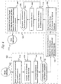
- FIG 4 is a flow chart which illustrates one example of a mode of operation for recorder 18 during the automatic calibration process.
- Controller 30 executes a software program implementing the logical steps illustrated in the flow chart of Figure 4.
- Phase 102 includes the logical steps of the exposure optimization phase while phase 104 includes the logical steps of the exposure linearization phase.
- Controller 30 begins the calibration process at starting step 100 and immediately proceeds to step 110 which sets the exposure level of radiation source 32 to a low initial level. Step 110 also fixes the target dot area, such as 50% as illustrated in the exposure optimization test pattern of Figure 2.
- controller 30 proceeds to step 120 and causes recorder 18 to form a first image area 60 1 (Fig. 2) of the exposure optimization test pattern.
- Controller proceeds to step 130 and increments the exposure setting of radiation source 32. Controller repeats steps 120 and 130 until each image area 60 1 through 60 10 is formed and decision step 140 is satisfied.
- controller 30 proceeds to step 150 and calculates the optimal exposure based on density readings from densitometer 34 as described in detail above. Controller 30 then enters the exposure linearization phase 104 by proceeding to step 160.
- controller 30 sets the exposure intensity of radiation source 32 to the optimal exposure level as determined in step 150. Controller 30 repeats steps 170, 180 and 190 until radiation source 32 completely forms grayscale 65 of Figure 3 including image regions 70 1 through 70 10 . Each image area 70 of grayscale 65 has a different target dot area as described above. For example, the corresponding dot areas range from 10% to 100% in the embodiment illustrated in Figure 3. While forming the exposure optimization test pattern of Figure 3, the exposure level of radiation source 32 is fixed at the optimal exposure level that was set during the first phase of the calibration process.
- controller 30 proceeds to step 200 and calculates a dot area error for each image area 70 based on density readings from densitometer 34. Based on the calculated dot error for each image area 70, controller 30 generates a linearization mechanism, such as lookup table or a function, that minimizes error by mapping a target dot area to a corresponding actual dot area. Controller 30 then exits the exposure linearization phase in termination step 210.
- a linearization mechanism such as lookup table or a function
- the present invention may be used to determine an optimal exposure for an imagesetter having a radiation source.
- the present invention contemplates the automatic linearization of the exposure level without requiring operator intervention.
- the linearization mechanisms achieved by the calibration techniques contemplated by the present invention may be applied by the recorder, may be communicated to the raster image processor for application at the RIP level, or may involve a cooperative calibration scheme by both components.
- the described method and device are suitable for calibrating a halftone imagesetter that forms latent images on a photosensitive imaging element and incorporates a processor for chemical processing and developing of the imaging element.
- the present invention is suitable for imagesetters and recorders that use other media including photothermographic and thermographic media.
- the present invention also contemplates simplified optimization and linearization of the exposure level of an imagesetter based on parameterized sensitometric characteristics of the imaging element. Accordingly, this application is intended to cover any adaptations or variations of the present invention.
Landscapes
- Engineering & Computer Science (AREA)
- Multimedia (AREA)
- Signal Processing (AREA)
- Facsimile Image Signal Circuits (AREA)
- Accessory Devices And Overall Control Thereof (AREA)
- Color, Gradation (AREA)
- Fax Reproducing Arrangements (AREA)
Claims (7)
- Verfahren zum Kalibrieren eines Rasterbildaufzeichnungssystems, das eine Strahlungsquelle zum Belichten eines Abbildungselements aufweist, wobei das Verfahren folgende Schritte umfasst:und wobei das Verfahren weiterhin folgende Schritte aufweist:Bilden einer ersten Vielzahl von Bildbereichen auf einem Abbildungselement mit der Strahlungsquelle, so dass jeder Bildbereich durch mindestens eine entsprechende Rasterzelle definiert ist, wobei die Rasterzellen unterschiedlicher Bildbereiche eine identische Sollpunktfläche aufweisen und durch die Strahlungsquelle mit unterschiedlichen Belichtungsstärken belichtet werden;Bemessen einer entsprechenden Dichte für jeden Bildbereich;Festlegen einer optimalen Belichtungsstärke für das Rasterbildaufzeichnungssystem in Abhängigkeit von den bemessenen Dichten für die ersten Bildbereiche;Festlegen der optimalen Belichtungsstärke für das Bildaufzeichnungssystem, basierend auf einem Vergleich zwischen der Sollpunktfläche und einer Istpunktfläche für die jeweiligen Bildbereiche der ersten Vielzahl von Bildbereichen;Bilden einer zweiten Vielzahl von Bildbereichen auf dem Abbildungselement, so dass jeder Bildbereich der zweiten Vielzahl von Bildbereichen durch mindestens eine entsprechende, eine Vielzahl von Punkten aufweisende Rasterzelle definiert ist, wobei die Rasterzellen unterschiedlicher Bildbereiche der zweiten Vielzahl von Bildbereichen unterschiedliche Istpunktflächen aufweisen und durch die Strahlungsquelle mit der optimalen Belichtungsstärke belichtet werden; und Entwickeln eines Linearisierungsmechanismus zum Übertragen nachfolgender Sollpunktflächen auf entsprechenden Istpunktflächen, basierend auf einem Vergleich zwischen der Sollpunktfläche und einer Istpunktfläche für die jeweiligen Bildbereiche der zweiten Vielzahl von Bildbereichen.
- Verfahren nach Anspruch 1, dadurch gekennzeichnet, dass der Festlegungsvorgang folgende Schritte aufweist:Bemessen einer Mindestdichte für eine bildfreie Fläche des Abbildungselements;Berechnen einer Istpunktfläche für jeden Bildbereich in Abhängigkeit von der bemessenen Dichte jedes Bildbereichs und der bemessenen Mindestdichte; undFestlegen der optimalen Belichtungsstärke, basierend auf einer Differenz zwischen der Sollpunktfläche und der berechneten Istpunktfläche jedes Bildbereichs.
- Verfahren nach Anspruch 2, dadurch gekennzeichnet, dass der Schritt zum Festlegen der optimalen Belichtungsstärke folgenden Schritt einschließt:Erzeugen einer Kurve, welche die Punktfläche als Funktion der Belichtung zeigt, basierend auf den berechneten lstpunktflächen der Bildbereiche.
- Verfahren nach Anspruch 1, dadurch gekennzeichnet, dass der Schritt zum Festlegen der optimalen Belichtung folgende Schritte aufweist:Bemessen einer entsprechenden Dichte für jeden Bildbereich der ersten Vielzahl von Bildbereichen;Bemessen einer Mindestdichte für eine bildfreie Fläche des Abbildungselements;Berechnen der Istpunktfläche für jeden Bildbereich der ersten Vielzahl von Bildbereichen in Abhängigkeit von der bemessenen Dichte jedes Bildbereichs der ersten Vielzahl von Bildbereichen und der bemessenen Mindestdichte; undErzeugen einer Kurve, welche die Punktfläche als Funktion der Belichtung zeigt, basierend auf den berechneten Istpunktflächen für jeden Bildbereich der ersten Vielzahl von Bildbereichen.
- Verfahren nach Anspruch 1, dadurch gekennzeichnet, dass der Schritt zum Entwickeln eines Linearisierungsmechanismus folgende Schritte aufweist:Bemessen einer entsprechenden Dichte für jeden Bildbereich der zweiten Vielzahl von Bildbereichen;Bemessen einer Mindestdichte für eine bildfreie Fläche des Abbildungselements;Berechnen der Istpunktfläche für jeden Bildbereich der zweiten Vielzahl von Bildbereichen in Abhängigkeit von der bemessenen Dichte jedes Bildbereichs der zweiten Vielzahl von Bildbereichen und der bemessenen Mindestdichte; undBerechnen eines Fehlers zwischen der Sollpunktfläche für jeden der Bildbereiche der zweiten Vielzahl von Bildbereichen und der berechneten Istpunktfläche für jeden der Bildbereiche der zweiten Vielzahl von Bildbereichen.
- Vorrichtung zum Kalibrieren eines Rasterbildaufzeichnungssystems gemäß dem Verfahren nach Anspruch 1, wobei die Vorrichtung folgende Komponenten umfasst:eine Strahlungsquelle zum Belichten des Abbildungselements;ein Densitometer zum Messen der Dichte des Abbildungselements; undeine mit der Strahlungsquelle und dem Densitometer verbundene Steuereinrichtung zur Durchführung folgender Schritte:(i) Steuern der Strahlungsquelle, um die erste Vielzahl von Bildbereichen auf dem Abbildungselement zu bilden, so dass jeder Bildbereich der ersten Vielzahl von Bildbereichen durch mindestens eine entsprechende Rasterzelle mit einer Vielzahl von Punkten definiert ist, wobei die Punkte der Rasterzellen unterschiedlicher Bildbereiche eine identische Sollpunktfläche aufweisen und durch die Strahlungsquelle mit unterschiedlichen Belichtungsstärken belichtet werden;(ii) Steuern des Densitometers, um für jeden Bildbereich der ersten Vielzahl von Bildbereichen eine entsprechende Dichte zu bemessen;(iii) Steuern des Densitometers, um für eine bildfreie Fläche des Abbildungselements eine Mindestdichte zu bemessen;(iv) Berechnen einer Istpunktfläche für jeden Bildbereich der ersten Vielzahl von Bildbereichen in Abhängigkeit von der bemessenen Dichte jedes Bildbereichs der ersten Vielzahl von Bildbereichen und der bemessenen Mindestdichte;(v) Festlegen einer optimalen Belichtungsstärke für das Bildaufzeichnungssystem, basierend auf einem Vergleich zwischen der Sollpunktfläche und der berechneten Istpunktfläche jedes Bildbereichs der ersten Vielzahl von Bildbereichen;(vi) Steuern der Strahlungsquelle, um die zweite Vielzahl von Bildbereichen auf dem Abbildungselement zu bilden, so dass jeder Bildbereich der zweiten Vielzahl von Bildbereichen durch mindestens eine entsprechende Rasterzelle mit einer Vielzahl von Punkten definiert ist, wobei die Rasterzellen unterschiedlicher Bildbereiche der zweiten Vielzahl von Bildbereichen unterschiedliche Sollpunktflächen aufweisen und durch die Strahlungsquelle mit der festgelegten, optimalen Belichtungsstärke belichtet werden;(vii) Steuern des Densitometers, um für jeden Bildbereich der zweiten Vielzahl von Bildbereichen eine entsprechende Dichte zu bemessen;(viii) Berechnen einer Istpunktfläche für jeden der Bildbereiche der zweiten Vielzahl von Bildbereichen in Abhängigkeit von der bemessenen Dichte jedes Bildbereichs der zweiten Vielzahl von Bildbereichen;(ix) Berechnen eines Fehlers zwischen der Sollpunktfläche für jeden der Bildbereiche der zweiten Vielzahl von Bildbereichen und der entsprechenden Istpunktfläche; und(x) Entwickeln des Linearisierungsmechanismus zum Übertragen nachfolgender Sollpunktflächen auf entsprechenden Istpunktflächen, basierend auf dem berechneten Fehler.
- Rasterbildaufzeichnungssystem, das in die Kalibrierungsvorrichtung nach Anspruch 6 eingebaut ist.
Applications Claiming Priority (3)
| Application Number | Priority Date | Filing Date | Title |
|---|---|---|---|
| US972102 | 1997-11-17 | ||
| US08/972,102 US6191867B1 (en) | 1997-11-17 | 1997-11-17 | Method and device for calibrating an imaging apparatus |
| PCT/US1998/024478 WO1999026407A1 (en) | 1997-11-17 | 1998-11-16 | Method and device for calibrating an imaging apparatus |
Publications (2)
| Publication Number | Publication Date |
|---|---|
| EP1033030A1 EP1033030A1 (de) | 2000-09-06 |
| EP1033030B1 true EP1033030B1 (de) | 2003-05-07 |
Family
ID=25519163
Family Applications (1)
| Application Number | Title | Priority Date | Filing Date |
|---|---|---|---|
| EP98960235A Expired - Lifetime EP1033030B1 (de) | 1997-11-17 | 1998-11-16 | Verfahren und vorrichtung zur kalibrierung eines bildaufzeichnungsgerätes |
Country Status (5)
| Country | Link |
|---|---|
| US (1) | US6191867B1 (de) |
| EP (1) | EP1033030B1 (de) |
| JP (1) | JP2001523603A (de) |
| DE (1) | DE69814450T2 (de) |
| WO (1) | WO1999026407A1 (de) |
Families Citing this family (19)
| Publication number | Priority date | Publication date | Assignee | Title |
|---|---|---|---|---|
| US6442497B1 (en) * | 2000-04-14 | 2002-08-27 | Eastman Kodak Company | Calibration method and strip for film scanners in digital photofinishing systems |
| GB0012457D0 (en) * | 2000-05-22 | 2000-07-12 | Priest Mark | Calibrating printing machines |
| US6803937B2 (en) * | 2000-05-23 | 2004-10-12 | Noritsu Koki Co., Ltd. | Photographic printer having varied intensities or optical modulation data for laser light sources |
| US6906828B2 (en) * | 2000-12-28 | 2005-06-14 | Xerox Corporation | Method and system of individualizing tone-reproduction curves calibration and applying thereof |
| US7142332B2 (en) * | 2000-12-28 | 2006-11-28 | Xerox Corporation | Method and system of individualizing tone-reproduction curves calibration and applying thereof |
| US6628426B2 (en) * | 2001-05-22 | 2003-09-30 | Lexmark International, Inc. | Method of halftone screen linearization via continuous gradient patches |
| EP1280333A1 (de) * | 2001-07-24 | 2003-01-29 | Imip Llc | Automatische Bestimmung einer Bildqualität |
| JP3866072B2 (ja) * | 2001-10-10 | 2007-01-10 | 大日本スクリーン製造株式会社 | ラスタライズ処理装置、ラスタライズ処理方法、および記録媒体並びにプログラム |
| US6789870B2 (en) * | 2002-05-24 | 2004-09-14 | Hewlett-Packard Development Company, L.P. | Drop quantity calibration method and system |
| US7206099B2 (en) * | 2002-07-16 | 2007-04-17 | Xerox Corporation | Media/screen look-up-table for color consistency |
| JP2004086809A (ja) * | 2002-08-29 | 2004-03-18 | Fuji Xerox Co Ltd | 画像形成システム、バックエンドプロセッサ |
| US6883892B2 (en) * | 2002-10-31 | 2005-04-26 | Hewlett-Packard Development Company, L.P. | Printing apparatus calibration |
| US8665487B2 (en) * | 2004-04-30 | 2014-03-04 | Hewlett-Packard Development Company, L.P. | Calibration of half-tone densities in printers |
| WO2006032272A1 (en) * | 2004-09-22 | 2006-03-30 | Esko-Graphics A/S | Method of evaluating the exposure level of a light sensitive material |
| US7375740B2 (en) * | 2005-07-25 | 2008-05-20 | Xerox Corporation | Method and apparatus for adjusting printbar uniformity |
| US9785873B2 (en) | 2016-02-16 | 2017-10-10 | Ricoh Company, Ltd. | Halftone calibration mechanism |
| US11184504B2 (en) | 2017-02-16 | 2021-11-23 | Ricoh Company, Ltd. | Dynamic printing system compensation mechanism |
| US10442211B2 (en) | 2017-02-21 | 2019-10-15 | Ricoh Company, Ltd. | Dual pass uniformity printing compensation mechanism |
| US11216710B1 (en) * | 2020-08-18 | 2022-01-04 | Ricoh Company, Ltd. | Iterative uniformity compensation mechanism |
Family Cites Families (23)
| Publication number | Priority date | Publication date | Assignee | Title |
|---|---|---|---|---|
| JPS59216165A (ja) * | 1983-05-25 | 1984-12-06 | Canon Inc | 光プリンタの露光量制御装置 |
| US4583128A (en) | 1984-08-27 | 1986-04-15 | Minnesota Mining And Manufacturing Company | Continuous tone recording system incorporating feedback control circuit |
| US5345315A (en) | 1988-11-23 | 1994-09-06 | Imatec, Ltd. | Method and system for improved tone and color reproduction of electronic image on hard copy using a closed loop control |
| US4999673A (en) | 1989-05-10 | 1991-03-12 | Xerox Corporation | Process control by creating and sensing half-tone test patches |
| EP0426435B1 (de) | 1989-10-31 | 1997-01-15 | Canon Kabushiki Kaisha | Bilderzeugungsgerät zur Halbtonwiedergabe |
| US5099276A (en) | 1990-01-30 | 1992-03-24 | Dainippon Screen Mfg. Co., Ltd. | Method of controlling exposure of process camera using sub-exposure and apparatus therefor |
| US5260806A (en) | 1990-08-29 | 1993-11-09 | E. I. Du Pont De Nemours And Company | Process for controlling tone reproduction |
| US5245443A (en) | 1990-10-02 | 1993-09-14 | Southwest Software, Inc. | Method and apparatus for calibrating image output from an image generating device |
| US5170257B1 (en) | 1990-10-02 | 1995-02-07 | Southwest Software Inc | Method and apparatus for calibrating halftone output from an image-setting device |
| KR930007256A (ko) | 1991-09-10 | 1993-04-22 | 오오가 노리오 | 작동메뉴를 나타내는 비디오 디스플레이장치 및 그의 텔레비전 수상기 |
| US5309246A (en) | 1991-09-18 | 1994-05-03 | Eastman Kodak Company | Technique for generating additional colors in a halftone color image through use of overlaid primary colored halftone dots of varying size |
| US5255085A (en) * | 1991-10-25 | 1993-10-19 | Eastman Kodak Company | Adaptive technique for providing accurate tone reproduction control in an imaging system |
| US5258810A (en) | 1991-12-13 | 1993-11-02 | Minnesota Mining And Manufacturing Company | Method for calibrating an electrophotographic proofing system |
| US5262825A (en) | 1991-12-13 | 1993-11-16 | Minnesota Mining And Manufacturing Company | Density process control for an electrophotographic proofing system |
| DE4303081C2 (de) * | 1992-02-18 | 1995-07-13 | Hell Ag Linotype | Verfahren und Einrichtung zur Belichtungs-Kalibrierung von Aufzeichnungsgeräten |
| JP2598598B2 (ja) | 1992-02-18 | 1997-04-09 | ライノタイプ−ヘル アクチエンゲゼルシャフト | 記録装置を露光較正する方法および装置 |
| AU661205B2 (en) | 1992-11-25 | 1995-07-13 | Eastman Kodak Company | Multi-user digital laser imaging system |
| US5508826A (en) | 1993-04-27 | 1996-04-16 | Lloyd; William J. | Method and apparatus for calibrated digital printing using a four by four transformation matrix |
| US5416613A (en) * | 1993-10-29 | 1995-05-16 | Xerox Corporation | Color printer calibration test pattern |
| EP0679946A1 (de) | 1994-04-19 | 1995-11-02 | Canon Kabushiki Kaisha | Bilderzeugungsverfahren |
| US5649073A (en) | 1995-12-28 | 1997-07-15 | Xerox Corporation | Automatic calibration of halftones |
| CA2171574C (en) * | 1996-03-12 | 2000-10-03 | Brian W. Tansley | Photometric measurement apparatus |
| US5883985A (en) * | 1996-12-10 | 1999-03-16 | General Electric Company | Method for compensating image data to adjust for characteristics of a network output device |
-
1997
- 1997-11-17 US US08/972,102 patent/US6191867B1/en not_active Expired - Lifetime
-
1998
- 1998-11-16 JP JP2000521643A patent/JP2001523603A/ja active Pending
- 1998-11-16 WO PCT/US1998/024478 patent/WO1999026407A1/en not_active Ceased
- 1998-11-16 EP EP98960235A patent/EP1033030B1/de not_active Expired - Lifetime
- 1998-11-16 DE DE69814450T patent/DE69814450T2/de not_active Expired - Lifetime
Also Published As
| Publication number | Publication date |
|---|---|
| DE69814450T2 (de) | 2004-03-18 |
| EP1033030A1 (de) | 2000-09-06 |
| US6191867B1 (en) | 2001-02-20 |
| JP2001523603A (ja) | 2001-11-27 |
| DE69814450D1 (de) | 2003-06-12 |
| WO1999026407A1 (en) | 1999-05-27 |
Similar Documents
| Publication | Publication Date | Title |
|---|---|---|
| US6191867B1 (en) | Method and device for calibrating an imaging apparatus | |
| US5936741A (en) | Method and apparatus for calibrating image output from an image generating device | |
| US5731884A (en) | Method of an apparatus for outputting halftone dot image | |
| US5189441A (en) | Image forming apparatus having density control | |
| US4965672A (en) | Method and apparatus for halftone imaging | |
| US5170257A (en) | Method and apparatus for calibrating halftone output from an imagesetting device | |
| US7130076B2 (en) | Image output device and test chart for the same | |
| US6618158B1 (en) | Method and device for calibrating an imaging apparatus having multiple imaging outputs | |
| EP0515162B1 (de) | Bildverarbeitungsverfahren und -gerät | |
| US5212560A (en) | Electrophotographic image forming apparatus comprising means for automatically adjusting image reproduction density | |
| EP0794656B1 (de) | Einstellung der Punktgrösse für Laserdrucker | |
| US20050111016A1 (en) | Image recording apparatus, management apparatus, color proof creating system, computer program product and light intensity correction method for image recording apparatus | |
| KR20080081817A (ko) | 화상 형성 장치 및 그 제어 방법 | |
| JPH06206341A (ja) | レーザープリンタを校正する方法 | |
| US5959650A (en) | Apparatus for forming an image with use of electrophotographic process | |
| JP2003094732A (ja) | 画像記録装置の較正方法および画像記録装置 | |
| US20070097440A1 (en) | Partial dot error diffusion halftone calibration | |
| US8614830B2 (en) | Pixel exposure as a function of subpixels | |
| JPH07131651A (ja) | 画像形成装置 | |
| JP3843336B2 (ja) | 階調補正方法及びその方法を採用したカラー画像プリンタ | |
| JPH04217280A (ja) | レーザビームプリンタ | |
| JPH07131652A (ja) | 画像形成装置 | |
| US6820551B1 (en) | Method and system for electronically generating exposure scale for laser imaging devices | |
| JPH03271779A (ja) | デジタル画像形成法 | |
| JP2005324393A (ja) | 画像形成装置および該装置のセットアップ方法 |
Legal Events
| Date | Code | Title | Description |
|---|---|---|---|
| PUAI | Public reference made under article 153(3) epc to a published international application that has entered the european phase |
Free format text: ORIGINAL CODE: 0009012 |
|
| 17P | Request for examination filed |
Effective date: 20000506 |
|
| AK | Designated contracting states |
Kind code of ref document: A1 Designated state(s): DE FR GB |
|
| 17Q | First examination report despatched |
Effective date: 20020628 |
|
| GRAH | Despatch of communication of intention to grant a patent |
Free format text: ORIGINAL CODE: EPIDOS IGRA |
|
| GRAH | Despatch of communication of intention to grant a patent |
Free format text: ORIGINAL CODE: EPIDOS IGRA |
|
| GRAA | (expected) grant |
Free format text: ORIGINAL CODE: 0009210 |
|
| AK | Designated contracting states |
Designated state(s): DE FR GB |
|
| REG | Reference to a national code |
Ref country code: GB Ref legal event code: FG4D |
|
| REF | Corresponds to: |
Ref document number: 69814450 Country of ref document: DE Date of ref document: 20030612 Kind code of ref document: P |
|
| ET | Fr: translation filed | ||
| PLBE | No opposition filed within time limit |
Free format text: ORIGINAL CODE: 0009261 |
|
| STAA | Information on the status of an ep patent application or granted ep patent |
Free format text: STATUS: NO OPPOSITION FILED WITHIN TIME LIMIT |
|
| 26N | No opposition filed |
Effective date: 20040210 |
|
| PGFP | Annual fee paid to national office [announced via postgrant information from national office to epo] |
Ref country code: FR Payment date: 20041105 Year of fee payment: 7 |
|
| PGFP | Annual fee paid to national office [announced via postgrant information from national office to epo] |
Ref country code: GB Payment date: 20051004 Year of fee payment: 8 |
|
| PG25 | Lapsed in a contracting state [announced via postgrant information from national office to epo] |
Ref country code: FR Free format text: LAPSE BECAUSE OF NON-PAYMENT OF DUE FEES Effective date: 20060731 |
|
| REG | Reference to a national code |
Ref country code: FR Ref legal event code: ST Effective date: 20060731 |
|
| GBPC | Gb: european patent ceased through non-payment of renewal fee |
Effective date: 20061116 |
|
| PG25 | Lapsed in a contracting state [announced via postgrant information from national office to epo] |
Ref country code: GB Free format text: LAPSE BECAUSE OF NON-PAYMENT OF DUE FEES Effective date: 20061116 |
|
| PGFP | Annual fee paid to national office [announced via postgrant information from national office to epo] |
Ref country code: DE Payment date: 20121130 Year of fee payment: 15 |
|
| REG | Reference to a national code |
Ref country code: DE Ref legal event code: R119 Ref document number: 69814450 Country of ref document: DE Effective date: 20140603 |
|
| PG25 | Lapsed in a contracting state [announced via postgrant information from national office to epo] |
Ref country code: DE Free format text: LAPSE BECAUSE OF NON-PAYMENT OF DUE FEES Effective date: 20140603 |