EP1033101A2 - Appareil de nettoyage électrique multi-usages avec poignée pliable pour sols, murs, meubles rembourrés et utilisations similaires - Google Patents
Appareil de nettoyage électrique multi-usages avec poignée pliable pour sols, murs, meubles rembourrés et utilisations similaires Download PDFInfo
- Publication number
- EP1033101A2 EP1033101A2 EP99102969A EP99102969A EP1033101A2 EP 1033101 A2 EP1033101 A2 EP 1033101A2 EP 99102969 A EP99102969 A EP 99102969A EP 99102969 A EP99102969 A EP 99102969A EP 1033101 A2 EP1033101 A2 EP 1033101A2
- Authority
- EP
- European Patent Office
- Prior art keywords
- handle
- cleaner
- fork
- extensions
- purpose electric
- Prior art date
- Legal status (The legal status is an assumption and is not a legal conclusion. Google has not performed a legal analysis and makes no representation as to the accuracy of the status listed.)
- Withdrawn
Links
Images


Classifications
-
- A—HUMAN NECESSITIES
- A47—FURNITURE; DOMESTIC ARTICLES OR APPLIANCES; COFFEE MILLS; SPICE MILLS; SUCTION CLEANERS IN GENERAL
- A47L—DOMESTIC WASHING OR CLEANING; SUCTION CLEANERS IN GENERAL
- A47L9/00—Details or accessories of suction cleaners, e.g. mechanical means for controlling the suction or for effecting pulsating action; Storing devices specially adapted to suction cleaners or parts thereof; Carrying-vehicles specially adapted for suction cleaners
- A47L9/32—Handles
- A47L9/322—Handles for hand-supported suction cleaners
-
- A—HUMAN NECESSITIES
- A47—FURNITURE; DOMESTIC ARTICLES OR APPLIANCES; COFFEE MILLS; SPICE MILLS; SUCTION CLEANERS IN GENERAL
- A47L—DOMESTIC WASHING OR CLEANING; SUCTION CLEANERS IN GENERAL
- A47L9/00—Details or accessories of suction cleaners, e.g. mechanical means for controlling the suction or for effecting pulsating action; Storing devices specially adapted to suction cleaners or parts thereof; Carrying-vehicles specially adapted for suction cleaners
- A47L9/32—Handles
- A47L9/325—Handles for wheeled suction cleaners with steering handle
Definitions
- the invention concerns electric domestic appliances for cleaning purposes in general by means of suction.
- Electric brooms namely appliances designed to replace the ordinary brooms, consisting of a head, covered with natural or artificial filaments fixed to the end of a handle, that sweeps up the dirt to a point where it can be collected.
- the electric broom is more convenient and efficient as it draws up the dirt instead of sweeping it, after which it is filtered into a bag placed for the purpose inside the appliance.
- This appliance can obviously be used to clean not only floors but also remove dust from articles of furniture such as the various forms of padded seating.
- the handle should either be fully extended to cover the distance between operator and floor or else be stowed out of the way when the appliance is used for padded furniture in which case it is more convenient to hold it by a laterally placed handle situated substantially at the centre of gravity of the appliance.
- Purpose of the above invention is to devise a way of changing from one position to another so as to satisfy functional and aesthetic necessities as will now be explained.
- Subject of the invention is a multi-purpose electric cleaner for floors, walls, padded furniture and the like.
- the fold-away handle turned on a hinge at the top, can be used in two positions: one, here called the open position when the cleaner is used for floors and walls, practically aligned with the axis of the body of the appliance, and the other, here called the closed position, when the appliance is used particularly for cleaning padded furniture or is out of use, when it can be stowed away in a recess made in the back of the body, said recess being of substantially the same shape and size as the handle.
- the handle When the appliance is closed, the handle can be fitted inside the volume of the appliance and so practically "disappear".
- the handle is shaped substantially like a tuning fork with prongs that form a fork the arms of which are articulated at the upper end of the sides of the body of the cleaner.
- a handgrip At the centre of the "tuning fork” is a handgrip whose end, when the cleaner is in its closed position, fits into a seat in the above recess made in the body of the cleaner, while the central portion of the handgrip is raised to allow the hand to grasp it.
- the body of the invented electric cleaner is tapered to make it more manageable, especially for cleaning padded furniture, when held by a handle placed laterally at the front substantially at said body's centre of gravity.
- the hinge on the handle in relation to the body of the cleaner, is formed of a transversal shaft having a cross-shaped section, fixed to said handle by a pair of convex heads with hollow extensions whose external shape and internal cavities are both cross-shaped.
- the hinge is therefore assembled by inserting said extensions into the holes in the arms of the handle while the ends of the shaft are inserted into the internal crosswise cavity in said extensions.
- the assembled parts are held in place by screws that pass through an axial hole in the convex heads and are tightened in holes at the ends of the shaft.
- Length of said extensions is greater than the thickness of the arms of the fork, it being possible to circumscribe said extensions by a circle.
- the part of the extensions emerging from the arms, towards the inside of the fork, is used to permit rotation of the whole piece, consisting of the shaft, the fork of the handle and the extensions, inside the circular housings created by opposing semicircles in the upper ends of the two matching halves of the electric cleaner.
- transversal locking disk on whose rim are two open radial notches the position of which corresponds to the two positions - open and closed - of the handle.
- Said two positions can be locked by the internal tooth of a slider control device with an internal head, said slider translating parallel to the shaft inside a slit made at the upper end of the body of the cleaner where the two halves match.
- a support Inside said slider control device is a support with a cylindrical cavity to take a helical compression spring that, making contact with a bracket on the body of the cleaner, tends to keep the slider, and therefore its internal tooth, opposite to the locking disk so that said tooth fits into one or other of the notches according to the position desired for the handle.
- Said spring ensures spontaneous stability of this lock which can be easily undone by pressing with the fingers on the external head of the slider in the direction opposite to the extension of the spring.
- the motor can advantageously be replaced by another of different power and size, this being done by simply reversing the motor's upper stabilizing plate comprising a square tubular body which, by means of a transversal baffle forming two superimposed and aligned chambers of equal transversal area but of different depth that open one on either side of the plate, creates space for a small head with a cavity of a size suitable for housing the head of the motor.
- the plate can be placed inside the body of the cleaner in one position, or in another overturned in relation to the first, so that the chamber of greater depth is available for the motor of greater length.
- the invention offers evident advantages.
- the appliance represents an excellent example of 'functional aesthetics'. Characteristics and purposes of the invention will be made still clearer by the following examples of its execution illustrated by diagrammatically drawn figures.
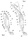
- the electric cleaner 10 comprises a body 11 and a foldaway handle 35 that can either be used in an extended position aligned with the body for cleaning floors, or be folded away in the rear of said body assuming its closed position, when cleaning padded furniture or when out of use.
- Said body 11 consists of two halves, 12 and 13, one front and one back that match at a line marked 19.
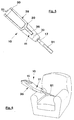
- a brush 50 or other accessories, such as the nozzle 51 (Fig. 6), can be fitted on as required at the lower mouth 17.
- a handgrip 14 is provided, raised above a bowl-shaped recess 16 to receive the hand.
- the shape of the foldaway handle 35 is substantially that of a tuning fork, with arms 37 in the form of a "U” and a central handgrip 36, articulated in the hinge 30 at the top of the body 11 of the appliance.
- a groove 20 (see also Fig. 5) runs along the upper part of the rear half 13 of the body, shaped to correspond with the fork of the handle 35 which, in the closed position, perfectly fits into said groove and practically “disappears" inside the volume of said half 13 of the body.
- the end 38 of the handgrip 36 of the handle 35 fits almost completely into the central part 39 (Figs 4 and 5) of said groove 20, the central part 40 of said handgrip being slightly raised to allow space for the fingers.
- the handle fits into the groove 20 and practically "disappears", from both the aesthetic and functional standpoints, since it thereby becomes an integral part of said body 11, thus facilitating (Fig. 6) use of the appliance, when held by the lateral handgrip 14, further favoured by its compact and rounded shape.
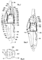
- the depression 16 under the handgrip 14 is formed of the cover over the filter 111 placed on the concave grill 120 fixed to the edges of the aperture 121 by means 122.
- Substantially behind said depression 16 is the motor 105 supported by a lower plate 118, with a grill filter 113 fixed to the supports 114 and 115 placed respectively on the opposing internal walls of the halves 12 and 13 of the appliance.
- Said plate 100 comprises the square tubular body 101 which, with the baffle 102, forms two chambers, an upper one 103 and a lower one 104, of equal transversal area but different depth, to house a small head 108 whose cylindrical cavity is sized to receive the head 107 of the motor 105.
- the motor 105 can be replaced by one of lower power indicated by 106 in Figure 8.
- the plate 100 To insert this latter motor the plate 100 must be turned over. The head 108 is then inserted into chamber 103 which, when the plate is overturned, becomes the lower one and is therefore closer to the lower plate 188 to compensate for the lesser height of that motor.
- An insulating pad 112 is fixed between the motor and the wall of the rear half 13 of the appliance.
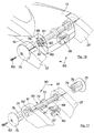
- the hinge for the fork-shaped handle 35 is formed of the shaft 60 with a crosswise transversal section, by means of convex heads 75 mounted on extensions shaped like a cross both inside 79 and out 76.
- the dimensions and shape of the external cross 76 correspond to those of the cross-shaped holes 32 through the ends of the arms 37 of the handle 35 while the dimensions and shape of the internal cross-shaped cavity 79 correspond to those of the cross-shaped ends of the shaft 60.
- Said extensions 76 of the convex heads 75 become inserted in the holes 31 in the arms of the fork, while the ends of the shaft 60 fit into the cross-shaped cavity 79 of said extensions 76.
- This assembly is made stable by screws 63 that screw into the threaded axial hole 62 made in the cylindrical axial body 61, present at said ends.
- Length of said extensions 76 is greater than the width of the arms of the handle 35 and they project inward from said arms and, as they can be circumscribed by a circle, they are used to permit rotation of the fork 37 of the handle 35 in the circular space created by the two semicircles 68 and 69 present in the upper ends of the halves 12 and 13 of the body of the electric cleaner.
- a slider device 85 is placed at the upper end of the body where the two halves 12 and 13 match, said device having an inner tooth 91 that can translate parallel to said shaft 60 when the fingers of the hand press on the head 84 with a curved side Said slider 85 can be moved from its inactive position (Fig. 16) to a position (Fig. 15) locking the handle so that it is aligned with the body of the appliance or turned back on it, this being done by overcoming resistance from the helical compression spring 90 inside the housing 89 in the lower part of said slider 85.
- the hand To rotate the handle from the open to the closed position, the hand must necessarily press the slider device 85 to free the tooth 91 from the notch 71 leaving the slider free to permit entry of tooth 91 in the other notch 72. To return to the open position these movements are made in the reverse order.
- the slider device 85 moves in the guide 18 through the square tang 87 joining said slider to the lower body 88 housing the spring 90 and carrying the locking tooth 91.
- the on-off switch 56, the knob 55 to vary suction power by means of the electronic card 58, the device 57 for opening the door in front of the bag 28 with its supporting plate 29, are all situated in the lower part of the cleaner.
Landscapes
- Engineering & Computer Science (AREA)
- Mechanical Engineering (AREA)
- Electric Vacuum Cleaner (AREA)
- Farming Of Fish And Shellfish (AREA)
Applications Claiming Priority (2)
| Application Number | Priority Date | Filing Date | Title |
|---|---|---|---|
| ITMI990025 | 1999-01-12 | ||
| ITMI990025 IT1306930B1 (it) | 1999-01-12 | 1999-01-12 | Scopa elettrica multiuso con manico ribaltabile,a scomparsa,perpavimenti,pareti,imbottiti e simili |
Publications (2)
| Publication Number | Publication Date |
|---|---|
| EP1033101A2 true EP1033101A2 (fr) | 2000-09-06 |
| EP1033101A3 EP1033101A3 (fr) | 2002-09-18 |
Family
ID=11381435
Family Applications (1)
| Application Number | Title | Priority Date | Filing Date |
|---|---|---|---|
| EP99102969A Withdrawn EP1033101A3 (fr) | 1999-01-12 | 1999-02-15 | Appareil de nettoyage électrique multi-usages avec poignée pliable pour sols, murs, meubles rembourrés et utilisations similaires |
Country Status (2)
| Country | Link |
|---|---|
| EP (1) | EP1033101A3 (fr) |
| IT (1) | IT1306930B1 (fr) |
Cited By (8)
| Publication number | Priority date | Publication date | Assignee | Title |
|---|---|---|---|---|
| WO2004103144A1 (fr) * | 2003-05-20 | 2004-12-02 | De' Longhi Spa | Dispositif de nettoyage electrique multi-fonctions |
| EP1190660A3 (fr) * | 2000-09-22 | 2005-03-30 | Daewoo Electronics Corporation | Aspirateur versatile |
| EP1795105A1 (fr) * | 2005-12-08 | 2007-06-13 | Hoover Limited | Aspirateur |
| US7281298B2 (en) * | 2004-03-24 | 2007-10-16 | Samsung Gwangju Electronics Co., Ltd. | Upright vacuum cleaner with foldable handle |
| GB2447527A (en) * | 2006-12-29 | 2008-09-17 | Kwonnie Electrical Products Lt | Handle arrangement for a floor sweeping apparatus |
| US10285548B2 (en) | 2014-06-30 | 2019-05-14 | Bissell Homecare, Inc. | Vacuum cleaner |
| CN110916556A (zh) * | 2019-12-27 | 2020-03-27 | 索立沃电器(苏州)有限公司 | 一种隐藏手持机的立式二合一吸尘器 |
| EP3847936A1 (fr) * | 2020-01-10 | 2021-07-14 | LG Electronics Inc. | Appareil de nettoyage |
Family Cites Families (6)
| Publication number | Priority date | Publication date | Assignee | Title |
|---|---|---|---|---|
| US3758914A (en) * | 1971-10-06 | 1973-09-18 | Whirlpool Co | Vacuum cleaner with movable handle structure |
| DE3435878A1 (de) * | 1984-09-29 | 1986-04-10 | Licentia Patent-Verwaltungs-Gmbh, 6000 Frankfurt | Staubsauger mit einer schwenkbaren handhabe |
| US4644605A (en) * | 1985-03-25 | 1987-02-24 | Bissell Inc. | Stick vacuum cleaner |
| US4660246A (en) * | 1986-04-14 | 1987-04-28 | The Singer Company | Versatile vacuum cleaning appliance |
| DE3700559C1 (en) * | 1987-01-10 | 1987-09-03 | Wolfgang Wagner | Hand vacuum cleaner (upright vacuum cleaner) |
| US5144716A (en) * | 1988-10-07 | 1992-09-08 | Hitachi, Ltd. | Electric cleaner, method for producing same and mount base and bumper for electric cleaner |
-
1999
- 1999-01-12 IT ITMI990025 patent/IT1306930B1/it active
- 1999-02-15 EP EP99102969A patent/EP1033101A3/fr not_active Withdrawn
Cited By (13)
| Publication number | Priority date | Publication date | Assignee | Title |
|---|---|---|---|---|
| EP1190660A3 (fr) * | 2000-09-22 | 2005-03-30 | Daewoo Electronics Corporation | Aspirateur versatile |
| US7171724B2 (en) | 2003-05-20 | 2007-02-06 | De' Longhi Spa | Multifunctional electric cleaning apparatus |
| CN100337575C (zh) * | 2003-05-20 | 2007-09-19 | 德隆奇有限公司 | 多功能电清洁装置 |
| WO2004103144A1 (fr) * | 2003-05-20 | 2004-12-02 | De' Longhi Spa | Dispositif de nettoyage electrique multi-fonctions |
| US7281298B2 (en) * | 2004-03-24 | 2007-10-16 | Samsung Gwangju Electronics Co., Ltd. | Upright vacuum cleaner with foldable handle |
| US7681279B2 (en) | 2005-12-08 | 2010-03-23 | Hoover Limited | Vacuum cleaner |
| EP1795105A1 (fr) * | 2005-12-08 | 2007-06-13 | Hoover Limited | Aspirateur |
| GB2447527A (en) * | 2006-12-29 | 2008-09-17 | Kwonnie Electrical Products Lt | Handle arrangement for a floor sweeping apparatus |
| GB2447527B (en) * | 2006-12-29 | 2011-08-10 | Kwonnie Electrical Products Ltd | Floor cleaning apparatus with elongate handle and handle extension |
| US10285548B2 (en) | 2014-06-30 | 2019-05-14 | Bissell Homecare, Inc. | Vacuum cleaner |
| US11337571B2 (en) | 2014-06-30 | 2022-05-24 | Bissell Inc. | Vacuum cleaner |
| CN110916556A (zh) * | 2019-12-27 | 2020-03-27 | 索立沃电器(苏州)有限公司 | 一种隐藏手持机的立式二合一吸尘器 |
| EP3847936A1 (fr) * | 2020-01-10 | 2021-07-14 | LG Electronics Inc. | Appareil de nettoyage |
Also Published As
| Publication number | Publication date |
|---|---|
| IT1306930B1 (it) | 2001-10-11 |
| EP1033101A3 (fr) | 2002-09-18 |
| ITMI990025A1 (it) | 2000-07-12 |
Similar Documents
| Publication | Publication Date | Title |
|---|---|---|
| USD444604S1 (en) | Paint tray with storable carrying handles | |
| AU2001232024B2 (en) | Hose and wand assembly | |
| EP2521474B1 (fr) | Ensemble de direction pour dispositif de nettoyage de surfaces | |
| CN100593387C (zh) | 真空吸尘器 | |
| RU2488342C2 (ru) | Узел рукоятки для всасывающего узла | |
| EP3610767B1 (fr) | Aspirateur de type à manche maniable | |
| USD447609S1 (en) | Combined wet/dry vacuum cleaner dolly and accessory storage unit | |
| US20050012307A1 (en) | Compact wagon or cart including stowable wheels and handle | |
| US20060070208A1 (en) | Multifunctional electric cleaning apparatus | |
| EP1033101A2 (fr) | Appareil de nettoyage électrique multi-usages avec poignée pliable pour sols, murs, meubles rembourrés et utilisations similaires | |
| WO1999030604A1 (fr) | Aspirateur | |
| US6536072B2 (en) | Compression latch for dirt cup | |
| USD469614S1 (en) | Long-handled scrub brush | |
| AU2009202139B2 (en) | Upright type cleaner | |
| US4683607A (en) | Vacuum cleaner accessory bracket | |
| KR100429478B1 (ko) | 전기청소기 | |
| USD506856S1 (en) | Vacuum cleaner | |
| US2573091A (en) | Combined vacuum cleaner and tool casing | |
| USD509590S1 (en) | Tongue cleaner with pivotably foldable handle | |
| WO2001003565A1 (fr) | Suceur d'aspirateur de poussiere articule et aspirateur equipe d'un tel suceur | |
| JP2006025920A (ja) | 電気掃除機 | |
| CN218044960U (zh) | 一种可折弯连接组件、含有其的手柄组件及清洁器 | |
| KR100284243B1 (ko) | 전기청소기 | |
| CN214965055U (zh) | 手持式真空吸尘器 | |
| KR100228867B1 (ko) | 전기 소제기 |
Legal Events
| Date | Code | Title | Description |
|---|---|---|---|
| PUAI | Public reference made under article 153(3) epc to a published international application that has entered the european phase |
Free format text: ORIGINAL CODE: 0009012 |
|
| AK | Designated contracting states |
Kind code of ref document: A2 Designated state(s): AT BE CH CY DE DK ES FI FR GB GR IE IT LI LU MC NL PT SE |
|
| AX | Request for extension of the european patent |
Free format text: AL;LT;LV;MK;RO;SI |
|
| 17P | Request for examination filed |
Effective date: 20001127 |
|
| PUAL | Search report despatched |
Free format text: ORIGINAL CODE: 0009013 |
|
| AK | Designated contracting states |
Kind code of ref document: A3 Designated state(s): AT BE CH CY DE DK ES FI FR GB GR IE IT LI LU MC NL PT SE |
|
| AX | Request for extension of the european patent |
Free format text: AL;LT;LV;MK;RO;SI |
|
| 17Q | First examination report despatched |
Effective date: 20020113 |
|
| AKX | Designation fees paid |
Designated state(s): DE ES FR |
|
| STAA | Information on the status of an ep patent application or granted ep patent |
Free format text: STATUS: THE APPLICATION IS DEEMED TO BE WITHDRAWN |
|
| 18D | Application deemed to be withdrawn |
Effective date: 20030524 |