EP1033151A2 - Übungsgerät - Google Patents
Übungsgerät Download PDFInfo
- Publication number
- EP1033151A2 EP1033151A2 EP00400576A EP00400576A EP1033151A2 EP 1033151 A2 EP1033151 A2 EP 1033151A2 EP 00400576 A EP00400576 A EP 00400576A EP 00400576 A EP00400576 A EP 00400576A EP 1033151 A2 EP1033151 A2 EP 1033151A2
- Authority
- EP
- European Patent Office
- Prior art keywords
- lever
- articulated
- central
- axis
- longitudinal
- Prior art date
- Legal status (The legal status is an assumption and is not a legal conclusion. Google has not performed a legal analysis and makes no representation as to the accuracy of the status listed.)
- Withdrawn
Links
- 230000006978 adaptation Effects 0.000 description 6
- 238000004806 packaging method and process Methods 0.000 description 2
- 235000008694 Humulus lupulus Nutrition 0.000 description 1
- 230000002411 adverse Effects 0.000 description 1
- 230000001143 conditioned effect Effects 0.000 description 1
- 230000000694 effects Effects 0.000 description 1
- 229920001971 elastomer Polymers 0.000 description 1
- 239000000806 elastomer Substances 0.000 description 1
- 238000000605 extraction Methods 0.000 description 1
- 238000012423 maintenance Methods 0.000 description 1
- 238000004519 manufacturing process Methods 0.000 description 1
- 239000000463 material Substances 0.000 description 1
- 238000012986 modification Methods 0.000 description 1
- 230000004048 modification Effects 0.000 description 1
- 238000003466 welding Methods 0.000 description 1
Images

Classifications
-
- A—HUMAN NECESSITIES
- A63—SPORTS; GAMES; AMUSEMENTS
- A63B—APPARATUS FOR PHYSICAL TRAINING, GYMNASTICS, SWIMMING, CLIMBING, OR FENCING; BALL GAMES; TRAINING EQUIPMENT
- A63B22/00—Exercising apparatus specially adapted for conditioning the cardio-vascular system, for training agility or co-ordination of movements
- A63B22/0076—Rowing machines for conditioning the cardio-vascular system
- A63B2022/0082—Rowing machines for conditioning the cardio-vascular system with pivoting handlebars
- A63B2022/0084—Rowing machines for conditioning the cardio-vascular system with pivoting handlebars pivoting about a horizontal axis
Definitions
- the present invention relates to an apparatus for performing physical exercises, especially exercises similar to those developed in the practice of rowing, of the type comprising a frame including a longitudinal central beam that can be placed substantially in horizontal position in service, a seat mounted sliding on said beam, support means for the feet of the user, who are linked to the beam towards its front end, a lever articulated provided on at least one side of the beam, and a resistant means which connects said lever to the frame to slow down the movement of the lever controlled by the user.
- each lever is articulated on the frame so as to be able pivot around a vertical or substantially vertical pivot axis.
- each lever moves in a plane horizontal or substantially horizontal when operated by the user of the device. Under these conditions, the device allows the user to carry out movements almost identical to those which would be carried out by handling the oars of a real boat to oars.
- the two levers simulating the oars have necessarily a certain length and as they extend roughly horizontally and transversely with respect to the median axis longitudinal of the central beam of the frame of the device, the cross built on the ends of which the two are articulated respectively levers must itself have a relatively large length. It As a result, the device has a relatively large size in width and that, in order to be easily stored or transported, the frame of the device must be made in a foldable form, which makes its more complicated and costly to manufacture and may adversely affect stability of the device.
- Such known devices have a space requirement width significantly smaller than that of the known device mentioned in the first place in which the levers are articulated so as to be able to pivot around a vertical or substantially vertical axis. In however, the movements it allows to perform are more distant of those that are actually performed by handling the oars of a real rowing boat.
- the present invention therefore aims to provide an apparatus of the above-mentioned genre, which allows both close to those performed by handling the oars of a real rowing boat, while having a space requirement in width relatively small.
- the apparatus according to the invention is characterized in that the pivot axis of the lever makes a predetermined angle, less than 90 °, with the longitudinal median axis of the said central beam longitudinal, so that the free end of the lever, provided a handle that can be grasped by the user, is located in or at immediate proximity to the vertical plane containing the median axis longitudinal of said beam, when the lever is pushed into its position extreme forward, and is moved away from said vertical plane when said lever is pulled into its extreme rear position.
- the apparatus according to the invention can include, like the apparatuses known, two articulated levers arranged respectively on the side and on the other side of the longitudinal central beam of the frame, a resistant means being associated with each articulated lever.
- the pivot axis of each of the two articulated levers then makes said predetermined angle with the axis longitudinal median of said central beam, and this so symmetrical with respect to said longitudinal median axis.
- the aforementioned predetermined angle can be between 82 ° and 86 °.
- the aforementioned predetermined angle may have a fixed value which is chosen so that when the two levers are pulled into their extreme rear position, the handles of the levers are spaced from each other by a distance corresponding to a value average shoulder widths of users.
- said predetermined angle may be approximately equal to 84 °.
- the frame of the apparatus may advantageously comprise, in addition, two crosspieces fixed in their middle to the longitudinal central beam, transversely thereto while being spread in the direction longitudinal.
- Each lever can then be articulated on the face upper of one of the two crosspieces, near one of its ends outside or at selectable locations along the crosspiece to allow the above adjustment according to the user morphology.
- That of the two crosspieces on which the two are articulated levers can have an arcuate shape in a horizontal plane.
- the pivot axis of each lever can be substantially perpendicular to the radius of the arc which is formed by the arched cross member and which passes through the location where the lever is articulated on said crosspiece arched.
- each of the two levers can be articulated on the frame, for example on the crosspiece arched above, by means of a two-degree articulation of freedom ; a first of the two degrees of freedom corresponds to said axis of pivoting which makes said predetermined angle with the median axis longitudinal of the longitudinal central beam; the second degree of freedom can be provided by a second horizontal pivot axis or substantially horizontal, which is perpendicular to the first axis of pivoting.
- Such an arrangement also allows adaptation of the device, more precisely an adaptation of the spacing of the lever handles at the width of the user's shoulders. This adaptation can be done automatically in operation if each lever is left free, in use, to pivot around said second axis of pivoting.
- said adaptation is done before each use of the device, for example at using a joint with two degrees of freedom including the second degree of freedom can be blocked, for example using as a second axis swivel a bolt-nut assembly with operating knob for tightening the bolt or nut.
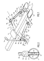
- the apparatus 1 comprises a frame 2 comprising a central beam 3 longitudinal.
- the beam 3 has a hollow, rectangular or square.
- Two crosspieces 4 and 5 are fixed, in the middle, to the face bottom of beam 3.
- the two crosspieces 4 and 5 are spaced in the longitudinal direction of the beam 3 and oriented in a direction orthogonal or substantially orthogonal to the longitudinal axis of said beam.
- the crosspiece 4 preferably has an arcuate shape in a horizontal plane and is roughly in the middle of the length of the beam 3.
- Cross member 5, which is shorter than cross member 4, is straight and is near the front end of beam 3.
- the sleepers 4 and 5 preferably consist of hollow sections, which have, in the example of embodiment shown, a round section but could also have a rectangular cross section or square.
- the two crosspieces 4 and 5 of the frame 2 serve as feet for support for this frame, when it is placed on the ground.
- the crosspieces 4 and 5 may comprise, at each of their ends, non-slip elements (not shown) for example in material elastomer.
- a third support leg (not shown) may still be provided, if desired, at the rear end of beam 3.
- a seat 6 is slidably mounted on the beam 3, towards the rear of this one.
- the guidance and the maintenance of the seat 6 can be ensured by guiding and holding means which are conventional and which, for this reason were not shown.
- these means of guiding and holding can consist of wings making projection on the edges of the upper surface of the beam 3, cooperating with rollers provided under the seat 6, as described, for example, in document EP-A-0 681 854.
- support means 7 are provided for the feet of the user.
- These support means 7 comprise, for example, a footrest 7a, 7b provided on each side of the beam 3 and provided optionally, straps for clamping the foot.
- the footrests 7 a and 7 b are fixed, in a known manner, to the lateral faces of the beam 3 or to the cross-member 5.
- each lever 8 a , 8 b articulated at its lower end on a horizontal axis 9 a , 9 b , fixed to the upper face of the cross member 4 in a manner which will be described in detail more far.
- Each lever 8 a, 8 b is provided at its free upper end, a handle 11, 11b facing towards the inside.
- a resistant means advantageously constituted by a hydraulic damper 12 a , 12 b , connects each lever 8 a , 8 b to the frame 2.
- Each damper 12 a , 12 b comprises a cylinder 13 a or 13 b and a rod 14 a or 14 b of piston.
- Each cylinder 13 a, 13 b is provided, the frame side 2, an eyelet 15 a, 15 b, articulated by a horizontal axis 16a, 16b on a clevis 17 a, 17 b fixed to the cross member 5 at one end of the latter.
- Each piston rod 14 a , 14 b is provided with an eyelet which is articulated by an axis 18 a , 18 b on a yoke 19 a , 19 b carried by the corresponding lever 8 a , 8 b .
- each yoke 19, 19b can be displaced along the lever 8 a, 8 b corresponding and immobilized in any desired position along thereof with a locking known means (not shown) to to adjust the force multiplier effect of the corresponding lever 8 a , 8 b , therefore in order to adjust the resistant force felt by the user of the device 1 when he actuates the levers 8 a and 8 b .
- the pivot axis 9 a , 9 b of each lever 8 a , 8 b makes a predefined angle ⁇ (FIG. 3) with the longitudinal median axis 20 of the beam 3.
- This angle ⁇ is chosen in such a way that the handles 11 a and 11 b of the levers 8 a and 8 b lie in the vertical median plane of the beam 3, as shown in the right part of FIG. 1, or close to this vertical median plane, as shown in FIG.
- the angle ⁇ can be fixed.
- the yokes 21 a and 21 b which respectively carry the axes 9 a and 9 b can be rigidly fixed, for example by welding, to the cross member 4 near the ends of the latter.
- care must be taken that the axis 9 a is parallel to the axis 16 a and that axis 9 b is parallel to axis 16 b .
- each yoke can be provided with a cylindrical tail 22, as illustrated in FIG. 2 in connection with the yoke 21 a .
- the crosspieces 4 and 5 comprise, in correspondence with each of the yokes 21 a , 21 b and 17 a , 17 b , two holes 23 and 24 aligned, of vertical axis, in which is engaged and fixed a sheath 25 suitable for receiving the cylindrical tail 22 of the yoke 21 a , 21 b , 17 a or 17 b concerned.
- Locking means for example means cooperating by elastic snap-fastening, can be provided respectively on the cylindrical tail 22 and in the sheath 25 to axially retain the tail 22 in the sheath 25 after it has been engaged therein, but while allowing the extraction of said rod out of said sheath, if necessary, by exerting a predefined axial traction on the corresponding yoke.
- the yokes 17 a and 17 b are closer to the longitudinal central axis 20 than the yokes 21 a and 21 b .
- the angle ⁇ can be adjustable.
- each of the two yokes 17 a and 17 b can be fixed to the cross-member 5 in a manner similar to that shown in FIG. 2 in connection with the yoke 21 a , so that they can pivot around the vertical axis of their respective tails 22.
- the cross-member 4 can be provided, in the region of each of its ends, with a series of pairs of holes 23, 24, each containing a sheath 25 , as in Figure 2.
- the value of the angle ⁇ can be set in the range of 82 ° to 86 °.
- each of the two yokes 21 a and 21 b could be secured to a slide which can slide in a slide fastened to the cross-member 4 or formed therein.
- each lever 8 a , 8 b is articulated on the cross-member 4 by means of an articulation having two degrees of freedom, for example an articulation of the universal joint type as the joint 26 a shown in FIG. 4.
- the joint 26 a comprises a first yoke 21 a , which is similar to the yoke 21 a of the embodiment described above and which is fixed to the cross member 4, for example d in a manner similar to that shown in Figure 2.
- the yoke 21 has a door axis 9 on which is articulated a second yoke 27 a carrying a second pivot axis 28 is orthogonal to the pivot axis 9a .
- the lever 8 a is articulated on this second pivot axis 28 a .
- the spacing of the handles 11 a and 11 b of the two levers 8 a and 8 b can be set to any desired value and adapted to the morphology of the user, in particular the width of his shoulders.
- the levers 8 a and 8 b free to pivot around the corresponding axis 28 a , the abovementioned adaptation can be done automatically and at any time during the use of the device.
- the adaptation can be made before each use, for each user, by providing a locking means making it possible to lock, in a releasable manner, the lever 8 a , 8 b in a desired angular position relative to clevis 27 a .
- the pivot axis 28 a can be constituted by a bolt and nut assembly, the bolt or the nut being provided with an operating button so that, by tightening the bolt or the nut with the using the operating button, the angular position of the lever 8 a , 8 b relative to the yoke 27 a can be fixed.
- the cross-member 4 can have a total length equal to that of the two crosspieces of the apparatus described, by example in document EP-A-0 681 854, while the cross-member 5 may have a shorter length than that of the known device. It therefore results that the device according to the invention has a space requirement in width of the same order of magnitude or even less than that of the known device mentioned above.
- the articulation 26 a with two degrees of freedom can be combined with the embodiment of the device shown in FIG. 3, in which a series of holes 23 at each end of the cross-member 4.
- a tube for example rectilinear, telescopic; this tube has a central part welded under the central beam and two end parts capable of sliding inside the central part, an appropriate locking means being provided to prevent or release the sliding.
- This locking means can be a pin and, in this case, the central part can comprise, on each side of the central beam, a hole, while each end part comprises a plurality of holes, the introduction of the pin in the holes allowing symmetrically to block the end parts with respect to the central part.
- the articulation of the levers (of the type 8 a , 8 b ) relative to the cross member is then carried out at a determined point of each of the end parts of the cross member and the adjustment of the angle ⁇ results from the positioning of the parts end of the crosspiece with respect to the central part of said crosspiece.
- This articulation can in particular be produced as provided for the device of FIG. 1 or the device of FIG. 4.
- the advantage of this variant is that, for the packaging of the device, there is less space since the crosspiece which carries the lever joints can be conditioned in the disassembled state, resulting in a smaller packaging size.
- the tubes used for the realization of the sleepers of the device can have a cross section any, in particular circular or square.
Landscapes
- Health & Medical Sciences (AREA)
- Cardiology (AREA)
- Vascular Medicine (AREA)
- General Health & Medical Sciences (AREA)
- Physical Education & Sports Medicine (AREA)
- Orthopedics, Nursing, And Contraception (AREA)
- Special Chairs (AREA)
- Chairs Characterized By Structure (AREA)
- Rehabilitation Tools (AREA)
Applications Claiming Priority (2)
| Application Number | Priority Date | Filing Date | Title |
|---|---|---|---|
| FR9902694 | 1999-03-04 | ||
| FR9902694A FR2790397B1 (fr) | 1999-03-04 | 1999-03-04 | Appareil pour effectuer des exercices physiques |
Publications (2)
| Publication Number | Publication Date |
|---|---|
| EP1033151A2 true EP1033151A2 (de) | 2000-09-06 |
| EP1033151A3 EP1033151A3 (de) | 2003-03-26 |
Family
ID=9542819
Family Applications (1)
| Application Number | Title | Priority Date | Filing Date |
|---|---|---|---|
| EP00400576A Withdrawn EP1033151A3 (de) | 1999-03-04 | 2000-03-03 | Übungsgerät |
Country Status (2)
| Country | Link |
|---|---|
| EP (1) | EP1033151A3 (de) |
| FR (1) | FR2790397B1 (de) |
Cited By (2)
| Publication number | Priority date | Publication date | Assignee | Title |
|---|---|---|---|---|
| DE20308565U1 (de) | 2003-04-29 | 2003-08-14 | Lai, Fen-Ying, Taichung | Zusammenklappbarer Rudersimulator |
| US7666123B2 (en) * | 2001-11-13 | 2010-02-23 | Cybex International, Inc. | Upper torso exercise machine |
Citations (3)
| Publication number | Priority date | Publication date | Assignee | Title |
|---|---|---|---|---|
| EP0095226A2 (de) | 1982-05-25 | 1983-11-30 | Brown Fitzpatrick Lloyd Patent Limited | Verwandelbares Übungsgerät |
| GB2191103A (en) | 1986-05-30 | 1987-12-09 | Demka Guernsey Limited | Rowing machine |
| EP0681854A1 (de) | 1994-05-09 | 1995-11-15 | Emile Mannet | Übungsvorrichtung |
Family Cites Families (6)
| Publication number | Priority date | Publication date | Assignee | Title |
|---|---|---|---|---|
| FR765712A (de) * | 1934-06-13 | |||
| NL7305550A (de) * | 1972-04-26 | 1973-10-30 | ||
| US4650181A (en) * | 1986-01-21 | 1987-03-17 | Yang Tzu Tsan | Dynamic rowing machine |
| US4750736A (en) * | 1986-05-05 | 1988-06-14 | Weslo, Inc. | Multipurpose exercise machine |
| US4836532A (en) * | 1986-12-04 | 1989-06-06 | Kuo Hai P | Rowing exerciser |
| US4768775A (en) * | 1987-07-13 | 1988-09-06 | Frank E. Marshall | Combination rowing machine and chest exerciser |
-
1999
- 1999-03-04 FR FR9902694A patent/FR2790397B1/fr not_active Expired - Fee Related
-
2000
- 2000-03-03 EP EP00400576A patent/EP1033151A3/de not_active Withdrawn
Patent Citations (3)
| Publication number | Priority date | Publication date | Assignee | Title |
|---|---|---|---|---|
| EP0095226A2 (de) | 1982-05-25 | 1983-11-30 | Brown Fitzpatrick Lloyd Patent Limited | Verwandelbares Übungsgerät |
| GB2191103A (en) | 1986-05-30 | 1987-12-09 | Demka Guernsey Limited | Rowing machine |
| EP0681854A1 (de) | 1994-05-09 | 1995-11-15 | Emile Mannet | Übungsvorrichtung |
Cited By (2)
| Publication number | Priority date | Publication date | Assignee | Title |
|---|---|---|---|---|
| US7666123B2 (en) * | 2001-11-13 | 2010-02-23 | Cybex International, Inc. | Upper torso exercise machine |
| DE20308565U1 (de) | 2003-04-29 | 2003-08-14 | Lai, Fen-Ying, Taichung | Zusammenklappbarer Rudersimulator |
Also Published As
| Publication number | Publication date |
|---|---|
| FR2790397A1 (fr) | 2000-09-08 |
| FR2790397B1 (fr) | 2004-03-12 |
| EP1033151A3 (de) | 2003-03-26 |
Similar Documents
| Publication | Publication Date | Title |
|---|---|---|
| EP3421658B1 (de) | Dampfbügel- und/oder entknitterungsgerät, das ein bügelbrett umfasst, das in verschiedenen neigungswinkeln festgestellt werden kann | |
| FR2458297A1 (fr) | Equipement d'entrainement physique | |
| FR3010683A3 (de) | ||
| CH666613A5 (fr) | Engin de levage pour invalide. | |
| FR3010684A3 (de) | ||
| FR2649372A1 (fr) | Siege a dossier reversible | |
| WO1986000054A1 (fr) | Chariot a deux roues a traction humaine par timon souple | |
| FR2581956A1 (fr) | Dispositif resultant de la combinaison d'une trottinette avec une bicyclette, actionne par le poids du conducteur | |
| EP1033151A2 (de) | Übungsgerät | |
| FR2590538A1 (fr) | Appareil d'entrainement d'une charge en rotation par pedalage vers l'avant en position horizontale, applicable plus particulierement aux bicyclettes | |
| EP0521775A1 (de) | Tragbare Vorrichtung zum Richten von Rohren | |
| FR2511879A1 (fr) | Appareil a ramer | |
| CA1140613A (fr) | Velo a cadre telescopique adaptable en velo d'appartement | |
| FR2514649A1 (fr) | Appareil d'entrainement a pedales | |
| FR2831127A1 (fr) | Engin de glisse pour sport de neige | |
| FR3041312A1 (fr) | Poignee pliante de poussette pour enfant | |
| EP0798201A2 (de) | Mono- oder Tandem- Stadtfahrrad/- Roller für Damen und Herren | |
| FR3101604A1 (fr) | Trottinette pliable | |
| EP0681854B1 (de) | Übungsvorrichtung | |
| EP0096633B1 (de) | Kombination von zylindricalem Fass und Karren zum Aufrichten | |
| FR2795652A1 (fr) | Chariot pliable pour sac de golf, possedant des moyens de verrouillage perfectionnes | |
| FR2869284A1 (fr) | Chassis de chariot a guidage bi-fonctionnel | |
| FR2796358A1 (fr) | Tricycle inclinable | |
| FR2673820A1 (fr) | Dispositif unitaire comprenant un siege et une table. | |
| WO2007006985A1 (fr) | Voilier a mat inclinable |
Legal Events
| Date | Code | Title | Description |
|---|---|---|---|
| PUAI | Public reference made under article 153(3) epc to a published international application that has entered the european phase |
Free format text: ORIGINAL CODE: 0009012 |
|
| AK | Designated contracting states |
Kind code of ref document: A2 Designated state(s): AT BE CH CY DE DK ES FI FR GB GR IE IT LI LU MC NL PT SE |
|
| AX | Request for extension of the european patent |
Free format text: AL;LT;LV;MK;RO;SI |
|
| PUAL | Search report despatched |
Free format text: ORIGINAL CODE: 0009013 |
|
| AK | Designated contracting states |
Kind code of ref document: A3 Designated state(s): AT BE CH CY DE DK ES FI FR GB GR IE IT LI LU MC NL PT SE Designated state(s): AT BE CH CY DE DK ES FI FR GB GR IE IT LI LU MC NL PT SE |
|
| AX | Request for extension of the european patent |
Extension state: AL LT LV MK RO SI |
|
| AKX | Designation fees paid | ||
| REG | Reference to a national code |
Ref country code: DE Ref legal event code: 8566 |
|
| STAA | Information on the status of an ep patent application or granted ep patent |
Free format text: STATUS: THE APPLICATION IS DEEMED TO BE WITHDRAWN |
|
| 18D | Application deemed to be withdrawn |
Effective date: 20030927 |