EP1033215A2 - Vorrichtung zum Herstellen von Treppen - Google Patents
Vorrichtung zum Herstellen von Treppen Download PDFInfo
- Publication number
- EP1033215A2 EP1033215A2 EP00103731A EP00103731A EP1033215A2 EP 1033215 A2 EP1033215 A2 EP 1033215A2 EP 00103731 A EP00103731 A EP 00103731A EP 00103731 A EP00103731 A EP 00103731A EP 1033215 A2 EP1033215 A2 EP 1033215A2
- Authority
- EP
- European Patent Office
- Prior art keywords
- tread
- riser
- assembly
- mould part
- mould
- Prior art date
- Legal status (The legal status is an assumption and is not a legal conclusion. Google has not performed a legal analysis and makes no representation as to the accuracy of the status listed.)
- Withdrawn
Links
- 238000000465 moulding Methods 0.000 title claims abstract description 21
- 238000000429 assembly Methods 0.000 claims abstract description 23
- 230000000712 assembly Effects 0.000 claims abstract description 23
- 230000007246 mechanism Effects 0.000 claims description 28
- 239000000463 material Substances 0.000 claims description 9
- 238000000034 method Methods 0.000 claims description 9
- 238000005266 casting Methods 0.000 claims description 3
- 230000015572 biosynthetic process Effects 0.000 description 10
- 238000005755 formation reaction Methods 0.000 description 10
- 230000002787 reinforcement Effects 0.000 description 3
- 230000004048 modification Effects 0.000 description 2
- 238000012986 modification Methods 0.000 description 2
- 230000005540 biological transmission Effects 0.000 description 1
- 238000010276 construction Methods 0.000 description 1
- 230000000694 effects Effects 0.000 description 1
- 239000000945 filler Substances 0.000 description 1
- 239000012530 fluid Substances 0.000 description 1
- 238000003754 machining Methods 0.000 description 1
- 238000007493 shaping process Methods 0.000 description 1
Images



Classifications
-
- E—FIXED CONSTRUCTIONS
- E04—BUILDING
- E04F—FINISHING WORK ON BUILDINGS, e.g. STAIRS, FLOORS
- E04F11/00—Stairways, ramps, or like structures; Balustrades; Handrails
-
- B—PERFORMING OPERATIONS; TRANSPORTING
- B28—WORKING CEMENT, CLAY, OR STONE
- B28B—SHAPING CLAY OR OTHER CERAMIC COMPOSITIONS; SHAPING SLAG; SHAPING MIXTURES CONTAINING CEMENTITIOUS MATERIAL, e.g. PLASTER
- B28B7/00—Moulds; Cores; Mandrels
- B28B7/22—Moulds for making units for prefabricated buildings, i.e. units each comprising an important section of at least two limiting planes of a room or space, e.g. cells; Moulds for making prefabricated stair units
- B28B7/225—Moulds for making units for prefabricated buildings, i.e. units each comprising an important section of at least two limiting planes of a room or space, e.g. cells; Moulds for making prefabricated stair units for making stairs or stair units comprising more than one step
Definitions
- This invention relates to an apparatus and method of moulding a staircase in using a castable material such as concrete.
- Prior European Patent 0191711 describes one such mould in which the lengths of tread and riser mould parts in the mould are adjustable so that the treads and risers of the staircase can have desired dimensions.
- the treads and risers are provided as modular assemblies and the treads and risers of the individual modules are independently adjustable This is a very time consuming and skilled process because, to ensure that in the resulting staircase, all of the treads and risers respectively, are of a consistent length and comply with accepted building standards, it is necessary to perform detailed calculations and then accurately to perform adjustments to each module.
- the mould is lined in this proposal, with a continuous liner wrapped around rollers to ensure that the liner is kept taught, which complicates the adjustment process.
- an apparatus for moulding a staircase including a plurality of tread and riser mould part assemblies arranged along the apparatus, each tread mould part of each assembly extending downwardly from a connection with the riser mould part of the assembly, which riser mould part also extends downwardly at an opposite side of the connection, the lengths of each of the tread and riser mould parts from their respective connections being adjustable, and the apparatus further including a support structure characterised in that the tread mould part of a first assembly and the riser mould part of an adjacent second assembly are connected to a first bogie means which is movable along the support structure of the apparatus, and the riser mould part of the first assembly and the tread mould part of a third adjacent assembly are connected to a second bogie means which is movable along the support structure of the apparatus, the lengths of the tread and riser mould parts of the first assembly and of the riser mould part of the second assembly and of the tread mould part of the third assembly being adjustable as the first and second bogie means are moved towards or away from one another.
- the tread and riser assemblies have been provided as individual modules, in the apparatus of the invention, the tread and riser assemblies are interconnected via the bogie means.
- the tread mould part of the second assembly is preferably connected to a further bogie means as is the riser mould part of the third assembly, all of the bogie means being moveable along the support structure whereby the lengths of all of the tread and riser mould parts may be adjusted upon relative movement of the respective bogie means.
- each tread and riser mould part assembly has an associated linkage mechanism including an adjustment member, the adjustment member being moveable to cause relative movement between the pair of adjacent bogie means to which the tread and riser mould parts are connected, or being moveable in response to relative movement between the pair of adjacent bogie means to cause adjustment of the length of at least one of the tread and riser mould parts.
- each linkage mechanism may include an adjustment member which is pivotally connected to one of the bogie means of the pair, and a link element which extends between and is pivotally connected to each of the adjustment member and a point adjacent to the tread and riser mould part connection.
- the adjustment members of each of the linkage mechanisms of the apparatus are moveable together whereby the lengths of all of the tread and/or riser mould parts of the apparatus may simultaneously adjust generally equally with the other respective tread and riser mould parts.
- each of the other tread and riser assemblies will be caused to be adjusted.
- the assemblies are interconnected, if the end closures of the apparatus are set in positions to provide a staircase of a desired length, the lengths of the treads and/or risers will automatically be set and accordingly much simpler calculation than with the previous proposal is required, it only being necessary to determine the number of steps required along the staircase for a given staircase length.
- the invention enables a variety of staircases to be produced using the apparatus, faster and with less skill than hithertofore.
- the adjustment members may each be moved in response to movement of an actuating means with which each of the adjustment members is engaged.
- the link element is connected at or towards one end to the point adjacent to the tread and riser mould part connection and at or towards the opposite end to the adjustment member intermediate the ends of the adjustment member.
- the adjustment member may be cranked along its length and the link element may be connected to the adjustment member in the region of the crank.
- Each linkage mechanism may include a further link fixed at or close to the point adjacent to the tread and riser mould part connection, which link is moveable independently of the adjustment member to cause adjustment of the length of the riser and/or tread mould part.
- the length of e.g. the treads may be adjusted by adjustment member movement, as a result of relative movement between the bogie means, and the lengths of the riser may be adjusted by movement of the further link.
- each bogie means may comprise a single bogie, which for a large staircase may entail additional support for the tread and riser mould part assemblies, preferably each bogie means includes a pair or pairs of bogies spaced laterally of the apparatus so that the assemblies are supported adequately across substantially their entire widths by the bogies.
- the bogies may comprise simple sliding members, but preferably each bogie has a pair of wheels or rollers which roll along a support rail of the support structure, to facilitate movement.
- Each tread and riser mould part assembly may include a liner which provides an interface between the tread and riser mould parts and the material to be cast into the mould, the liner extending over the connection between the tread and riser mould parts and being fixed with respect to either the tread or riser mould part of the assembly and being adjustable with respect to the riser or tread mould part to accommodate tread and riser mould part length adjustments.
- the liner may extend downwardly between a riser mould part of one assembly and the tread mould part of an adjacent assembly, and may be biased downwardly so that the liner remains taught during tread and riser mould part length adjustment.
- each of the adjacent tread and riser mould parts of adjacent assemblies are connected to the bogie means by a generally cylindrical connecting member which extends laterally of the apparatus, the liners of each of the adjacent tread and riser mould part assemblies passing extending around a respective cylindrical connecting member.
- a step nosing is formed between the cylindrical connecting members of the tread mould part of one assembly and the riser part of the adjacent assembly.
- a nosing insert including an upper part having a concave configuration which upper part spans any gap between the adjacent connecting members and partially overlaps the uppermost lined surfaces of the adjacent tread and riser mould parts, the nosing insert also having a lower part which extends downwardly from the upper part and is configured to engage the adjacent cylindrical members of the adjacent connecting members.
- a second aspect of the invention we provide a method of moulding using an apparatus according to the first aspect of the invention characterised in that alternate bogie means are moved towards or away from adjacent bogie means to adjust each of the tread and riser mould parts to a desired length, and the mould is closed to provide a moulding cavity between side and end mould closure members and a mould bottom formed by the plurality of tread and riser mould part assemblies, and moulding material is cast into the moulding cavity and permitted to harden.
- reinforcement elements may be provided which extend from one end of the apparatus to the other, and may be pre-stressed so that stress may be applied to the cast concrete when hardened.
- an apparatus 10 for moulding a staircase in e.g. concrete or other settable/hardenable material, which concrete etc. may be reinforced as desired and as is well known in the art, or as described hereinafter.
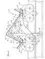
- the moulding apparatus 10 has a moulding cavity defined between side closure members 12, 13, end closure members (not seen) and a bottom wall provided by a plurality of tread and riser mould part assemblies 14.
- the side 12, 13 and end closure members and the assemblies 14 are supported by a support structure which includes bracing to hold the closure members rigid.
- a filler (not shown) may be positioned between the side closure members 12, 13 at any desired position laterally of the apparatus 10 to enable staircases of varying width to be produced.
- the support structure also enables the overall length of the moulding cavity between the end closure members to be adjusted, so that a staircase of a desired length may be produced.
- the number of steps of the staircase can be changed by adding/removing tread and riser mould part assemblies 14, and the geometry of the individual steps can be adjusted as hereinafter described, within limits, so that the moulding apparatus 10 may be used to produce staircases of widely varying dimensions.
- the support structure includes outer main rails 16, 17 arranged at the sides of the apparatus 10, and corresponding auxiliary inner rails 18, 18a, 19, 19a the rails all being supported on a base structure 20.
- Side support structures 21, 22 provide for bracing of the side closures 12, 13 respectively.
- the tread and riser mould part assemblies 14 each comprise a tread mould part 24 and a riser mould part 25, the mould parts 24, 25 being connected at a connection 26 at a fixed relative angle of 90° ⁇ 15°.
- Each of the tread and riser mould parts 24, 25 is adjustable in length downwardly from the connection 26, by virtue of being telescopic, the mould parts 24, 25 having outer parts 28, 29 and inner relatively slideable parts 30, 31 respectively.
- the inner parts 30, 31 may have a slot or slots therein which receives a guide pin (or pins) 33, 34 whereby the sliding movement of the inner part 30, 31 is guided.
- Fillers F may be provided as necessary to fill any surface discontinuity formed as the inner parts 33, 34 are telescoped outwardly, as seen in figure 1 only.
- the tread 24 and riser 25 mould parts are each connected at their ends 34, 35 to respective bogies 40, 41, at each side of the apparatus 10.
- the bogies 40, 41 at one side are movable along the rail 17 whereas the bogies 40, 41 at the other side are moveable along the rail 16.
- the bogies 40, 41 each are connected to cylindrical formations 46, 47 at the ends of the tread and riser mould parts 24, 25.
- Each bogie for example bogie 40, has connected thereto, a tread mould part 24 of a first assembly 14, and a riser 25 mould part of an adjacent assembly 14, and by virtue of the mounting of the cylindrical formations 46, 47 relative rotation and thus variance of the angle between the tread mould part 24 and the riser mould part 25 at each bogie 40 is permitted.
- tread and riser assemblies 14 are interconnected by the bogies 40, 41 and adjacent pairs of bogies 40 and 41 may be moved towards and away from one another along the respective rails 16, 17 to adjust the lengths of at least the tread mould parts 24 as the inner parts 30 thereof slide in or out relative to the outer parts 28.
- Such relative bogie movement may also cause some adjustment of the lengths of the riser mould parts 25, although in the main this is effected by other means as hereinafter explained.
- the bogies 40, 41 each comprise a pair of wheels W, but could alternatively be rollers or pairs of rollers or the like to facilitate movement of the bogies 40, 41 along the rails 16, 17.
- the tread and riser mould parts 24, 25 are further interconnected by linkage mechanisms 50.
- Each linkage mechanism 50 comprises, at each side of the apparatus 10, inwardly of the rails 16, 17, an adjustment member 51 which in this example is of cranked configuration, and is pivoted at one end 52 to a cylindrical formation 46 e.g. provided at the end of the tread mould part 24.
- the adjustment member 51 has a roller 54 which is carried on a lifting mechanism 60 supported on rails 18 a (or 19 a ) of the support structure. As lifting mechanism 60 is operated, the adjustment member 51 will be moved between the lower position shown in figure 2 and the upper position of figure 1.
- the adjustment member 51 is pivotally connected at A to a link 55 which extends to a point 56 adjacent to the connection 26 between the tread and riser mould parts 24,25, where the link 55 is pivotally connected.
- first lifting mechanisms 60 some riser mould part 25 length adjustment may occur, and during operation of the second lifting mechanisms 61, some tread mould part 24 length adjustment may occur but by providing both first and second lifting mechanisms 60, 61, which may be operated separately or together the tread and riser mould parts 24, 25 lengths can be relatively adjusted.
- the tread and/or riser mould parts 24, 25 respectively will all be adjusted simultaneously as the respective lifting mechanisms 60, 61 are operated. Further the tread mould parts 24 and riser mould parts 25 respectively will be adjusted generally equally, with the result that the staircase formed in the moulding apparatus 10 will have generally equally spaced steps i.e. the tread and riser dimensions will be consistent throughout the staircase, as is demanded by accepted building standards.
- the lifting mechanism 60, 61 may include respective rails R on which the rollers 54/58 bear, which rails are moved up or down by one or more hydraulic or other fluid operated actuators, or by an electric or other motive means, e.g. through a transmission, as desired.
- Each tread and riser assembly 14 has an associated liner L which extends over the connection 26 between the tread and riser mould parts 24, 25, and downwardly over and between adjacent cylindrical formations 46, 47 at the ends of tread and riser mould parts 24, 25.
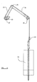
- the liner L is fixed at one end, e.g. by wrapping around the cylindrical formation 47 of the riser mould part 25 and is secured to a clamp block 62, which extends from side to side of the liner L, and at an opposite end the liner L depends between the cylindrical formations 46, 47 to a free hanging connector 63.
- the connector 63 extends throughout the liner L width, and is connected to weights 64 as illustrated in figure 4.
- the liner L is held taught as the bogies 40, 41 are moved along the rails 16, 17 to adjust the lengths of at least the tread mould parts 24.
- any alternative means for maintaining the liner L taught could be employed.
- this gap is in the region of a step nosing. It is important that the step nosing is properly formed, or else a machining or the like operation will subsequently be required.
- a nosing insert 70 (best seen in figure 5) is inserted in the gap, the insert 70 having an upper part with a concave formation 72 of the desired step nosing shape, the upper part having legs 74, 75 which overlap the uppermost surfaces of the tread and riser mould parts 24, 25.
- the insert 70 further has a lower part 76 which depends from the upper part and is configured generally to conform to the shape of the cylindrical formations 46, 47.
- the nosing insert 70 may have to be positioned from the side, before side closure plate 12 or 13 is in position, but preferably the insert 70 is made of a material, such as a suitable plastic or rubber which allows sufficient resilient deformation for the insert 70 to be positioned from above. In each case the insert 70 is securely held in position during casting by the legs 74, 75 and the cylindrical formations 46, 47.
- the geometry of the linkage mechanism 50 described is only an example as other geometries may be employed which permit of the simultaneous adjustment of each of the tread and/or riser mould parts 25 as described.
- the support structure may be adapted for a particular mould design, as may the construction and positioning of the bogies 40, 41 etc.
- tread and riser mould parts 24, 25 have been described as being adjustable in length by being telescopic, alternative arrangements are possible.
- the angle between the tread and riser mould pans 24, 25 at the connection 26 from which they each extend downwardly is fixed, but in another example, some adjustment of this angle within the range 75° to 105° may be permitted if desired.
- the apparatus 10 described is particularly for casting concrete staircases, but other castable/hardenable materials could be used, in which case some modification to the apparatus 10 may thus be required or desirable.
- the adjustable moulding apparatus 10 may have pre-stressed reinforcement members provided thereon, extending from one end of the apparatus to the other, e.g. as shown at M in figure 3.
- pre-stressed reinforcement members provided thereon, extending from one end of the apparatus to the other, e.g. as shown at M in figure 3.
Landscapes
- Engineering & Computer Science (AREA)
- Architecture (AREA)
- Civil Engineering (AREA)
- Structural Engineering (AREA)
- Manufacturing & Machinery (AREA)
- Chemical & Material Sciences (AREA)
- Ceramic Engineering (AREA)
- Mechanical Engineering (AREA)
- Steps, Ramps, And Handrails (AREA)
- Escalators And Moving Walkways (AREA)
- Moulds For Moulding Plastics Or The Like (AREA)
Applications Claiming Priority (2)
| Application Number | Priority Date | Filing Date | Title |
|---|---|---|---|
| GB9903959 | 1999-02-23 | ||
| GB9903959A GB2347106B (en) | 1999-02-23 | 1999-02-23 | Apparatus for moulding a staircase |
Publications (2)
| Publication Number | Publication Date |
|---|---|
| EP1033215A2 true EP1033215A2 (de) | 2000-09-06 |
| EP1033215A3 EP1033215A3 (de) | 2001-06-13 |
Family
ID=10848207
Family Applications (1)
| Application Number | Title | Priority Date | Filing Date |
|---|---|---|---|
| EP00103731A Withdrawn EP1033215A3 (de) | 1999-02-23 | 2000-02-22 | Vorrichtung zum Herstellen von Treppen |
Country Status (2)
| Country | Link |
|---|---|
| EP (1) | EP1033215A3 (de) |
| GB (1) | GB2347106B (de) |
Cited By (2)
| Publication number | Priority date | Publication date | Assignee | Title |
|---|---|---|---|---|
| CN110509411A (zh) * | 2019-08-21 | 2019-11-29 | 南京唐壹信息科技有限公司 | 一种装配式建筑用可拆卸式混凝土浇筑模具 |
| CN110883920A (zh) * | 2019-12-19 | 2020-03-17 | 浙江交工集团股份有限公司 | 一种预制t梁自行式液压模板装置及模板系统 |
Families Citing this family (4)
| Publication number | Priority date | Publication date | Assignee | Title |
|---|---|---|---|---|
| US8262055B2 (en) | 2006-09-12 | 2012-09-11 | Any Step Technology Limited | Stair forming apparatus and related methods |
| EP2066483B1 (de) * | 2006-09-12 | 2019-06-12 | Pap Limited | Treppenformungsvorrichtung und entsprechende verfahren |
| CN104972551A (zh) * | 2015-06-24 | 2015-10-14 | 中民筑友有限公司 | 一种楼梯模具的踏步组件及楼梯模具 |
| CN104924424A (zh) * | 2015-06-24 | 2015-09-23 | 中民筑友有限公司 | 一种楼梯模具的踏步组件及楼梯模具 |
Family Cites Families (4)
| Publication number | Priority date | Publication date | Assignee | Title |
|---|---|---|---|---|
| FR2576830B1 (fr) * | 1985-01-31 | 1987-04-17 | Colman Bernard | Moule reglable pour la fabrication d'elements en beton, par exemple des escaliers |
| GB2193922B (en) * | 1986-08-15 | 1989-12-20 | Bison Limited | Moulding concrete staircases |
| DE4342684C1 (de) * | 1993-12-15 | 1995-04-13 | Harald Schahl | Schalung zur Herstellung von Betontreppen |
| DE69606398T2 (de) * | 1996-02-27 | 2000-07-06 | Tarmac Heavy Building Materials Uk Ltd., Ettingshall | Vorrichtung und verfahren zum herstellen von treppen. |
-
1999
- 1999-02-23 GB GB9903959A patent/GB2347106B/en not_active Expired - Fee Related
-
2000
- 2000-02-22 EP EP00103731A patent/EP1033215A3/de not_active Withdrawn
Cited By (2)
| Publication number | Priority date | Publication date | Assignee | Title |
|---|---|---|---|---|
| CN110509411A (zh) * | 2019-08-21 | 2019-11-29 | 南京唐壹信息科技有限公司 | 一种装配式建筑用可拆卸式混凝土浇筑模具 |
| CN110883920A (zh) * | 2019-12-19 | 2020-03-17 | 浙江交工集团股份有限公司 | 一种预制t梁自行式液压模板装置及模板系统 |
Also Published As
| Publication number | Publication date |
|---|---|
| GB2347106A (en) | 2000-08-30 |
| GB2347106B (en) | 2003-07-02 |
| EP1033215A3 (de) | 2001-06-13 |
| GB9903959D0 (en) | 1999-04-14 |
Similar Documents
| Publication | Publication Date | Title |
|---|---|---|
| US8262055B2 (en) | Stair forming apparatus and related methods | |
| DE69524106T2 (de) | Vorrichtung zur herstellung eines profilträgers aus verbundwerkstoff | |
| EP2066483B1 (de) | Treppenformungsvorrichtung und entsprechende verfahren | |
| CN110394885B (zh) | 一种应用于箱涵预制的整体液压式模板 | |
| EP1033215A2 (de) | Vorrichtung zum Herstellen von Treppen | |
| JP7165592B2 (ja) | 鋳造管の砂型鋳込み装置及びその中子の金枠への位置決め方法 | |
| JP3620901B2 (ja) | プレキャストコンクリート製階段成形装置 | |
| KR100448221B1 (ko) | 암거 제작용 이동식 철재 거푸집장치 및 이를 이용한암거의 증기촉진양생 연속시공방법 | |
| GB2217359A (en) | Prestressed concrete staircases | |
| GB2193922A (en) | Moulding concrete staircases | |
| EP3056620A1 (de) | Befestigungsvorrichtung und Verfahren zur Montage eines Ausleger-Bauelements zu einer Kante einer Bodenkonstruktion eines Gebäudes | |
| JPH07279417A (ja) | 梁型枠装置および梁の施工方法 | |
| KR200265793Y1 (ko) | 박스 구조물 성형용 시스템 폼의 간격 조절장치 | |
| CN113580336B (zh) | 预制楼梯模具及预制楼梯的生产方法 | |
| CN111216218B (zh) | 铸造预制混凝土产品的侧成型单元和系统 | |
| JP2550885B2 (ja) | 階段の製造方法およびその型枠装置 | |
| CN116653093B (zh) | 一种多自由度预制楼梯操作平台及预制成型方法 | |
| JP2004204508A (ja) | 階段の構築方法及び階段用型枠 | |
| KR200279232Y1 (ko) | 아이엘엠용 박스거더 동시타설형 거푸집장치 | |
| CN113373808B (zh) | 钢护栏基座与桥面板一体化预制板、预制模板及施工方法 | |
| JP3048333B2 (ja) | 階段とその製造方法 | |
| EP0628389B1 (de) | Verfahren und Vorrichtung zur Herstellung von Bauteilen aus Beton | |
| CN110409805A (zh) | 一种基于bim的装配式建筑混凝土浇筑方法 | |
| KR200200942Y1 (ko) | 박스구조물 성형용 시스템폼 | |
| CN116587404B (zh) | 楼梯浇注一体成型模具 |
Legal Events
| Date | Code | Title | Description |
|---|---|---|---|
| PUAI | Public reference made under article 153(3) epc to a published international application that has entered the european phase |
Free format text: ORIGINAL CODE: 0009012 |
|
| AK | Designated contracting states |
Kind code of ref document: A2 Designated state(s): AT BE CH CY DE DK ES FI FR GB GR IE IT LI LU MC NL PT SE |
|
| AX | Request for extension of the european patent |
Free format text: AL;LT;LV;MK;RO;SI |
|
| PUAL | Search report despatched |
Free format text: ORIGINAL CODE: 0009013 |
|
| AK | Designated contracting states |
Kind code of ref document: A3 Designated state(s): AT BE CH CY DE DK ES FI FR GB GR IE IT LI LU MC NL PT SE |
|
| AX | Request for extension of the european patent |
Free format text: AL;LT;LV;MK;RO;SI |
|
| 17P | Request for examination filed |
Effective date: 20011030 |
|
| AKX | Designation fees paid |
Free format text: AT BE CH CY DE DK ES FI FR GB GR IE IT LI LU MC NL PT SE |
|
| RAP1 | Party data changed (applicant data changed or rights of an application transferred) |
Owner name: TARMAC LIMITED |
|
| 17Q | First examination report despatched |
Effective date: 20030220 |
|
| GRAP | Despatch of communication of intention to grant a patent |
Free format text: ORIGINAL CODE: EPIDOSNIGR1 |
|
| STAA | Information on the status of an ep patent application or granted ep patent |
Free format text: STATUS: THE APPLICATION IS DEEMED TO BE WITHDRAWN |
|
| 18D | Application deemed to be withdrawn |
Effective date: 20031222 |