EP1033430A2 - Halterung für eine Wäscheständerabdeckung - Google Patents
Halterung für eine Wäscheständerabdeckung Download PDFInfo
- Publication number
- EP1033430A2 EP1033430A2 EP00301817A EP00301817A EP1033430A2 EP 1033430 A2 EP1033430 A2 EP 1033430A2 EP 00301817 A EP00301817 A EP 00301817A EP 00301817 A EP00301817 A EP 00301817A EP 1033430 A2 EP1033430 A2 EP 1033430A2
- Authority
- EP
- European Patent Office
- Prior art keywords
- bracket
- clothes line
- arm
- cover
- mounting
- Prior art date
- Legal status (The legal status is an assumption and is not a legal conclusion. Google has not performed a legal analysis and makes no representation as to the accuracy of the status listed.)
- Withdrawn
Links
- 210000002105 tongue Anatomy 0.000 claims description 17
- 238000004873 anchoring Methods 0.000 claims description 5
- 230000002250 progressing effect Effects 0.000 claims description 3
- 241000239290 Araneae Species 0.000 description 3
- 230000000903 blocking effect Effects 0.000 description 1
- 238000000034 method Methods 0.000 description 1
- 238000000465 moulding Methods 0.000 description 1
Images


Classifications
-
- D—TEXTILES; PAPER
- D06—TREATMENT OF TEXTILES OR THE LIKE; LAUNDERING; FLEXIBLE MATERIALS NOT OTHERWISE PROVIDED FOR
- D06F—LAUNDERING, DRYING, IRONING, PRESSING OR FOLDING TEXTILE ARTICLES
- D06F57/00—Supporting means, other than simple clothes-lines, for linen or garments to be dried or aired
- D06F57/02—Supporting means, other than simple clothes-lines, for linen or garments to be dried or aired mounted on pillars, e.g. rotatably
- D06F57/04—Supporting means, other than simple clothes-lines, for linen or garments to be dried or aired mounted on pillars, e.g. rotatably and having radial arms, e.g. collapsible
Definitions
- This invention relates to apparatus.
- cover for a rotary clothes line the cover is mounted over the rotary clothes line by having a fixing bracket secured to each of the outwardly projecting arms of the rotary clothes line, with each of these brackets serving as a locator for a rod or spar which is coupled to the cover itself.
- the brackets are customarily made to be a snap fit onto the rotary arms.
- the brackets can be so designed that if the cover has a large force exerted on it, for example in high winds, the brackets will become unfixed from the rotary arms before those rotary arms suffer damage.
- Such a bracket is disclosed in W095/01476. However this bracket could be improved in a number of ways.
- a mounting bracket for mounting a clothes line cover on a clothes line arm, said bracket being comprised of an upper part and a lower part, said upper part having retaining means whereby said upper part is attachable to said cover, said lower part having anchoring means whereby said lower part is anchorable to said arm, characterised in that said upper part and said lower part have therebetween releasable connecting means whereby, with said cover attached to said arm by way of said bracket and when a predetermined force is applied to said upper part, said upper part is released from said lower part which remains anchored to said arm.
- a mounting bracket for mounting a clothes line cover on a clothes line arm, characterised in that said bracket includes a clamping device comprised of a pair of jaws of which at least one is openable and closable to receive an edge zone of said cover and to clamp said edge zone.
- a mounting bracket for mounting a clothes line cover on a clothes line arm, characterised in that said bracket is provided with a recess to receive an elongate member for mounting said cover, and said bracket extends around more than 180° of said recess.
- bracket can grip and retain the elongate member that mounts the cover, mounting of the cover over a spider of arms is made easier.
- a combination comprising a mounting bracket for mounting a clothes line cover, a clothes line arm, and a transverse member for locking said bracket to said arm, said bracket being provided with a cut-out below said arm, said cut-out being arranged to receive said member and to allow release of said bracket from said member and thus from said arm, when a predetermined force is applied to said bracket, characterised in that said cut-out has one or more of the following features:
- the cut-out does not need actually to be cut out from the bracket but is preferably moulded into the bracket which is advantageously a one-piece moulding.
- a mounting bracket for mounting a clothes line cover on a clothes line arm, said bracket having a channel bounding legs, characterised in that said channel, in a section taken in an upwardly extending plane progressing from the mouth of said channel, includes a substantially circular portion for closely receiving a clothes line arm of substantially circular cross-section followed by a substantially rectangular portion for closely receiving a clothes line arm of substantially rectangular cross-section.
- the mounting bracket can be fitted selectively to a clothes line arm of circular cross-section or a clothes line arm of rectangular cross-section.
- a kit comprising a bracket for connecting a clothes line cover to a clothes line arm, and a plurality of channelled inserts of channel cross-sections differing from each other for fitting in said bracket for accommodating respective clothes line arms of differing cross-sections.
- the bracket 1 includes a lower part 2 designed to be fitted onto a projecting arm of a rotary clothes line (not shown).
- the part 2 includes a pair of resilient legs 2a, 2b which define a channel 3 to house the supporting arm (not shown).
- the channel 3 is so shaped as to receive a circular cross-section arm (although it could additionally or alternatively be so shaped as to receive a rectangular cross-section arm) and to have a substantial surface area to grip the arm.
- Each of the legs 2a and 2b is provided with a horizontal through bore 4 which receives a transverse member in the form of a fastening bolt (not shown) of the bracket device. By tightening a nut on the bolt, the lower part 2 can be tightened onto the supporting arm. This gives a secure anchoring for all conditions of use.
- the bracket 1 further includes an upper part 5 and there is, between the lower part 2 and the upper part 5 a releasable connection 6.
- the connection 6 includes two tongues 7 and 8 extending from respective edges of a substantially flat underneath surface 5a of the part 5, these edges being respectively radially inner and radially outer with respect to the middle of the rotary clothes line.
- Each of the tongues 7 and 8 curves downwardly and inwardly, roughly parallelly to each other, the tongue 7 being of substantially constant cross-section, but the tongue 8 being formed with an inwardly projecting rib 9 at its free edge.
- the releasable connection 6 also includes a slot 10 at the radially inner and a groove 11 at the radially outer sides of the part 2.
- the slot 10 is of rectangular cross-section of a size relatively closely to receive the tongue 7 and is of a curved form to correspond to the curved shape of the tongue 7.
- the groove 11 is of a U-shaped cross-section corresponding to that of the rib 9 and is disposed at a distance from a substantially flat top surface 2c of the part 2 substantially equal to the distance at which the rib 9 is spaced from the surface 5a.
- the part 5 includes a clamping device 12 comprised of a lower jaw 13 and an upper jaw 14 interconnected at their radially outer edge by a hinge 15.
- the jaws 13 and 14 protrude laterally to a significant extent and both extend across the whole width of the part 5.
- the clamping device 12 further includes screws 16 for fastening the jaws 13 and 14 together and an upward termination 17 providing a handle for swinging the part 5 inwardly or outwardly relative to the part 2.
- the purchaser of the cover and mounting bracket arrangement for a rotary clothes line would first fit a plurality of parts 2 onto the ends of the arms of his rotary clothes line and clamp them to the arms by means of nut-and-bolt devices. To fit the cover to an open rotary clothes line with the parts 2 fitted, the purchaser will first fit the upper parts 5 to respective edge zones of the cover by opening each clamping device 12 of each part 5 and fitting the respective edge zones of the cover thereto and closing the jaws and tightening screws 16. If the cover is so designed, the screw 16 can pass through holes in that cover.
- a particular advantage of forming the bracket 1 in upper and lower parts 2 and 5 is that the releasable connection 6 can be designed without any constraints being imposed by the form of the arm. Moreover, the anchoring of the bracket to the arm can be designed without any constraints being imposed by any necessity for it to be releasable. Moreover, the parts 5 can be identical to each other irrespective of whether the parts 2 need to be a variety of shapes to match varieties of shapes of arm.
- the cover could be sewn or otherwise attached to the part 5.
- bracket shown Another advantage of the bracket shown is that, when the cover is to be dismounted, particularly when the rotary clothes line is to be folded up for storage or carrying, the upper parts 5 can simply be released from the lower parts 2 and then the arms folded up, with the parts 2 remaining permanent fixtures on the arms.
- the parts 2 are advantageously sufficiently small that they do not obstruct full folding-up of the arms.
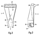
- the bracket 1 is again designed to be fitted onto a projecting arm of a rotary clothes line and provided with a pair of resilient legs 2a, 2b which define a channel 3 to house the supporting arm (not shown).
- the channel 3 is so shaped as to receive selectively a rectangular cross-section arm or a circular cross-section arm and to have a substantial surface area to grip the arm, whichever shape the arm is.
- the channel 3 in a section taken upwardly from the mouth includes a circular portion 3a for closely receiving a clothes line arm of substantially circular cross-section followed by a rectangular portion 3b for closely receiving a clothes line arm of substantially rectangular cross-section.
- each of the legs 2a, 2b is provided with a cut-out 24 which has a diverging mouth and, inwardly of the mouth, a portion that grippingly embraces more than 180° around a transverse member in the form of a fastening bolt 25 which is positioned with the bolt 25 extending through the cut-outs 24.
- a fastening bolt 25 By tightening a nut on the bolt, the bracket 1 can be tightened onto the supporting arm. This gives a sufficiently secure fastening for normal conditions of use.
- the bracket 1 includes a recess 26 at the end remote from the supporting arm and at the side of the bracket remote from the cut-outs 24.
- This recess 26 has lips 27 that can hold a supporting elongate member (not shown) in the form of a rod or stay for the cover for the rotary clothes line.
- the lips 27 ensure that the recess grippingly embraces more than 180° of that rod or stay.
- Alternative arrangements for gripping the rod or stay are possible.
- the bracket 3 could be provided with a groove on its top for receiving the rod or stay with clips that then can be closed to encircle totally the rod or stay.
- the bracket 3 could simply have a hole through it that the rod or stay could be threaded through.
- the cut-out 24 is so shaped with its diverging mouth that, as the bracket 1 breaks free from the bolt 25, the body of the bracket 1 does not restrain the bolt from being released.
- the cut-out 24 is shown as extending in a generally downwards direction; alternatively it could be so shaped that the cut-out 24 extends generally backwards i.e. to the left in Figure 3.
- the cut-out 24 has a generally curved shape, so designed to follow the path that the bolt 25 would make when it breaks free from the body of the bracket 1, thereby not blocking the path of the bolt 25 when it is ejected.
- the generally curved shape of the cut-out 24 extends around an axis of turning of the bracket 1 relative to the arm under the force exerted by the cover on the bracket 3 during extremely windy conditions.
- the channel 3 is designed to receive the largest cross-section of arm that is commercially available. Either of inserts 30 and 31 can be fitted into the channel 3 in order to allow the bracket to be fitted to an arm of a smaller rectangular or circular cross-section.
- the external shape and size of the insert 30 or 31 is of the same shape and size as the channel 3.
- the bracket 1 is provided with a bolt 25 and wing-nut 33 that can be tightened to retain any insert in place in the bracket 1 and on the arm.
Landscapes
- Engineering & Computer Science (AREA)
- Textile Engineering (AREA)
- Clamps And Clips (AREA)
- Holders For Apparel And Elements Relating To Apparel (AREA)
Applications Claiming Priority (4)
| Application Number | Priority Date | Filing Date | Title |
|---|---|---|---|
| GB9904884 | 1999-03-04 | ||
| GBGB9904884.5A GB9904884D0 (en) | 1999-03-04 | 1999-03-04 | Apparatus |
| GBGB9915494.0A GB9915494D0 (en) | 1999-07-03 | 1999-07-03 | Apparatus |
| GB9915494 | 1999-07-05 |
Publications (2)
| Publication Number | Publication Date |
|---|---|
| EP1033430A2 true EP1033430A2 (de) | 2000-09-06 |
| EP1033430A3 EP1033430A3 (de) | 2003-03-26 |
Family
ID=26315211
Family Applications (1)
| Application Number | Title | Priority Date | Filing Date |
|---|---|---|---|
| EP00301817A Withdrawn EP1033430A3 (de) | 1999-03-04 | 2000-03-06 | Halterung für eine Wäscheständerabdeckung |
Country Status (1)
| Country | Link |
|---|---|
| EP (1) | EP1033430A3 (de) |
Cited By (2)
| Publication number | Priority date | Publication date | Assignee | Title |
|---|---|---|---|---|
| GB2466894A (en) * | 2005-01-11 | 2010-07-14 | Parker Hannifin Plc | Connection module and connector |
| WO2013076449A2 (en) | 2011-11-24 | 2013-05-30 | Holland Thomas Seaward | Improvements in or relating to covers and bracket assemblies |
Family Cites Families (5)
| Publication number | Priority date | Publication date | Assignee | Title |
|---|---|---|---|---|
| US2805877A (en) * | 1953-06-12 | 1957-09-10 | Cecil W Ashley | Tool bar hitching clamp |
| US3141221A (en) * | 1962-11-13 | 1964-07-21 | Amtec Inc | Closure for flexible bags |
| DE3365540D1 (en) * | 1982-04-22 | 1986-10-02 | Kuettenbaum Valentin | Joining device for the detachable joining of two construction elements |
| NL8203850A (nl) * | 1982-10-04 | 1984-05-01 | Gustaaf Van Lenthe | Overkapping voor een droogmolen. |
| WO1995001476A2 (en) * | 1993-06-26 | 1995-01-12 | Dorchester House (Home & Garden) Limited | Fixation means and products using a flexible sheet |
-
2000
- 2000-03-06 EP EP00301817A patent/EP1033430A3/de not_active Withdrawn
Cited By (5)
| Publication number | Priority date | Publication date | Assignee | Title |
|---|---|---|---|---|
| GB2466894A (en) * | 2005-01-11 | 2010-07-14 | Parker Hannifin Plc | Connection module and connector |
| GB2421992B (en) * | 2005-01-11 | 2010-08-04 | Parker Hannifin Plc | Connection module and connector |
| GB2466894B (en) * | 2005-01-11 | 2010-08-25 | Parker Hannifin Plc | Connection module and connector |
| WO2013076449A2 (en) | 2011-11-24 | 2013-05-30 | Holland Thomas Seaward | Improvements in or relating to covers and bracket assemblies |
| WO2013076449A3 (en) * | 2011-11-24 | 2013-12-05 | Holland Thomas Seaward | Improvements in or relating to covers and bracket assemblies |
Also Published As
| Publication number | Publication date |
|---|---|
| EP1033430A3 (de) | 2003-03-26 |
Similar Documents
| Publication | Publication Date | Title |
|---|---|---|
| EP3619100B1 (de) | Montagesystem für fahrradgepäckträger | |
| US6793595B1 (en) | Cord fastener for sports nets | |
| US6416109B1 (en) | Canopy rain cover for a golf cart | |
| US20080128163A1 (en) | Hot-stick capable cutout cover | |
| US7913965B2 (en) | Clamp assembly | |
| US6663161B1 (en) | Canopy rain cover for a golf cart | |
| JP3643519B2 (ja) | クランプ式のクロス・バーを備えた車輛用物品キャリヤ | |
| US5664287A (en) | Handle attachment for round door knobs | |
| KR101221431B1 (ko) | 비닐하우스용 고정밴드의 고정수단 | |
| EP1033430A2 (de) | Halterung für eine Wäscheständerabdeckung | |
| BR202019006053U2 (pt) | Travamento de segurança de linha | |
| US4543972A (en) | Lockable tent stake | |
| US6615686B1 (en) | Bike stem clamping device | |
| CN210350740U (zh) | 悬垂线夹 | |
| JPH09331618A (ja) | 送電線把持クランプ | |
| US20110157902A1 (en) | Cover | |
| JPH08127374A (ja) | 自転車用頭上具 | |
| JP7496097B1 (ja) | カーテン取付具、カーテン取付具が設けられる車両及びカーテン | |
| CN218454618U (zh) | 一种可收纳调节天幕 | |
| KR0121972Y1 (ko) | 케이블고정구 | |
| US20060049320A1 (en) | Anti slip device for monitor | |
| JPH0644975Y2 (ja) | 軒樋カバー取付け装置 | |
| JP2553708Y2 (ja) | 樋吊り金具 | |
| CA1172231A (en) | Pipe hanger | |
| KR0166515B1 (ko) | 루프 인슐레이션에 착탈되는 옷걸이 |
Legal Events
| Date | Code | Title | Description |
|---|---|---|---|
| PUAI | Public reference made under article 153(3) epc to a published international application that has entered the european phase |
Free format text: ORIGINAL CODE: 0009012 |
|
| AK | Designated contracting states |
Kind code of ref document: A2 Designated state(s): AT BE CH CY DE DK ES FI FR GB GR IE IT LI LU MC NL PT SE |
|
| AX | Request for extension of the european patent |
Free format text: AL;LT;LV;MK;RO;SI |
|
| PUAL | Search report despatched |
Free format text: ORIGINAL CODE: 0009013 |
|
| AK | Designated contracting states |
Kind code of ref document: A3 Designated state(s): AT BE CH CY DE DK ES FI FR GB GR IE IT LI LU MC NL PT SE Designated state(s): AT BE CH CY DE DK ES FI FR GB GR IE IT LI LU MC NL PT SE |
|
| AX | Request for extension of the european patent |
Extension state: AL LT LV MK RO SI |
|
| RIC1 | Information provided on ipc code assigned before grant |
Ipc: 7F 16B 2/06 B Ipc: 7F 16B 2/10 B Ipc: 7F 16B 5/06 B Ipc: 7F 16B 2/00 B Ipc: 7D 06F 57/04 A |
|
| STAA | Information on the status of an ep patent application or granted ep patent |
Free format text: STATUS: THE APPLICATION IS DEEMED TO BE WITHDRAWN |
|
| 18D | Application deemed to be withdrawn |
Effective date: 20021001 |