EP1033498A2 - Procédé pour la commande d'un cylindre de positionnement à course longue - Google Patents
Procédé pour la commande d'un cylindre de positionnement à course longue Download PDFInfo
- Publication number
- EP1033498A2 EP1033498A2 EP00890038A EP00890038A EP1033498A2 EP 1033498 A2 EP1033498 A2 EP 1033498A2 EP 00890038 A EP00890038 A EP 00890038A EP 00890038 A EP00890038 A EP 00890038A EP 1033498 A2 EP1033498 A2 EP 1033498A2
- Authority
- EP
- European Patent Office
- Prior art keywords
- piston
- pressure
- working position
- pistons
- hydraulic
- Prior art date
- Legal status (The legal status is an assumption and is not a legal conclusion. Google has not performed a legal analysis and makes no representation as to the accuracy of the status listed.)
- Granted
Links
- 238000000034 method Methods 0.000 title claims abstract description 9
- 230000006835 compression Effects 0.000 claims description 8
- 238000007906 compression Methods 0.000 claims description 8
- 230000007423 decrease Effects 0.000 claims description 4
- 230000035939 shock Effects 0.000 abstract description 13
- 230000001419 dependent effect Effects 0.000 abstract description 5
- 238000006073 displacement reaction Methods 0.000 description 21
- 239000012530 fluid Substances 0.000 description 12
- 238000005096 rolling process Methods 0.000 description 5
- 238000010079 rubber tapping Methods 0.000 description 2
- 230000001934 delay Effects 0.000 description 1
- 238000010586 diagram Methods 0.000 description 1
Images

Classifications
-
- F—MECHANICAL ENGINEERING; LIGHTING; HEATING; WEAPONS; BLASTING
- F15—FLUID-PRESSURE ACTUATORS; HYDRAULICS OR PNEUMATICS IN GENERAL
- F15B—SYSTEMS ACTING BY MEANS OF FLUIDS IN GENERAL; FLUID-PRESSURE ACTUATORS, e.g. SERVOMOTORS; DETAILS OF FLUID-PRESSURE SYSTEMS, NOT OTHERWISE PROVIDED FOR
- F15B15/00—Fluid-actuated devices for displacing a member from one position to another; Gearing associated therewith
- F15B15/20—Other details, e.g. assembly with regulating devices
- F15B15/26—Locking mechanisms
-
- B—PERFORMING OPERATIONS; TRANSPORTING
- B21—MECHANICAL METAL-WORKING WITHOUT ESSENTIALLY REMOVING MATERIAL; PUNCHING METAL
- B21B—ROLLING OF METAL
- B21B31/00—Rolling stand structures; Mounting, adjusting, or interchanging rolls, roll mountings, or stand frames
- B21B31/16—Adjusting or positioning rolls
- B21B31/20—Adjusting or positioning rolls by moving rolls perpendicularly to roll axis
- B21B31/32—Adjusting or positioning rolls by moving rolls perpendicularly to roll axis by liquid pressure, e.g. hydromechanical adjusting
-
- B—PERFORMING OPERATIONS; TRANSPORTING
- B21—MECHANICAL METAL-WORKING WITHOUT ESSENTIALLY REMOVING MATERIAL; PUNCHING METAL
- B21B—ROLLING OF METAL
- B21B37/00—Control devices or methods specially adapted for metal-rolling mills or the work produced thereby
- B21B37/58—Roll-force control; Roll-gap control
- B21B37/62—Roll-force control; Roll-gap control by control of a hydraulic adjusting device
-
- B—PERFORMING OPERATIONS; TRANSPORTING
- B21—MECHANICAL METAL-WORKING WITHOUT ESSENTIALLY REMOVING MATERIAL; PUNCHING METAL
- B21B—ROLLING OF METAL
- B21B38/00—Methods or devices for measuring, detecting or monitoring specially adapted for metal-rolling mills, e.g. position detection, inspection of the product
- B21B38/08—Methods or devices for measuring, detecting or monitoring specially adapted for metal-rolling mills, e.g. position detection, inspection of the product for measuring roll-force
-
- B—PERFORMING OPERATIONS; TRANSPORTING
- B21—MECHANICAL METAL-WORKING WITHOUT ESSENTIALLY REMOVING MATERIAL; PUNCHING METAL
- B21B—ROLLING OF METAL
- B21B38/00—Methods or devices for measuring, detecting or monitoring specially adapted for metal-rolling mills, e.g. position detection, inspection of the product
- B21B38/10—Methods or devices for measuring, detecting or monitoring specially adapted for metal-rolling mills, e.g. position detection, inspection of the product for measuring roll-gap, e.g. pass indicators
Definitions
- the invention relates to a method for controlling a long-stroke, hydraulic actuating cylinder, in particular an actuating cylinder for a Compression scaffolding, the one acting on both sides, along its travel path Hydraulically lockable pistons according to his in various working positions Lock is suddenly loaded with an external force.
- the invention is therefore based on the object of a method for Control of a long-stroke, hydraulic actuating cylinder, especially one Setting cylinder for a compression frame of the type described at the beginning that the displacement of the hydraulically locked piston at one shock-like piston loading is limited to a comparatively low level can be.
- the invention solves this problem in that the piston under a hydraulic pressure selected depending on the respective working position is locked over against the direction of action of the external force the travel path decreases.
- the invention is based on the knowledge that in a working position of the piston with a comparatively small cylinder volume on the an external shock load of a discharge side of the piston Hydraulic medium pressure on this piston side because of the comparatively low Volume at a piston displacement is reduced considerably faster than the hydraulic fluid pressure on the opposite side of the piston Range of the larger hydraulic fluid volume increased. Occurs the external shock load of the piston, however, in a working position with a comparatively large cylinder volume on the piston side, which is relieved in the event of a shock load on, so arises in the area of the comparatively low hydraulic medium volume a rapid increase in pressure on the opposite side of the piston on, while the hydraulic fluid pressure in the area of the larger cylinder volume on the other side of the piston is reduced more slowly. This means in a working position with a counter to the direction of impact the end of the stroke displaced a comparatively large piston displacement in the shock load, while this shock-related shift in opposite end of the travel path due to the rapidly building Back pressure remains comparatively small.
- the piston can lock the intended hydraulic pressure already for moving to the respective working position with the one for this working position provided locking pressure are applied so that in In cooperation with the position control, build up a corresponding back pressure must, if the piston is fixed in the respective working position to be held.
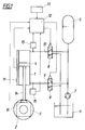
- the roll gap a compression frame with the help of hydraulic actuating cylinders 1, which attack on the chocks 2 for the end storage of the upsetting roller 3.
- the pistons 4 of the actuating cylinder 1 can Pressure accumulator 5 are acted upon on both sides, via a to a hydraulic fluid container 6 connected pump 7 is loaded.
- the application the piston 4 takes place via multi-way valves 8, which in the connecting lines 9 and 10 of the actuating cylinder 1 are switched on.
- valves 8 can be controlled via the control device 12 are controlled so that the pistons 4 assume the respective working position, in which they are hydraulically locked via the valves 8, as in the Fig. 1 is indicated.
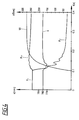
- the locking pressure p v is to increase over the adjustment path s, the lowest locking pressure p v being reached when the piston rod 14 is retracted and the greatest locking pressure p v being reached when the piston rod 14 is extended.
- the travel s is accordingly counted in FIG. 2 from the stop position of the piston 4 for the retracted piston rod 14.
- the hydraulic volume V 1 is greatest on the piston rod side of the piston 4.
- the hydraulic medium volume V 2 on the piston side opposite the piston rod 14 assumes a maximum, while the piston-side hydraulic medium volume V 1 represents a minimum.
- FIGS. 3 and 4 relate like FIG. 2 to an actuating cylinder with a maximum actuation travel of 800 mm.
- 3 shows an average working position of the piston with a travel of 407 mm and a sudden increase in the rolling force W from 0 to 5500 kN
- the locking pressure p v was chosen in accordance with FIG. 2 for the middle working position with 140 bar. From Fig.
- a significantly higher locking pressure of 240 bar can be selected because the pressure on the piston side facing away from the piston rod only rises slightly to approximately 265 bar.
- the pressure p V1 drops sharply, resulting in a slight piston displacement of 1 mm.
- the piston displacements s v are plotted over the travel path s when using the method according to the invention. It follows from this that in the region of the middle working position a largest displacement s v in the region of 2.5 mm is to be expected, while these displacements s v decrease correspondingly towards the end regions. With hydraulic piston locks according to the prior art, piston displacements in the range of ten times these values should be expected.
- the pistons 4 are hydraulically locked under the respectively selected locking pressure p V. It does not need to be particularly emphasized that the selected working position of the pistons 4 can first be approached before the required pressurization pressure p V is set under which the pistons 4 are to be locked. The only thing that matters is that a locking pressure p V which is dependent on the travel s is ensured in order to be able to ensure the maximum counterforce for the abruptly occurring rolling force which is based on the permissible cylinder load.
- Changing conditions in the area of the roll gap can of course also be taken into account via the control device 12.
- the piston action on the compression roller 3 is detected with the help of, for example, a pressure cell 16, so that this application force can be used as a reference variable for the actuating cylinder 1.
- the pistons 4 are locked hydraulically with a locking pressure p V that is dependent on the travel s of the actuating cylinder 1.
Landscapes
- Engineering & Computer Science (AREA)
- Mechanical Engineering (AREA)
- Physics & Mathematics (AREA)
- Fluid Mechanics (AREA)
- General Engineering & Computer Science (AREA)
- Actuator (AREA)
- Fluid-Pressure Circuits (AREA)
- Lifting Devices For Agricultural Implements (AREA)
- Fluid-Damping Devices (AREA)
- Control Of Presses (AREA)
- Vehicle Body Suspensions (AREA)
- Load-Engaging Elements For Cranes (AREA)
- Attitude Control For Articles On Conveyors (AREA)
- Jigs For Machine Tools (AREA)
- Braking Arrangements (AREA)
Priority Applications (2)
| Application Number | Priority Date | Filing Date | Title |
|---|---|---|---|
| AT00890038T ATE278878T1 (de) | 1999-03-01 | 2000-02-15 | Verfahren zur steuerung eines langhubigen hydraulischen stellzylinders |
| SI200030537T SI1033498T1 (en) | 1999-03-01 | 2000-02-15 | Process for controlling a long-stroke positioning cylinder |
Applications Claiming Priority (2)
| Application Number | Priority Date | Filing Date | Title |
|---|---|---|---|
| AT0033299A AT407614B (de) | 1999-03-01 | 1999-03-01 | Verfahren zur steuerung eines langhubigen, hydraulischen stellzylinders |
| AT33299 | 1999-03-01 |
Publications (4)
| Publication Number | Publication Date |
|---|---|
| EP1033498A2 true EP1033498A2 (fr) | 2000-09-06 |
| EP1033498A3 EP1033498A3 (fr) | 2003-02-05 |
| EP1033498A9 EP1033498A9 (fr) | 2003-06-25 |
| EP1033498B1 EP1033498B1 (fr) | 2004-10-06 |
Family
ID=3487789
Family Applications (1)
| Application Number | Title | Priority Date | Filing Date |
|---|---|---|---|
| EP00890038A Expired - Lifetime EP1033498B1 (fr) | 1999-03-01 | 2000-02-15 | Procédé pour la commande d'un cylindre de positionnement à course longue |
Country Status (6)
| Country | Link |
|---|---|
| US (1) | US6443046B1 (fr) |
| EP (1) | EP1033498B1 (fr) |
| AT (2) | AT407614B (fr) |
| DE (1) | DE50008044D1 (fr) |
| ES (1) | ES2228447T3 (fr) |
| SI (1) | SI1033498T1 (fr) |
Cited By (4)
| Publication number | Priority date | Publication date | Assignee | Title |
|---|---|---|---|---|
| WO2005049242A1 (fr) * | 2003-11-19 | 2005-06-02 | Sms Demag Ag | Cylindre de reglage dans des cages de laminoir, notamment dans des cages de refoulement verticales |
| WO2020156932A1 (fr) * | 2019-01-28 | 2020-08-06 | Sms Group Gmbh | Commande de cylindres de réglage hydrauliques dans les cages de laminage |
| WO2021043374A1 (fr) * | 2019-09-05 | 2021-03-11 | Sms Group Gmbh | Unité de laminage transversal et procédé de réglage du passage de rouleau d'une unité de laminage transversal |
| WO2021175636A1 (fr) * | 2020-03-06 | 2021-09-10 | Sms Group Gmbh | Cage de laminage |
Families Citing this family (1)
| Publication number | Priority date | Publication date | Assignee | Title |
|---|---|---|---|---|
| DE102009058977A1 (de) * | 2009-12-18 | 2011-06-22 | Hydac Electronic GmbH, 66128 | Sperreinrichtung |
Family Cites Families (7)
| Publication number | Priority date | Publication date | Assignee | Title |
|---|---|---|---|---|
| GB1163754A (en) * | 1965-12-11 | 1969-09-10 | Gkn Group Services Ltd | Improvements relating to the Rolling of Rod Stock |
| FR1490509A (fr) * | 1966-03-31 | 1967-08-04 | Panhard & Levassor Const Mec | Perfectionnements apportés aux vérins hydrauliques |
| SE440129B (sv) * | 1979-06-20 | 1985-07-15 | Akermans Verkstad Ab | Anordning for att reducera kolvhastigheten i en cylinder, da kolven nermar sig endlegena |
| JPS59183915A (ja) * | 1983-04-01 | 1984-10-19 | Kawasaki Steel Corp | 油圧圧下方式圧延機のロ−ル開度設定方法 |
| CH670777A5 (fr) * | 1986-07-02 | 1989-07-14 | Guenther Alich | |
| US4909060A (en) * | 1988-01-26 | 1990-03-20 | United Engineering, Inc. | Oil compression compensation system |
| DE3939124A1 (de) * | 1989-11-25 | 1991-05-29 | Sundwiger Eisen Maschinen | Vielwalzengeruest mit hydraulischer anstellung |
-
1999
- 1999-03-01 AT AT0033299A patent/AT407614B/de not_active IP Right Cessation
-
2000
- 2000-02-15 ES ES00890038T patent/ES2228447T3/es not_active Expired - Lifetime
- 2000-02-15 DE DE50008044T patent/DE50008044D1/de not_active Expired - Lifetime
- 2000-02-15 AT AT00890038T patent/ATE278878T1/de not_active IP Right Cessation
- 2000-02-15 SI SI200030537T patent/SI1033498T1/xx unknown
- 2000-02-15 EP EP00890038A patent/EP1033498B1/fr not_active Expired - Lifetime
- 2000-02-29 US US09/515,530 patent/US6443046B1/en not_active Expired - Fee Related
Non-Patent Citations (1)
| Title |
|---|
| None |
Cited By (6)
| Publication number | Priority date | Publication date | Assignee | Title |
|---|---|---|---|---|
| WO2005049242A1 (fr) * | 2003-11-19 | 2005-06-02 | Sms Demag Ag | Cylindre de reglage dans des cages de laminoir, notamment dans des cages de refoulement verticales |
| US7631531B2 (en) | 2003-11-19 | 2009-12-15 | Sms Demag Ag | Adjusting roll in rolling frames, among others vertical upset forging frames |
| WO2020156932A1 (fr) * | 2019-01-28 | 2020-08-06 | Sms Group Gmbh | Commande de cylindres de réglage hydrauliques dans les cages de laminage |
| WO2021043374A1 (fr) * | 2019-09-05 | 2021-03-11 | Sms Group Gmbh | Unité de laminage transversal et procédé de réglage du passage de rouleau d'une unité de laminage transversal |
| US12491549B2 (en) | 2019-09-05 | 2025-12-09 | Sms Group Gmbh | Cross-rolling unit and method for setting the roll pass of a cross-rolling unit |
| WO2021175636A1 (fr) * | 2020-03-06 | 2021-09-10 | Sms Group Gmbh | Cage de laminage |
Also Published As
| Publication number | Publication date |
|---|---|
| DE50008044D1 (de) | 2004-11-11 |
| ATE278878T1 (de) | 2004-10-15 |
| ES2228447T3 (es) | 2005-04-16 |
| AT407614B (de) | 2001-05-25 |
| EP1033498A9 (fr) | 2003-06-25 |
| SI1033498T1 (en) | 2005-02-28 |
| ATA33299A (de) | 2000-09-15 |
| EP1033498B1 (fr) | 2004-10-06 |
| EP1033498A3 (fr) | 2003-02-05 |
| US6443046B1 (en) | 2002-09-03 |
Similar Documents
| Publication | Publication Date | Title |
|---|---|---|
| EP1915538B1 (fr) | Montage pour commander un cylindre d'entrainement hydraulique a double effet | |
| EP2772373B1 (fr) | Distributeur proportionnel, circuit hydraulique et système de suspension hydropneumatique doté d'un tel distributeur | |
| DE69227925T2 (de) | Hydraulische pfahlramme | |
| EP3027403B1 (fr) | Presse | |
| WO1992020921A1 (fr) | Dispositif de protection contre les surcharges pour un moteur d'entrainement, se presentant sous la forme d'un moteur a combustion interne, d'une pompe principale d'une unite hydraulique d'alimentation en pression | |
| DE2343832A1 (de) | Lasterfassungs- und druckbegrenzungsorgan mit beschleunigter ausloesung | |
| DE3638574A1 (de) | Anordnung zur drucksteuerung eines daempfungszylinders fuer die abfederung von fahrzeugen | |
| EP0402390B1 (fr) | Agencement de commande de pompes a double cylindre pour liquides epais | |
| EP1033498B1 (fr) | Procédé pour la commande d'un cylindre de positionnement à course longue | |
| EP0719947B1 (fr) | Circuit de détection de charge | |
| EP2157320B1 (fr) | Commande hydraulique pour un moteur hydraulique | |
| DE2436005A1 (de) | Hydraulischer teleskopartiger stossdaempfer | |
| AT412113B (de) | Hyraulische betätigungsanordnung | |
| DE9404736U1 (de) | Vorrichtung zur Steuerung zweier Linearmotoren, insbesondere Hydraulikzylinder | |
| EP0114170A1 (fr) | Protecteur de surcharge pour presses | |
| EP0735275A2 (fr) | Dispositif à crans | |
| DE102006012173A1 (de) | Fahrwerksystem | |
| DE2331697C2 (de) | Aufsetzstoßdämpfer-Einrichtung für Pressenstössel | |
| EP3895884A1 (fr) | Entraînement linéaire hydraulique | |
| DE102006003660B4 (de) | Einrichtung zur Sicherung der Bewegungsreihenfolge von mindestens zwei fluidbetätigten Verdrängereinheiten | |
| DE2503143C2 (de) | Ölhydraulischer Pressenantrieb für eine schnell arbeitende Presse für die Warmverformung von Metallen | |
| EP1295042B1 (fr) | Dispositif de levage | |
| DE3801007A1 (de) | Eilgangschaltung fuer einen schubzylinder, insbesondere fuer einen schubzylinder eines ladekranes | |
| DE102022208236A1 (de) | Walzwerk, insbesondere Kaltpilgerwalzgerüst, Überlastsicherung an einem Walzwerk sowie Verfahren zur Bereitstellung einer Überlastsicherung an einem Walzgerüst | |
| DE2537715B2 (de) | Druckminderventilanordnung und -ausbildung für die Verbindung der beiden Druckräume eines zweistufigen teleskopischen Grubenstempels |
Legal Events
| Date | Code | Title | Description |
|---|---|---|---|
| PUAI | Public reference made under article 153(3) epc to a published international application that has entered the european phase |
Free format text: ORIGINAL CODE: 0009012 |
|
| AK | Designated contracting states |
Kind code of ref document: A2 Designated state(s): AT BE CH CY DE DK ES FI FR GB GR IE IT LI LU MC NL PT SE |
|
| AX | Request for extension of the european patent |
Free format text: AL;LT;LV;MK;RO;SI |
|
| PUAL | Search report despatched |
Free format text: ORIGINAL CODE: 0009013 |
|
| AK | Designated contracting states |
Designated state(s): AT BE CH CY DE DK ES FI FR GB GR IE IT LI LU MC NL PT SE |
|
| AX | Request for extension of the european patent |
Extension state: AL LT LV MK RO SI |
|
| RIC1 | Information provided on ipc code assigned before grant |
Ipc: 7B 21B 37/62 B Ipc: 7B 21B 31/32 B Ipc: 7F 15B 15/26 A |
|
| RIN1 | Information on inventor provided before grant (corrected) |
Inventor name: DEININGER, FRIEDRICH DIPL.-ING. |
|
| RIN1 | Information on inventor provided before grant (corrected) |
Inventor name: DEININGER, FRIEDRICH DIPL.-ING. Inventor name: OBERHUMER, JOHANN Inventor name: RAB, WERNER DIPL.-ING. |
|
| 17P | Request for examination filed |
Effective date: 20030730 |
|
| AKX | Designation fees paid |
Designated state(s): AT BE CH CY DE DK ES FI FR GB GR IE IT LI LU MC NL PT SE |
|
| AXX | Extension fees paid |
Extension state: RO Payment date: 20030730 Extension state: SI Payment date: 20030730 |
|
| GRAP | Despatch of communication of intention to grant a patent |
Free format text: ORIGINAL CODE: EPIDOSNIGR1 |
|
| GRAS | Grant fee paid |
Free format text: ORIGINAL CODE: EPIDOSNIGR3 |
|
| GRAA | (expected) grant |
Free format text: ORIGINAL CODE: 0009210 |
|
| AK | Designated contracting states |
Kind code of ref document: B1 Designated state(s): AT BE CH CY DE DK ES FI FR GB GR IE IT LI LU MC NL PT SE |
|
| AX | Request for extension of the european patent |
Extension state: RO SI |
|
| PG25 | Lapsed in a contracting state [announced via postgrant information from national office to epo] |
Ref country code: IE Free format text: LAPSE BECAUSE OF FAILURE TO SUBMIT A TRANSLATION OF THE DESCRIPTION OR TO PAY THE FEE WITHIN THE PRESCRIBED TIME-LIMIT Effective date: 20041006 |
|
| REG | Reference to a national code |
Ref country code: GB Ref legal event code: FG4D Free format text: NOT ENGLISH |
|
| REG | Reference to a national code |
Ref country code: CH Ref legal event code: EP |
|
| REG | Reference to a national code |
Ref country code: IE Ref legal event code: FG4D Free format text: GERMAN |
|
| REF | Corresponds to: |
Ref document number: 50008044 Country of ref document: DE Date of ref document: 20041111 Kind code of ref document: P |
|
| PG25 | Lapsed in a contracting state [announced via postgrant information from national office to epo] |
Ref country code: GR Free format text: LAPSE BECAUSE OF FAILURE TO SUBMIT A TRANSLATION OF THE DESCRIPTION OR TO PAY THE FEE WITHIN THE PRESCRIBED TIME-LIMIT Effective date: 20050106 Ref country code: DK Free format text: LAPSE BECAUSE OF FAILURE TO SUBMIT A TRANSLATION OF THE DESCRIPTION OR TO PAY THE FEE WITHIN THE PRESCRIBED TIME-LIMIT Effective date: 20050106 |
|
| GBT | Gb: translation of ep patent filed (gb section 77(6)(a)/1977) | ||
| PG25 | Lapsed in a contracting state [announced via postgrant information from national office to epo] |
Ref country code: AT Free format text: LAPSE BECAUSE OF NON-PAYMENT OF DUE FEES Effective date: 20050215 Ref country code: CY Free format text: LAPSE BECAUSE OF FAILURE TO SUBMIT A TRANSLATION OF THE DESCRIPTION OR TO PAY THE FEE WITHIN THE PRESCRIBED TIME-LIMIT Effective date: 20050215 Ref country code: LU Free format text: LAPSE BECAUSE OF NON-PAYMENT OF DUE FEES Effective date: 20050215 |
|
| PG25 | Lapsed in a contracting state [announced via postgrant information from national office to epo] |
Ref country code: LI Free format text: LAPSE BECAUSE OF NON-PAYMENT OF DUE FEES Effective date: 20050228 Ref country code: MC Free format text: LAPSE BECAUSE OF NON-PAYMENT OF DUE FEES Effective date: 20050228 Ref country code: CH Free format text: LAPSE BECAUSE OF NON-PAYMENT OF DUE FEES Effective date: 20050228 |
|
| REG | Reference to a national code |
Ref country code: ES Ref legal event code: FG2A Ref document number: 2228447 Country of ref document: ES Kind code of ref document: T3 |
|
| REG | Reference to a national code |
Ref country code: IE Ref legal event code: FD4D |
|
| ET | Fr: translation filed | ||
| PLBE | No opposition filed within time limit |
Free format text: ORIGINAL CODE: 0009261 |
|
| STAA | Information on the status of an ep patent application or granted ep patent |
Free format text: STATUS: NO OPPOSITION FILED WITHIN TIME LIMIT |
|
| 26N | No opposition filed |
Effective date: 20050707 |
|
| REG | Reference to a national code |
Ref country code: CH Ref legal event code: PL |
|
| PG25 | Lapsed in a contracting state [announced via postgrant information from national office to epo] |
Ref country code: PT Free format text: LAPSE BECAUSE OF NON-PAYMENT OF DUE FEES Effective date: 20050306 |
|
| PGRI | Patent reinstated in contracting state [announced from national office to epo] |
Ref country code: IT Effective date: 20110501 |
|
| PG25 | Lapsed in a contracting state [announced via postgrant information from national office to epo] |
Ref country code: IT Free format text: LAPSE BECAUSE OF NON-PAYMENT OF DUE FEES Effective date: 20110215 |
|
| PGFP | Annual fee paid to national office [announced via postgrant information from national office to epo] |
Ref country code: IT Payment date: 20120222 Year of fee payment: 13 |
|
| PGFP | Annual fee paid to national office [announced via postgrant information from national office to epo] |
Ref country code: SE Payment date: 20130211 Year of fee payment: 14 Ref country code: FR Payment date: 20130301 Year of fee payment: 14 Ref country code: FI Payment date: 20130213 Year of fee payment: 14 Ref country code: ES Payment date: 20130319 Year of fee payment: 14 Ref country code: GB Payment date: 20130213 Year of fee payment: 14 |
|
| PGFP | Annual fee paid to national office [announced via postgrant information from national office to epo] |
Ref country code: NL Payment date: 20130204 Year of fee payment: 14 |
|
| PGFP | Annual fee paid to national office [announced via postgrant information from national office to epo] |
Ref country code: DE Payment date: 20130419 Year of fee payment: 14 Ref country code: BE Payment date: 20130312 Year of fee payment: 14 |
|
| BERE | Be: lapsed |
Owner name: *VOEST-ALPINE INDUSTRIEANLAGENBAU G.M.B.H. Effective date: 20140228 |
|
| REG | Reference to a national code |
Ref country code: DE Ref legal event code: R119 Ref document number: 50008044 Country of ref document: DE |
|
| REG | Reference to a national code |
Ref country code: NL Ref legal event code: V1 Effective date: 20140901 |
|
| REG | Reference to a national code |
Ref country code: SE Ref legal event code: EUG |
|
| GBPC | Gb: european patent ceased through non-payment of renewal fee |
Effective date: 20140215 |
|
| PG25 | Lapsed in a contracting state [announced via postgrant information from national office to epo] |
Ref country code: FI Free format text: LAPSE BECAUSE OF NON-PAYMENT OF DUE FEES Effective date: 20140215 Ref country code: NL Free format text: LAPSE BECAUSE OF NON-PAYMENT OF DUE FEES Effective date: 20140901 |
|
| REG | Reference to a national code |
Ref country code: FR Ref legal event code: ST Effective date: 20141031 |
|
| REG | Reference to a national code |
Ref country code: DE Ref legal event code: R119 Ref document number: 50008044 Country of ref document: DE Effective date: 20140902 |
|
| PG25 | Lapsed in a contracting state [announced via postgrant information from national office to epo] |
Ref country code: SE Free format text: LAPSE BECAUSE OF NON-PAYMENT OF DUE FEES Effective date: 20140216 |
|
| REG | Reference to a national code |
Ref country code: SI Ref legal event code: KO00 Effective date: 20141008 |
|
| PG25 | Lapsed in a contracting state [announced via postgrant information from national office to epo] |
Ref country code: GB Free format text: LAPSE BECAUSE OF NON-PAYMENT OF DUE FEES Effective date: 20140215 Ref country code: FR Free format text: LAPSE BECAUSE OF NON-PAYMENT OF DUE FEES Effective date: 20140228 Ref country code: BE Free format text: LAPSE BECAUSE OF NON-PAYMENT OF DUE FEES Effective date: 20140228 Ref country code: DE Free format text: LAPSE BECAUSE OF NON-PAYMENT OF DUE FEES Effective date: 20140902 |
|
| REG | Reference to a national code |
Ref country code: ES Ref legal event code: FD2A Effective date: 20150505 |
|
| PG25 | Lapsed in a contracting state [announced via postgrant information from national office to epo] |
Ref country code: ES Free format text: LAPSE BECAUSE OF NON-PAYMENT OF DUE FEES Effective date: 20140216 |
|
| PG25 | Lapsed in a contracting state [announced via postgrant information from national office to epo] |
Ref country code: IT Free format text: LAPSE BECAUSE OF NON-PAYMENT OF DUE FEES Effective date: 20140215 |