EP1033520B2 - Raccord à emboîtement détachable pour la connexion de tuyaux - Google Patents
Raccord à emboîtement détachable pour la connexion de tuyaux Download PDFInfo
- Publication number
- EP1033520B2 EP1033520B2 EP00100355A EP00100355A EP1033520B2 EP 1033520 B2 EP1033520 B2 EP 1033520B2 EP 00100355 A EP00100355 A EP 00100355A EP 00100355 A EP00100355 A EP 00100355A EP 1033520 B2 EP1033520 B2 EP 1033520B2
- Authority
- EP
- European Patent Office
- Prior art keywords
- outer part
- plug
- recess
- insertion pin
- connector according
- Prior art date
- Legal status (The legal status is an assumption and is not a legal conclusion. Google has not performed a legal analysis and makes no representation as to the accuracy of the status listed.)
- Expired - Lifetime
Links
- 238000003780 insertion Methods 0.000 claims description 66
- 230000037431 insertion Effects 0.000 claims description 66
- 238000007789 sealing Methods 0.000 claims description 19
- 230000005489 elastic deformation Effects 0.000 claims description 5
- 238000011144 upstream manufacturing Methods 0.000 claims 1
- 230000004323 axial length Effects 0.000 description 4
- 239000002184 metal Substances 0.000 description 3
- 238000000034 method Methods 0.000 description 2
- 238000000926 separation method Methods 0.000 description 2
- 229910000639 Spring steel Inorganic materials 0.000 description 1
- 208000027418 Wounds and injury Diseases 0.000 description 1
- 239000011324 bead Substances 0.000 description 1
- 230000006835 compression Effects 0.000 description 1
- 238000007906 compression Methods 0.000 description 1
- 230000007797 corrosion Effects 0.000 description 1
- 238000005260 corrosion Methods 0.000 description 1
- 230000008878 coupling Effects 0.000 description 1
- 238000010168 coupling process Methods 0.000 description 1
- 238000005859 coupling reaction Methods 0.000 description 1
- 230000006378 damage Effects 0.000 description 1
- 238000006073 displacement reaction Methods 0.000 description 1
- 239000012530 fluid Substances 0.000 description 1
- 238000002347 injection Methods 0.000 description 1
- 239000007924 injection Substances 0.000 description 1
- 208000014674 injury Diseases 0.000 description 1
- 238000004519 manufacturing process Methods 0.000 description 1
- 230000013011 mating Effects 0.000 description 1
- 210000000056 organ Anatomy 0.000 description 1
Images


Classifications
-
- F—MECHANICAL ENGINEERING; LIGHTING; HEATING; WEAPONS; BLASTING
- F16—ENGINEERING ELEMENTS AND UNITS; GENERAL MEASURES FOR PRODUCING AND MAINTAINING EFFECTIVE FUNCTIONING OF MACHINES OR INSTALLATIONS; THERMAL INSULATION IN GENERAL
- F16L—PIPES; JOINTS OR FITTINGS FOR PIPES; SUPPORTS FOR PIPES, CABLES OR PROTECTIVE TUBING; MEANS FOR THERMAL INSULATION IN GENERAL
- F16L37/00—Couplings of the quick-acting type
- F16L37/08—Couplings of the quick-acting type in which the connection between abutting or axially overlapping ends is maintained by locking members
- F16L37/084—Couplings of the quick-acting type in which the connection between abutting or axially overlapping ends is maintained by locking members combined with automatic locking
- F16L37/088—Couplings of the quick-acting type in which the connection between abutting or axially overlapping ends is maintained by locking members combined with automatic locking by means of a split elastic ring
-
- F—MECHANICAL ENGINEERING; LIGHTING; HEATING; WEAPONS; BLASTING
- F16—ENGINEERING ELEMENTS AND UNITS; GENERAL MEASURES FOR PRODUCING AND MAINTAINING EFFECTIVE FUNCTIONING OF MACHINES OR INSTALLATIONS; THERMAL INSULATION IN GENERAL
- F16L—PIPES; JOINTS OR FITTINGS FOR PIPES; SUPPORTS FOR PIPES, CABLES OR PROTECTIVE TUBING; MEANS FOR THERMAL INSULATION IN GENERAL
- F16L37/00—Couplings of the quick-acting type
- F16L37/08—Couplings of the quick-acting type in which the connection between abutting or axially overlapping ends is maintained by locking members
- F16L37/084—Couplings of the quick-acting type in which the connection between abutting or axially overlapping ends is maintained by locking members combined with automatic locking
Definitions
- the elastic seal arranged so that it can not be removed in the locking position of the plug pin from the outside, so far it must be designed elastically deformable and optionally axially displaceable, that the plug pin is movable by overcoming the axial force in the release position.
- the elastic seal In the release position, the elastic seal is supported on a cylindrical or undercut surface in the outer part such that the plug-in pin is held frictionally or positively. As a result, the removal of the retaining element is facilitated.
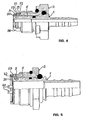
- FIG. 6 shows the connector in the locked position in which the plug pin 5 is effectively sealed by the sealing ring 6 in the bore 15 and in which the sealing ring 7 the plug pin 5 in the axial direction with the side surface 10 against the support member 3 and this in turn against the side surface 24th the recess 23 presses.
- the holding element 3 is in this case with its cylindrical surface on the portion 35 of the bore surface of the recess 23 at. An elastic deformation of the holding element 3 radially inwardly counteracts the conical surface 12.
- the axial distance between the outer part 2 and the stop element 40 is significantly smaller than the axial length of the recess 23. This ensures that in the stop position of the stop element 40, the holding element 3 is still within the recess 23.
- the retaining element 3 snaps into the recess 18 in the movement of the plug pin 5 against the plugging direction, the retaining element 3 protruding from the side surface 19 of the recess 18 in the outer part 2 is held.
- the sealing rings 6 and 7 are no longer effective and pressure medium can escape through a gap between the plug pin 5 and the outer part 2 and thereby audibly or visibly indicate the faulty plugging operation.
Landscapes
- Engineering & Computer Science (AREA)
- General Engineering & Computer Science (AREA)
- Mechanical Engineering (AREA)
- Quick-Acting Or Multi-Walled Pipe Joints (AREA)
Claims (15)
- Raccord par emboîtement pour le raccord de tuyaux de canalisation, avec une partie intérieure (1) et une partie extérieure (2) qui peuvent être reliées entre elles et séparées l'une de l'autre, la partie extérieure (2) étant fixée de façon réversible dans un trou d'une pièce de boîtier et la partie intérieure (1) pouvant être enfichée par un tenon de raccordement (5) dans une ouverture de la partie extérieure (2) et pouvant y être verrouillée au moyen d'un élément de retenue (3) déformable élastiquement en direction radiale, lequel élément de retenue est disposé dans un évidement (8) pratiqué dans l'enveloppe du tenon de raccordement (5) et peut être repoussé lors du processus d'emboîtement dans cet évidement (8) par déformation élastique radiale et qui en position verrouillée du tenon de raccordement (5) dans la partie extérieure (2) s'engage de telle sorte par retour de déformation élastique dans un évidement (23) pratiqué dans l'ouverture de la partie extérieure (2) que le tenon de raccordement (5) est verrouillé contre l'extraction hors de l'ouverture par l'élément de retenue (3), l'évidement (23) pratiqué dans l'ouverture de la partie extérieure (2) s'étendant jusqu'à la surface de délimitation antérieure, considérée dans la direction d'emboîtement, de la partie extérieure (2), et de telle sorte que le tenon de raccordement (5) avec l'élément de retenue (3) peut être déplacé dans la direction d'emboîtement au-delà de la position de verrouillage jusque dans une position de déverrouillage dans laquelle l'élément de retenue (3) peut-être extrait de l'évidement (8) du tenon de raccordement, caractérisé en ce qu'un second évidement (18) est prévu dans l'ouverture de la partie extérieure (2), considéré dans la direction d'emboîtement devant l'évidement (23) et à distance de celui-ci, dans lequel l'élément de retenue (3) s'engage par retour de déformation élastique avant d'atteindre la position de verrouillage, et de cette manière retient le tenon de raccordement (5) dans la partie extérieure (2), et en ce que dans cette position, le tenon de raccordement (5) n'est pas rendu entièrement étanche dans l'ouverture de la partie extérieure (2) et le deuxième évidement (18) est limité dans la direction d'emboîtement par une surface conique (20) dont le diamètre diminue dans la direction d'emboîtement et est conçu de telle sorte qu'en enfichant plus profondément le tenon de raccordement (5) dans la partie extérieure (2), le tenon de raccordement (5) peut être déplacé avec l'élément de retenue (3) en position de verrouillage dans laquelle le tenon de raccordement (5) est rendu étanche dans l'ouverture de la partie extérieure (2) par un joint annulaire (6), et en ce que l'évidement (23) pratiqué dans l'ouverture de la partie extérieure (2), dans lequel s'engage l'élément de retenue (3) lorsqu'il est en position de verrouillage, est muni d'une surface de centrage (36) s'élargissant en formant un cône dans la direction d'emboîtement.
- Raccord par emboîtement selon la revendication 1, caractérisé en ce qu'un élément de butée (40) est fixé de façon réversible sur la section de la partie intérieure (1) qui en position de verrouillage dépasse de la partie extérieure (2), lequel élément de butée limite un mouvement du tenon de raccordement (5) dans la direction d'emboîtement après que le point de verrouillage a été atteint et avant que la position de déverrouillage ne soit atteinte en s'appuyant contre la partie extérieure (2), et en ce qu'après l'enlèvement de l'élément de butée (40) de la partie extérieure (2) le tenon de raccordement (5) peut être déplacé en position de déverrouillage.
- Raccord par emboîtement selon la revendication 1, caractérisé en ce qu'un élément de butée (25, 28, 31) est fixé de façon réversible sur l'extrémité antérieure, considéré dans la direction d'emboîtement, de la pièce extérieure (2), lequel élément de butée limite le mouvement du tenon de raccordement (5) dans la direction d'emboîtement, et en ce qu'après l'enlèvement de l'élément de butée (25, 28 31) de la partie extérieure (2) le tenon de raccordement (5) avec l'élément de retenue (3) peut être déplacé dans la direction d'emboîtement au-delà de la position de verrouillage dans une position de déverrouillage dans laquelle l'élément de retenue (3) peut être enlevé de l'évidement (23) du tenon de raccordement.
- Raccord par emboîtement selon la revendication 3, caractérisé en ce que l'élément de butée (25) saisit en la recouvrant la face terminale antérieure dans la direction d'emboîtement du tenon de raccordement (5).
- Raccord par emboîtement selon la revendication 3, caractérisé en ce que l'élément de butée (28) en position de verrouillage saisit en la recouvrant l'enveloppe de l'extrémité antérieure du tenon de raccordement (5) et forme une butée pour l'élément de retenue (3).
- Raccord par emboîtement selon la revendication 2 ou 3, caractérisé en ce que l'élément de butée (25, 28, 40) est constitué d'un anneau déformable élastiquement et interrompu par une fente radiale qui recouvre la partie intérieure (1) ou la partie extérieure (2) sur un angle inscrit supérieur à 180°.
- Raccord par emboîtement selon la revendication 6, caractérisé en ce que l'élément de butée (25, 28, 40) s'engage dans une gorge extérieure (22) de la partie extérieure (2) ou de la partie intérieure (1).
- Raccord par emboîtement selon la revendication 2, caractérisé en ce que l'élément de butée (40) recouvre une collerette annulaire (37) formée sur l'enveloppe de la partie intérieure et est muni dans une surface de trou d'une gorge (38) destinée à recevoir la collerette annulaire (37).
- Raccord par emboîtement selon la revendication 3, caractérisé en ce que l'élément de butée (31) est formé par un anneau interrompu par une fente et pouvant être repoussé radialement, qui s'engage dans une gorge intérieure (32) pratiquée dans l'évidement (23) dans la partie extérieure.
- Raccord par emboîtement selon la revendication 1, caractérisé en ce que la partie extérieure (2) est munie sur son extrémité postérieure, considéré par rapport à la direction d'introduction, d'un évidement dans lequel est disposé un joint élastique (7) qui voisine un épaulement de la partie intérieure (1) et, en position de verrouillage du tenon de raccordement (5), exerce sur la partie intérieure (1) une force axiale opposée à la direction d'emboîtement.
- Raccord par emboîtement selon la revendication 10, caractérisé en ce que le joint élastique (7) en position de déverrouillage s'appuie de telle sorte sur le tenon de raccordement (5) et la partie extérieure (2) que le tenon de raccordement (5) est maintenu par le joint (7) en position de déverrouillage par frottement ou par forme.
- Raccord par emboîtement selon les revendications 10 ou 11, caractérisé en ce que le joint élastique (7) forme un élément de butée qui limite un mouvement du tenon de raccordement (5) dans la direction d'emboîtement après que le point de verrouillage a été atteint et avant que la position de déverrouillage ne soit atteinte.
- Raccord par emboîtement selon l'une des revendications précédentes, caractérisé en ce que l'élément de retenue (3) est un anneau circulaire fendu radialement, déformable radialement qui a une section transversale rectangulaire.
- Raccord par emboîtement selon l'une des revendications précédentes, caractérisé en ce que l'évidement (8) pratiqué dans le tenon de raccordement (5) destiné à recevoir l'élément de retenue (3) est constitué d'une gorge extérieure avec des surfaces latérales radiales (10, 11) pour servir d'appui à l'élément de retenue.
- Raccord par emboîtement selon la revendication 14, caractérisé en ce que la surface latérale (10) de l'évidement (8) pratiqué dans le tenon de raccordement (5) contre lequel l'élément de retenue (3) prend appui dans la direction d'emboîtement se poursuit radialement vers l'intérieur par une surface conique (12) se rétrécissant en allant vers le milieu de l'évidement (8).
Applications Claiming Priority (2)
| Application Number | Priority Date | Filing Date | Title |
|---|---|---|---|
| DE19909394A DE19909394B4 (de) | 1998-10-21 | 1999-03-04 | Lösbare Steckverbindung für den Anschluß von Rohrleitungen |
| DE19909394 | 1999-03-04 |
Publications (4)
| Publication Number | Publication Date |
|---|---|
| EP1033520A2 EP1033520A2 (fr) | 2000-09-06 |
| EP1033520A3 EP1033520A3 (fr) | 2002-10-16 |
| EP1033520B1 EP1033520B1 (fr) | 2004-08-18 |
| EP1033520B2 true EP1033520B2 (fr) | 2010-05-26 |
Family
ID=7899612
Family Applications (1)
| Application Number | Title | Priority Date | Filing Date |
|---|---|---|---|
| EP00100355A Expired - Lifetime EP1033520B2 (fr) | 1999-03-04 | 2000-01-07 | Raccord à emboîtement détachable pour la connexion de tuyaux |
Country Status (2)
| Country | Link |
|---|---|
| EP (1) | EP1033520B2 (fr) |
| DE (1) | DE50007422D1 (fr) |
Citations (4)
| Publication number | Priority date | Publication date | Assignee | Title |
|---|---|---|---|---|
| EP0059877B1 (fr) † | 1981-03-07 | 1985-05-08 | Johannes Schäfer vormals Stettiner Schraubenwerke GmbH & Co. KG | Accouplement pour tuyaux à pression |
| WO1988005882A1 (fr) † | 1987-02-03 | 1988-08-11 | Automobiles Peugeot | Raccord a assemblage rapide |
| EP0226689B1 (fr) † | 1984-06-21 | 1991-07-31 | Ab Volvo | Disposition pour raccorder des conduites de fluide sous pression |
| DE29719247U1 (de) † | 1997-10-29 | 1999-02-25 | Armaturenfabrik Hermann Voss GmbH + Co, 51688 Wipperfürth | Steckkupplung für Druckmittelsysteme |
Family Cites Families (6)
| Publication number | Priority date | Publication date | Assignee | Title |
|---|---|---|---|---|
| US4750765A (en) * | 1987-07-27 | 1988-06-14 | Stratoflex, Inc. | Quick-connect coupling |
| DE19523831A1 (de) * | 1995-06-30 | 1997-01-02 | Voss Armaturen | Steckkupplung für Druckmittelsysteme |
| DE19536333A1 (de) * | 1995-09-29 | 1997-04-03 | Voss Armaturen | Steckkupplung für Druckmittelsysteme |
| DE19705167C5 (de) * | 1997-02-11 | 2006-11-02 | Johannes Schäfer vorm. Stettiner Schraubenwerke GmbH & Co. KG | Steckverbindung für Rohrleitungen |
| DE19707371A1 (de) * | 1997-02-25 | 1998-08-27 | Voss Armaturen | Druckmittel-Steckkupplung |
| DE19819758A1 (de) * | 1997-08-19 | 1999-02-25 | Schaefer Stettiner Schrauben | Steckverbindung für Rohrleitungen |
-
2000
- 2000-01-07 EP EP00100355A patent/EP1033520B2/fr not_active Expired - Lifetime
- 2000-01-07 DE DE50007422T patent/DE50007422D1/de not_active Expired - Lifetime
Patent Citations (4)
| Publication number | Priority date | Publication date | Assignee | Title |
|---|---|---|---|---|
| EP0059877B1 (fr) † | 1981-03-07 | 1985-05-08 | Johannes Schäfer vormals Stettiner Schraubenwerke GmbH & Co. KG | Accouplement pour tuyaux à pression |
| EP0226689B1 (fr) † | 1984-06-21 | 1991-07-31 | Ab Volvo | Disposition pour raccorder des conduites de fluide sous pression |
| WO1988005882A1 (fr) † | 1987-02-03 | 1988-08-11 | Automobiles Peugeot | Raccord a assemblage rapide |
| DE29719247U1 (de) † | 1997-10-29 | 1999-02-25 | Armaturenfabrik Hermann Voss GmbH + Co, 51688 Wipperfürth | Steckkupplung für Druckmittelsysteme |
Also Published As
| Publication number | Publication date |
|---|---|
| EP1033520B1 (fr) | 2004-08-18 |
| DE50007422D1 (de) | 2004-09-23 |
| EP1033520A3 (fr) | 2002-10-16 |
| EP1033520A2 (fr) | 2000-09-06 |
Similar Documents
| Publication | Publication Date | Title |
|---|---|---|
| DE102006062894B4 (de) | Schutzkappe | |
| DE69912260T2 (de) | Verbinder für rohrförmige elemente | |
| EP2799751B1 (fr) | Raccord de conduite de fluide | |
| DE69002047T2 (de) | Rohrkupplung. | |
| EP3173675B1 (fr) | Raccord de tuyau | |
| EP0806597A1 (fr) | Raccord rapide | |
| EP1840437A2 (fr) | Dispositif d'étanchéité pour un raccord rapide | |
| DE10261595B4 (de) | Rohrverbinder | |
| EP2479470B1 (fr) | Raccord enfichage pour conduites d'agent sous pression | |
| DE2822259C2 (de) | Schnellkupplung für rohrförmige Leitungen, insbesondere für Flüssigkeiten | |
| DE3923579A1 (de) | Anschlussarmatur fuer rohre, insbesondere fuer kunststoffrohre | |
| DE29621046U1 (de) | Anschlußsteckvorrichtung für Kunststoffrohre | |
| DE102007059329B4 (de) | Steckverbindung für Rohrleitungen | |
| EP0898109B1 (fr) | Raccord emboitable pour tuyaux | |
| WO2019002323A1 (fr) | Manchon de sertissage | |
| DE29610385U1 (de) | Steckkupplung für Rohre | |
| EP1354163B1 (fr) | Dispositif de raccordement desserrable a une extremite d'un conduite tubulaire, en particulier raccord rapide | |
| DE19819758A1 (de) | Steckverbindung für Rohrleitungen | |
| EP3153757B1 (fr) | Raccord déconnectable | |
| DE102005044751A1 (de) | Steckverbinder für Medienleitungen | |
| DE19848489B4 (de) | Lösbare Steckverbindung für den Anschluß von Rohrleitungen | |
| EP1770320A1 (fr) | Raccord détachable à fiche pour des tuyaux | |
| EP1033520B1 (fr) | Raccord à emboítement détachable pour la connexion de tuyaux | |
| DE202006018794U1 (de) | Steckverbindung für Rohrleitungen | |
| EP0751332B1 (fr) | Raccord emboítable pour systèmes sous pression |
Legal Events
| Date | Code | Title | Description |
|---|---|---|---|
| PUAI | Public reference made under article 153(3) epc to a published international application that has entered the european phase |
Free format text: ORIGINAL CODE: 0009012 |
|
| AK | Designated contracting states |
Kind code of ref document: A2 Designated state(s): AT BE CH CY DE DK ES FI FR GB GR IE IT LI LU MC NL PT SE |
|
| AX | Request for extension of the european patent |
Free format text: AL;LT;LV;MK;RO;SI |
|
| PUAL | Search report despatched |
Free format text: ORIGINAL CODE: 0009013 |
|
| AK | Designated contracting states |
Kind code of ref document: A3 Designated state(s): AT BE CH CY DE DK ES FI FR GB GR IE IT LI LU MC NL PT SE |
|
| AX | Request for extension of the european patent |
Free format text: AL;LT;LV;MK;RO;SI |
|
| RIC1 | Information provided on ipc code assigned before grant |
Free format text: 7F 16L 37/02 A, 7F 16L 37/088 B |
|
| 17P | Request for examination filed |
Effective date: 20030405 |
|
| AKX | Designation fees paid |
Designated state(s): DE FR IT NL SE |
|
| 17Q | First examination report despatched |
Effective date: 20030627 |
|
| GRAP | Despatch of communication of intention to grant a patent |
Free format text: ORIGINAL CODE: EPIDOSNIGR1 |
|
| GRAS | Grant fee paid |
Free format text: ORIGINAL CODE: EPIDOSNIGR3 |
|
| GRAA | (expected) grant |
Free format text: ORIGINAL CODE: 0009210 |
|
| AK | Designated contracting states |
Kind code of ref document: B1 Designated state(s): DE FR IT NL SE |
|
| PG25 | Lapsed in a contracting state [announced via postgrant information from national office to epo] |
Ref country code: IT Free format text: LAPSE BECAUSE OF FAILURE TO SUBMIT A TRANSLATION OF THE DESCRIPTION OR TO PAY THE FEE WITHIN THE PRESCRIBED TIME-LIMIT;WARNING: LAPSES OF ITALIAN PATENTS WITH EFFECTIVE DATE BEFORE 2007 MAY HAVE OCCURRED AT ANY TIME BEFORE 2007. THE CORRECT EFFECTIVE DATE MAY BE DIFFERENT FROM THE ONE RECORDED. Effective date: 20040818 Ref country code: NL Free format text: LAPSE BECAUSE OF FAILURE TO SUBMIT A TRANSLATION OF THE DESCRIPTION OR TO PAY THE FEE WITHIN THE PRESCRIBED TIME-LIMIT Effective date: 20040818 Ref country code: FR Free format text: LAPSE BECAUSE OF FAILURE TO SUBMIT A TRANSLATION OF THE DESCRIPTION OR TO PAY THE FEE WITHIN THE PRESCRIBED TIME-LIMIT Effective date: 20040818 |
|
| REG | Reference to a national code |
Ref country code: IE Ref legal event code: FG4D Free format text: GERMAN |
|
| REF | Corresponds to: |
Ref document number: 50007422 Country of ref document: DE Date of ref document: 20040923 Kind code of ref document: P |
|
| PG25 | Lapsed in a contracting state [announced via postgrant information from national office to epo] |
Ref country code: SE Free format text: LAPSE BECAUSE OF FAILURE TO SUBMIT A TRANSLATION OF THE DESCRIPTION OR TO PAY THE FEE WITHIN THE PRESCRIBED TIME-LIMIT Effective date: 20041118 |
|
| NLV1 | Nl: lapsed or annulled due to failure to fulfill the requirements of art. 29p and 29m of the patents act | ||
| REG | Reference to a national code |
Ref country code: IE Ref legal event code: FD4D |
|
| PLAQ | Examination of admissibility of opposition: information related to despatch of communication + time limit deleted |
Free format text: ORIGINAL CODE: EPIDOSDOPE2 |
|
| PLBQ | Unpublished change to opponent data |
Free format text: ORIGINAL CODE: EPIDOS OPPO |
|
| PLBI | Opposition filed |
Free format text: ORIGINAL CODE: 0009260 |
|
| PLAQ | Examination of admissibility of opposition: information related to despatch of communication + time limit deleted |
Free format text: ORIGINAL CODE: EPIDOSDOPE2 |
|
| PLAR | Examination of admissibility of opposition: information related to receipt of reply deleted |
Free format text: ORIGINAL CODE: EPIDOSDOPE4 |
|
| PLBQ | Unpublished change to opponent data |
Free format text: ORIGINAL CODE: EPIDOS OPPO |
|
| PLAB | Opposition data, opponent's data or that of the opponent's representative modified |
Free format text: ORIGINAL CODE: 0009299OPPO |
|
| PLAQ | Examination of admissibility of opposition: information related to despatch of communication + time limit deleted |
Free format text: ORIGINAL CODE: EPIDOSDOPE2 |
|
| PLAR | Examination of admissibility of opposition: information related to receipt of reply deleted |
Free format text: ORIGINAL CODE: EPIDOSDOPE4 |
|
| PLAX | Notice of opposition and request to file observation + time limit sent |
Free format text: ORIGINAL CODE: EPIDOSNOBS2 |
|
| PLBQ | Unpublished change to opponent data |
Free format text: ORIGINAL CODE: EPIDOS OPPO |
|
| PLAB | Opposition data, opponent's data or that of the opponent's representative modified |
Free format text: ORIGINAL CODE: 0009299OPPO |
|
| 26 | Opposition filed |
Opponent name: VOSS AUTOMOTIVE GMBH Effective date: 20050517 |
|
| R26 | Opposition filed (corrected) |
Opponent name: VOSS AUTOMOTIVE GMBH Effective date: 20050517 |
|
| R26 | Opposition filed (corrected) |
Opponent name: VOSS AUTOMOTIVE GMBH Effective date: 20050517 |
|
| EN | Fr: translation not filed | ||
| PLBB | Reply of patent proprietor to notice(s) of opposition received |
Free format text: ORIGINAL CODE: EPIDOSNOBS3 |
|
| PLCK | Communication despatched that opposition was rejected |
Free format text: ORIGINAL CODE: EPIDOSNREJ1 |
|
| APBP | Date of receipt of notice of appeal recorded |
Free format text: ORIGINAL CODE: EPIDOSNNOA2O |
|
| APAH | Appeal reference modified |
Free format text: ORIGINAL CODE: EPIDOSCREFNO |
|
| APAH | Appeal reference modified |
Free format text: ORIGINAL CODE: EPIDOSCREFNO |
|
| APBQ | Date of receipt of statement of grounds of appeal recorded |
Free format text: ORIGINAL CODE: EPIDOSNNOA3O |
|
| APBU | Appeal procedure closed |
Free format text: ORIGINAL CODE: EPIDOSNNOA9O |
|
| PUAH | Patent maintained in amended form |
Free format text: ORIGINAL CODE: 0009272 |
|
| STAA | Information on the status of an ep patent application or granted ep patent |
Free format text: STATUS: PATENT MAINTAINED AS AMENDED |
|
| 27A | Patent maintained in amended form |
Effective date: 20100526 |
|
| AK | Designated contracting states |
Kind code of ref document: B2 Designated state(s): DE FR IT NL SE |
|
| PGFP | Annual fee paid to national office [announced via postgrant information from national office to epo] |
Ref country code: DE Payment date: 20190328 Year of fee payment: 20 |
|
| REG | Reference to a national code |
Ref country code: DE Ref legal event code: R071 Ref document number: 50007422 Country of ref document: DE |