EP1033552A2 - Système de positionnement pour véhicules - Google Patents
Système de positionnement pour véhicules Download PDFInfo
- Publication number
- EP1033552A2 EP1033552A2 EP00301707A EP00301707A EP1033552A2 EP 1033552 A2 EP1033552 A2 EP 1033552A2 EP 00301707 A EP00301707 A EP 00301707A EP 00301707 A EP00301707 A EP 00301707A EP 1033552 A2 EP1033552 A2 EP 1033552A2
- Authority
- EP
- European Patent Office
- Prior art keywords
- measuring
- vehicle
- measuring points
- points
- datum line
- Prior art date
- Legal status (The legal status is an assumption and is not a legal conclusion. Google has not performed a legal analysis and makes no representation as to the accuracy of the status listed.)
- Withdrawn
Links
- 238000000034 method Methods 0.000 claims abstract description 17
- 238000005259 measurement Methods 0.000 description 15
- 238000010586 diagram Methods 0.000 description 5
- 230000005540 biological transmission Effects 0.000 description 2
- 230000002159 abnormal effect Effects 0.000 description 1
- 238000012986 modification Methods 0.000 description 1
- 230000004048 modification Effects 0.000 description 1
- 230000011664 signaling Effects 0.000 description 1
Images


Classifications
-
- G—PHYSICS
- G01—MEASURING; TESTING
- G01B—MEASURING LENGTH, THICKNESS OR SIMILAR LINEAR DIMENSIONS; MEASURING ANGLES; MEASURING AREAS; MEASURING IRREGULARITIES OF SURFACES OR CONTOURS
- G01B5/00—Measuring arrangements characterised by the use of mechanical techniques
- G01B5/0025—Measuring of vehicle parts
-
- B—PERFORMING OPERATIONS; TRANSPORTING
- B60—VEHICLES IN GENERAL
- B60S—SERVICING, CLEANING, REPAIRING, SUPPORTING, LIFTING, OR MANOEUVRING OF VEHICLES, NOT OTHERWISE PROVIDED FOR
- B60S5/00—Servicing, maintaining, repairing, or refitting of vehicles
Definitions
- the present invention relates to vehicle positioning and particularly, but not exclusively, to a method of determining the position of a part of a vehicle.
- the present invention seeks to provide an improved method and apparatus for determining the position of a part of a vehicle.
- a method of determining the position of a part of a vehicle comprising measuring the distance from a first measuring location to each of a plurality of measuring points associated with said part, measuring the distance from a second measuring location to each of said measuring points, calculating the position of each of said measuring points relative to a fixed location, and comparing the position of each of said measuring points relative to said fixed location so as to determine the position of said part in said vehicle.
- the step of calculating includes calculating the position of a datum line relative to which the position of the part is to be determined.
- the step of calculating may further include calculating the position of the intersection between the datum line and a line joining a respective measuring point and the datum line and which is perpendicular thereto.
- the step of comparing may include comparing the positional distance along the datum line of the intersections with the datum line of two or more lines extending between the datum line and measuring points associated with a common part.
- a measuring apparatus for locating the position of a part of a vehicle, the apparatus comprising means for defining each of a plurality of measuring points associated with said part, means for measuring the distance from first and second measuring locations on said vehicle to each of said measuring points, means for calculating the position of each of said measuring points relative to a fixed location on the vehicle; and means for comparing the position of each of said measuring points relative to said fixed location so as to determine the position of said part on said vehicle.
- the means for defining said measuring points includes a main body having attachment means at one end thereof for attaching said body to said vehicle, an elongate member extending substantially from said main body and universally pivotably mounted to pivot relative to the main body about a pivot point at a central point of the attachment means, fixing means for releasably fixing the position of the elongate member relative to the main body; and a measuring position located at a predetermined position along the elongate member, wherein the apparatus is arranged such that, in use, the measuring position lies vertically below said central point.
- the elongate member is pivotably mounted by means ofa wire attached at one end to the member and at the other end to said central point.
- the measuring position may comprise a groove or other means in said elongate member for engagement with a part of an associated measuring unit.
- the apparatus may further comprise checking means mounted on said elongate member for checking the verticality thereof.
- the checking means may comprise a spherical spirit level, or an electronic levelling device, preferably mounted for axial rotation about said elongate member.
- a vehicle 10 has parts whose position is to be checked.
- the vehicle is a four-wheel vehicle with rear-wheel drive.
- the vehicle has a front-mounted engine 10, mounted on two laterally extending, substantial ly parallel cross members 12, 14.
- a drive shaft 16 which transmits drive from the engine to a rear wheel drive assembly 18, extends rearwardly from the engine and substantially perpendicularly to the engine cross members 12, 14.
- the rear wheel drive assembly 18 may comprise a rear wheel differential and two opposing prop-shafts (not shown) connected between the differential and a respective rear wheel. Such an arrangement is conventional in a rear wheel drive vehicle.
- a jig is used to position the parts of the vehicle by means of measuring points, known as "pick-up" points, on or associated with those parts.
- the jig has a number of positioning locators corresponding to the pick-up points of the vehicle parts and the parts are positioned by aligning the pick-up points with the positioning locators on the jig.
- the vehicle body is located on the jig by using two datum pick-up points on the body.
- the datum pick-up points are usually located on the left side of the body, one at the front and one at the rear. When located, the engine, transmission and drive units are bolted to the body.
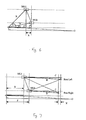
- measuring locations MU1/ MU2 In order to determine the position of the parts of a vehicle, distance measurements are taken between certain measuring locations MU1/ MU2, and pick-up points A - E on or associated with the parts of the vehicle.
- the positions of measuring locations MU1 and MU2 and pick-up points C-E are calculated relative to a datum line 20 defined by pick-up points A and B which constitute the known datum pick-up points which are used in the positioning of the vehicle parts during factory assembly.
- the distance measurements between measurement locations MU1/MU2 and pick-up points A-E are taken using a measuring unit, a preferred form of which is shown in fig. 2.
- the measuring unit 100 has a main body 102, in the form of a substantially rectangular box, rigidly connected to a mounting plate 104 by means of supports 106a, 106b.
- the mounting plate has an aperture at one end thereof through which a bolt or the like can be passed to enable the mounting plate to be rigidly mounted on a vehicle part, in this case a vehicle cross member.
- the main body 102 has an aperture 108 in one side thereof from which extends a flexible measuring wire 110.
- a sleeve 112 extending substantially perpendicularly from the main body 102 surrounds the wire 110 along a portion of its length nearest the aperture 108.
- a measuring hook 114 is secured to the end of the wire.
- the measuring wire 110 is wound round a rotatable spool (not shown) within the main body 102 such that it can be unwound and extended through the aperture by pulling on the wire.
- the spool is spring mounted to retract the wire back onto the spool when the wire is released.
- the measuring unit 100 also includes a sensing unit (not shown) which senses the length of the wire unwound from the spool, and provides a calibrated reading corresponding to that length.
- Each dropper 200 a preferred form of which is shown in fig 3 includes a main body 202, preferably of cylindrical form, having a mounting means in the form of an axially extending thread 204 at an upper end thereof.
- the thread 204 is adapted to be inserted through the bore of the respective pick-up point A - E in the part such that it can be accurately located in the centre of the pick-up point bore and rigidly held in position on the part by means of a nut (fig. 3a).
- FIG. 4 it may not be possible to mount the dropper to the respective part by means of the thread and nut because of access problems to both sides of the part.
- magnets or other mechanical means may be used to accurately clamp the dropper to the part.
- a flexible wire wick 206 extends axially through the centre of the thread and the main body.
- One end 206a of the wick 206 is securely fastened to an upper end of the thread 204, while the other end 206b is secured to an elongate member in the form of a measuring rod 208 which extends vertically downwards from within the main body 202.
- the wire wick acts as a universal hinge for the measuring shaft such that the shaft is free to pivot in two dimensions within the confines of the main body.
- One function of the wick 206 is to enable the measurement of the centre of the pick-up point to be made by transferring the exact centre of the pick-up point bore vertically down to a convenient measuring position, as is described below.
- checking means in the form of a spherical spirit level 210.
- the spirit level is fixed to a bracket 212 which is mounted on the measuring rod 208 such that it can rotate about the axis of the rod and may be used for checking the orientation of the rod.
- Fixing means 214 are also provided to fix the measuring rod in a position relative to the main body.
- the rod 208 also includes measuring position in the form of a groove 216 located at a predetermined point on the rod, the purpose of which is described below.
- a dropper 200 is positioned at each of the pick-up points A - E on the vehicle using the thread.
- the main body 202 of each dropper 200 may be mounted generally at right angles to the respective part, the wire wick 206 connected to the measuring rod 208 allows the rod to hang vertically downwards and be accurately positioned by means of the spirit level and fixed in position by the fixing means.
- the combination of the wire wick and the measuring rod act as a plumbline to the centre of the hole at the pick-up point.
- the groove 116 of the measuring rod therefore always hangs vertically below the centre of the pick-up point hole (unless the cross member is at a great enough inclination to prevent the measuring rod from hanging vertically downwards owing to contact with the main body).
- the fixing means 214 can be used to fix the rod in its vertical orientation so that it is not disturbed during the measuring process and the spherical spirit level 210 can be rotated about the measuring rod to ensure that the rod has not been moved from the vertical, for example by use of the fixing means.
- the measuring unit 100 is rigidly mounted by its mounting plate 104 to the first engine cross member 12 at measuring location MU1 by means of a nut and bolt or the like and is then used to measure the distance between the measuring location MU1 and each of the pick-up points A - E.
- the wire 110 is extended from the measuring unit 100 and attached to a first one of the droppers by means of the hook 114 engaging the groove 216 on the measuring rod. It is preferable that the groove on each rod is at the same height relative to the measuring unit.
- the vehicle is not tilted about a lateral axis by more than approximately 1 degrees from the horizontal or about a longitudinal axis by more than approximately 0.2 degrees from the horizontal since this will affect the accuracy of the measurements.
- the sensor within the measuring unit generates a signal corresponding to the length of wire extended from the spool and transmits the signal to a data processor, usually in the form of a computer. The process is then repeated for the remaining droppers and each measurement is sent to the computer.
- the measuring unit 100 is then detached from measuring location MU1 and repositioned at measuring location MU2 on the first engine cross member 12, and is used to measure the distance between the measuring location MU2 and each of the pick-up points A - E. Each of the readings is then fed to the computer.
- the computer calculates various angles between the geometrical lines joining the measuring locations MU1, MU2 and the pick-up points A - E (Fig. 4). As the computer calculates the angles, it uses the values to calculate certain distances not directly measurable by the measuring unit.
- the computer may include software which compensates for any variation in pick-up point height owing to, for example, vehicle tilt.
- the first engine cross member 12 can be checked for perpendicularity to the datum line. This is achieved by calculating the distance X shown in fig 5 in that the cross member is deemed to be perpendicular to the datum line if the calculated value of X is zero.
- the rear drive assembly 18 (rear axle) can be checked for perpendicularity to the datum line by measuring distance X shown in fig. 6.
- Both the first engine cross member and the rear drive assembly can be checked for lateral alignment relative to a fixed centre-line which is specific to the vehicle. Also the drive shaft can be checked for alignment with the fixed Centre-Line of the vehicle. Various other checks are also possible.
- the present invention provides a simple and inexpensive way of determining the position of parts in a vehicle without requiring the time-consuming use of expensive jigs.
- the invention may be particularly useful for checking the correct set up of the vehicle and thereby ensuring the alignment of critical components of the drive transmission.
- the invention may also be adapted to measure and re-align vehicle body parts and drive units which have been subject to crash damage, for example.
- the measuring unit may not be mounted directly onto the respective part. Rather, a mounting beam may be used which is itself mounted to the part and the measuring unit is mounted onto it at positions MU1, MU2. This allows the distance between the two measuring locations to be accurately known.
- the method is applicable for determining the position of parts in other vehicles such as front-wheel drive vehicles. In this case, there may be fewer pick-up points each of may be located on other parts within the vehicle.
- fig. 2 refers to the use of four pick-up points (with point C being used as a check for the other measurements) a greater or fewer number of points could be used depending on the number of parts to be checked. Generally, for each part whose position is to be checked, two pick-up points on the part and a datum line are required.
- a single dropper may be used. It may be initially connected to the measuring unit and then manually held at the pick-up point rather than by a nut/thread arrangement or by magnets. In this case the dropper may be located in the pick-up point bore by a cone-shaped end-piece.
- An electronic levelling device or other such device may be used as the checking means instead of the spirit level bullseye. This may be enhanced by signalling electronically to the computer when the measuring rod is vertical.
- the measuring means is not restricted to the above described measuring unit.
- Other units whereby distance measurements are made, for example, by ultrasonic signals or electromagnetic signals can be used.
Landscapes
- Physics & Mathematics (AREA)
- General Physics & Mathematics (AREA)
- Engineering & Computer Science (AREA)
- Mechanical Engineering (AREA)
- Length Measuring Devices With Unspecified Measuring Means (AREA)
- Length Measuring Devices By Optical Means (AREA)
- Automobile Manufacture Line, Endless Track Vehicle, Trailer (AREA)
Applications Claiming Priority (2)
| Application Number | Priority Date | Filing Date | Title |
|---|---|---|---|
| GBGB9904653.4A GB9904653D0 (en) | 1999-03-02 | 1999-03-02 | Vehicle poisoning |
| GB9904653 | 1999-03-02 |
Publications (2)
| Publication Number | Publication Date |
|---|---|
| EP1033552A2 true EP1033552A2 (fr) | 2000-09-06 |
| EP1033552A3 EP1033552A3 (fr) | 2001-09-12 |
Family
ID=10848712
Family Applications (1)
| Application Number | Title | Priority Date | Filing Date |
|---|---|---|---|
| EP00301707A Withdrawn EP1033552A3 (fr) | 1999-03-02 | 2000-03-02 | Système de positionnement pour véhicules |
Country Status (3)
| Country | Link |
|---|---|
| US (1) | US6604292B1 (fr) |
| EP (1) | EP1033552A3 (fr) |
| GB (1) | GB9904653D0 (fr) |
Families Citing this family (3)
| Publication number | Priority date | Publication date | Assignee | Title |
|---|---|---|---|---|
| US7275335B2 (en) | 2005-08-18 | 2007-10-02 | Chassis Liner | Wireless tram gauge assembly |
| EP2112465A1 (fr) * | 2008-04-24 | 2009-10-28 | Snap-on Equipment Srl a unico socio. | Système de détection de paramètres pour des roues |
| US20190241160A1 (en) * | 2018-02-06 | 2019-08-08 | David Grawe | E-z tram |
Family Cites Families (11)
| Publication number | Priority date | Publication date | Assignee | Title |
|---|---|---|---|---|
| US3188741A (en) | 1961-10-23 | 1965-06-15 | Jeansson Rudolf Martin Fabian | Apparatus for measuring the distance between fixed points |
| FR2508625B1 (fr) | 1981-06-30 | 1985-11-15 | Valat Claude | Dispositif destine a la mesure verticale de la hauteur d'un point a controler |
| GB2237644A (en) | 1989-09-15 | 1991-05-08 | William Patrick Kearon | A vehicle repair measuring system |
| US4958439A (en) | 1989-11-30 | 1990-09-25 | Dehn Freddie H | Method and device for aligning vehicle frame |
| US5179784A (en) * | 1992-02-10 | 1993-01-19 | Fred Kowis | Wheel alignment device |
| WO1994002801A1 (fr) | 1992-07-20 | 1994-02-03 | Mason James H | Appareil de reglage de l'alignement d'un vehicule |
| AU669734B2 (en) * | 1992-10-16 | 1996-06-20 | Snap-On Technologies, Inc. | Four sensor system for wheel alignment |
| EP0855574A3 (fr) | 1997-01-24 | 2000-10-25 | Koto Sangyo Kabushiki Kaisha | Dispositif et étrier de mesure pour automobiles |
| US6105264A (en) * | 1997-09-02 | 2000-08-22 | Phillips; Jeff | Automobile frame dimensioning tool |
| US6219134B1 (en) * | 1999-03-04 | 2001-04-17 | Hunter Engineering Co. | Rolling runout compensation for wheel alignment |
| US6226879B1 (en) * | 1999-04-23 | 2001-05-08 | Saturn Machine & Welding Co., Inc. | Method of and means for establishing vehicle datum |
-
1999
- 1999-03-02 GB GBGB9904653.4A patent/GB9904653D0/en not_active Ceased
-
2000
- 2000-03-01 US US09/516,437 patent/US6604292B1/en not_active Expired - Fee Related
- 2000-03-02 EP EP00301707A patent/EP1033552A3/fr not_active Withdrawn
Non-Patent Citations (1)
| Title |
|---|
| None |
Also Published As
| Publication number | Publication date |
|---|---|
| US6604292B1 (en) | 2003-08-12 |
| GB9904653D0 (en) | 1999-04-21 |
| EP1033552A3 (fr) | 2001-09-12 |
Similar Documents
| Publication | Publication Date | Title |
|---|---|---|
| CA1142349A (fr) | Cadre redresseur de chassis et de carrosseries d'automobile | |
| US4939848A (en) | Vehicle frame alignment gauge | |
| CN109791045B (zh) | 车辆车轮对准测量系统相机和adas校准支撑结构 | |
| EP0664436B1 (fr) | Dispositif et méthode pour mesurer l'angle de roues | |
| JP3454433B2 (ja) | 自動車両車輪のアライメントで使用されるカメラを校正するための方法および装置 | |
| US4718759A (en) | Apparatus for the alignment and balance of the wheels of a motor vehicle | |
| US6532062B2 (en) | Method and apparatus for measuring vehicle wheel scrub radius | |
| US5724743A (en) | Method and apparatus for determining the alignment of motor vehicle wheels | |
| US2292968A (en) | Aligning method | |
| US5535522A (en) | Method and apparatus for determining the alignment of motor vehicle wheels | |
| US9297648B2 (en) | Vehicle wheel alignment technology | |
| CN106985909B (zh) | 用于三轮式运载工具的车轮对准和前束角调节系统 | |
| US5056233A (en) | Method and apparatus for measuring cross-toe | |
| CN108267163A (zh) | 用于车辆上的传感器和摄像机的校准系统 | |
| US7089776B2 (en) | Calibration certification for wheel alignment equipment | |
| AU598348B2 (en) | Method and arrangement for the measurement of wheel alignment angles in the front axle and suspension assembly of a motor vehicle | |
| US4321754A (en) | Vehicle body-and-frame alignment apparatus | |
| US5737073A (en) | Device and process for measuring the position of a first axis in relation to a second axis, in particular for measuring a steering axis | |
| US4430802A (en) | Vehicle wheel alignment testing apparatus | |
| US6604292B1 (en) | Vehicle positioning | |
| US7415324B2 (en) | Vehicle wheel alignment adjustment method | |
| US4967480A (en) | Four-wheel alignment and measuring tool | |
| KR20170119575A (ko) | 펌프 설치를 위한 수평도 측정 장치 및 방법 | |
| US20030159298A1 (en) | Automotive wheelless alignment device with sensor head | |
| US8587791B2 (en) | Device and method for vehicle measurement |
Legal Events
| Date | Code | Title | Description |
|---|---|---|---|
| PUAI | Public reference made under article 153(3) epc to a published international application that has entered the european phase |
Free format text: ORIGINAL CODE: 0009012 |
|
| AK | Designated contracting states |
Kind code of ref document: A2 Designated state(s): AT BE CH CY DE DK ES FI FR GB GR IE IT LI LU MC NL PT SE |
|
| AX | Request for extension of the european patent |
Free format text: AL;LT;LV;MK;RO;SI |
|
| PUAL | Search report despatched |
Free format text: ORIGINAL CODE: 0009013 |
|
| AK | Designated contracting states |
Kind code of ref document: A3 Designated state(s): AT BE CH CY DE DK ES FI FR GB GR IE IT LI LU MC NL PT SE |
|
| AX | Request for extension of the european patent |
Free format text: AL;LT;LV;MK;RO;SI |
|
| RIC1 | Information provided on ipc code assigned before grant |
Free format text: 7B 60S 5/00 A, 7G 01B 5/00 B, 7B 21D 1/14 B |
|
| AKX | Designation fees paid | ||
| STAA | Information on the status of an ep patent application or granted ep patent |
Free format text: STATUS: THE APPLICATION HAS BEEN WITHDRAWN |
|
| REG | Reference to a national code |
Ref country code: DE Ref legal event code: 8566 |
|
| 18W | Application withdrawn |
Withdrawal date: 20020607 |