EP1033562A2 - Procédé et dispositif de réduction des vibrations provoquées par une roue de véhicule - Google Patents
Procédé et dispositif de réduction des vibrations provoquées par une roue de véhicule Download PDFInfo
- Publication number
- EP1033562A2 EP1033562A2 EP00104300A EP00104300A EP1033562A2 EP 1033562 A2 EP1033562 A2 EP 1033562A2 EP 00104300 A EP00104300 A EP 00104300A EP 00104300 A EP00104300 A EP 00104300A EP 1033562 A2 EP1033562 A2 EP 1033562A2
- Authority
- EP
- European Patent Office
- Prior art keywords
- wheel
- vehicle
- wheel unit
- roller
- mass
- Prior art date
- Legal status (The legal status is an assumption and is not a legal conclusion. Google has not performed a legal analysis and makes no representation as to the accuracy of the status listed.)
- Granted
Links
Images

Classifications
-
- G—PHYSICS
- G01—MEASURING; TESTING
- G01M—TESTING STATIC OR DYNAMIC BALANCE OF MACHINES OR STRUCTURES; TESTING OF STRUCTURES OR APPARATUS, NOT OTHERWISE PROVIDED FOR
- G01M1/00—Testing static or dynamic balance of machines or structures
- G01M1/30—Compensating imbalance
-
- G—PHYSICS
- G01—MEASURING; TESTING
- G01M—TESTING STATIC OR DYNAMIC BALANCE OF MACHINES OR STRUCTURES; TESTING OF STRUCTURES OR APPARATUS, NOT OTHERWISE PROVIDED FOR
- G01M17/00—Testing of vehicles
- G01M17/007—Wheeled or endless-tracked vehicles
- G01M17/02—Tyres
- G01M17/022—Tyres the tyre co-operating with rotatable rolls
Definitions
- the invention relates to a method according to claim 1 and a device according to claim 8.
- the wheel units of a vehicle are supported by intermediaries Spring / damping devices the sprung mass of a Vehicle and are guided over the handlebars.
- the wheel unit consists essentially of wheel rim and tire. irregularities in the tire, such as local differences in elasticity, dimensional deviations or unbalance can in addition to irregularities of the Fig and properties of the wheel rim / tire unit cause for unwanted vibrations on vehicle parts. As special this is noticeable on the steering wheel of the vehicle.
- the wheel rim / tire unit is used on conventional ones Balancing machines dynamically balanced or the Wheel unit balanced on the vehicle when assembled.
- the balancing can be supplemented by a previous optimization the wheel rim / tire unit in terms of geometric Properties or material conditions. This will takes into account that both the fig and the tire as well the wheel unit formed from these a radial and transverse Can have shock and the suspension properties the location of the tire may vary.
- US 4,244,416 describes a method in which a first if necessary grinding the tire in places takes place due to the radial runout of the fig mounted tire determined by a load roller and then the wheel rim / tire unit balanced by means of a dynamic balancing device becomes.
- the invention has for its object a method and a device for reducing by a wheel unit to create a vibration caused by a vehicle optimally take into account the actual conditions on the vehicle.
- the one in driving operation The existing conditions of the vehicle are fully taken into account and in order to reduce vibrations not only on e.g. load-free condition when balancing a vehicle wheel.
- the invention is based on the knowledge that in addition to the inertial masses and rotating masses involved in the wheel suspension and the deformation of the tire on its footprint are to be considered as their consideration is crucial Influence on the quality of the achievable vibration reduction Has. These factors may vary depending on the circumstances of the individual case different meaning for achieving the desired Result can be assigned; but you can can also be seen as equilibrium. Stiffness differences the tire can cause vibrations, for example, in their magnitude that of unbalances to be compensated correspond to load-free dynamic balancing.
- the load device is supported by the wheel suspension modeled the vehicle wheel.
- the inertial mass of the load device corresponds to the unsprung mass of the wheel unit including unsprung attachments (hub and brake, wheel carrier).
- the load device with at least one rotatable load element in Roll form provided, the effective turning mass of the on Tread radius reduced rotating mass of the rotating parts corresponds to the vehicle wheel.
- An embodiment is advantageous in which the contact pressure of the Load device to replicate the relationship on Vehicle is controlled, as the conditions during a Vehicle travel can be simulated.
- rollers are particularly advantageous are stored in a roller shoe and have axes of rotation, which can be aligned parallel to the axis of rotation of the wheel unit are.
- Due to the advantageous embodiment according to claim 10 becomes a very compact arrangement with the largest possible roll diameter the one touching the tire tread in one plane Roller sections and touched in many places, so that the road surface is optimally reproduced.
- Ball or roller bearings are used, the outer rings of which Form rolling rings.
- the device for reducing by a wheel unit 1 of a vehicle-induced vibration a measuring device 1 for determining vibrations which in advantageously designed as a conventional balancing machine is.
- the balancing machine comprises a rotatable balancing spindle 2, on which the wheel unit 3 (wheel rim / tire) is attached and that of a drive motor 4, for example via a Belt drive is rotatable.
- A is shown Balancing machine with horizontal balancing spindle 2, if required can also be a conventional balancing machine with a vertical balancing spindle be used, e.g. in tire assembly lines is advantageous.
- the balancing spindle 2 is in two swing bridges stored, which in turn via resilient elements against the machine frame 5 are supported.
- the vibrations of the swing bridges in the horizontal plane receiving the balancing spindle axis (in the example shown) when the wheel unit 3 rotates are detected by transducers 6, 6 'and using rotor-synchronous pulses of an angular position encoder 7 in one Evaluation unit, not shown, evaluated in a known manner.
- compensation masses are obtained for size and angular position for the respective compensation levels of the vehicle wheel.
- the compensation masses are for example as lead weights 31 am Rim flange of the vehicle wheel attached
- a loading device 10 is arranged on the machine frame 5, with a load on the tread 11 of the tire can be exercised perpendicular to the balancing spindle axis.
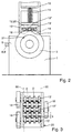
- a roller device 12 is provided to apply the load, which are a variety of stored in the body of the facility Rollers 13 has. These are referred to as roller shoes 20 designated device is parallel via a spring 14 switched damping he 15 in the load direction on the support member 16th the frame of the loading device 10 is supported.
- the support part 16 is opposite the frame in the direction of loading adjustable, but locked during measurements.
- the spring rate and damping the spring and damping device for the Roller shoe 20 essentially correspond to the spring rate and Damping the vehicle's wheel suspension.
- the roller shoe 20 is a low-friction bearing 17, in illustrated example of a roller or ball bearing, opposite the frame of the loading device 10 movable.
- Roller shoe 20 are five in the illustrated embodiment Rollers 13 mounted with their axes of rotation parallel to each other, where all axes of rotation lie in a common plane. Depending on the individual case a different number of roles can also be provided become.
- the common plane runs parallel to the balancing axis and perpendicular to the direction of loading.
- the roller shoe 20 is oriented that the roller axes run parallel to the balancing spindle axis.
- the roller shoe 20 is around the measuring direction axis pivotable, so that the roller axes in their plane also in Angle to the balancing spindle axis can be arranged.
- the inertial mass of the roller shoe 20 is essentially like that unsprung mass of the wheel unit 3 including unsprung attachments (Hub and brake, wheel carrier) chosen because of the conditions of the driving operation are optimally reproduced.
- the rollers 13 have sections of larger diameter and sections of smaller diameter (D, d) along their axis, which have approximately the same axial extent.
- D, d sections of smaller diameter
- rolls with only 4 or 3 sections of larger diameter are shown; however, more or fewer than 4 or 3 sections with a larger diameter can be provided.
- the tire width is indicated by dash-dotted lines and with the reference numbers 30.
- the arrangement of the rollers 13 in the roller shoe 20 is shown in FIG. 3 as a top view of the rollers 13.
- the sections of larger diameter D of a roller 13 are assigned sections of smaller diameter d of the adjacent roller 13, so that the center distance of two adjacent rollers is the same D / 2 + d / 2 + S may be, where S is the distance between the peripheral surfaces due to the non-contact arrangement of the adjacent rollers 13.
- At least one of the rollers 13 of the roller shoe 20 has a larger effective rotating mass, which in the case of only one roll with a larger rotating mass together with the Rotational mass of the remaining rollers on the tread radius reduced rotating mass of the vehicle wheel corresponds.
- three of the five rollers 13 have a larger one Turning mass on, each with a section at the end have greater moment of inertia 18. Overall corresponds the effective rotating mass of all roles involved in the reduced Rotational mass of the vehicle wheel.
- the two in the direction of the Tires outer rollers 13 ' have the section with larger diameter 18 on her with respect to the balancing machine inner ends, while the middle roller 13 '' this on the balancing machine has a technological end.
- the diameter of the sections 18 can be larger Mass moment of inertia should be chosen as large as possible.
- the sections 18 larger moments of inertia can also be axial be arranged offset to the largest possible diameter to enable.
- the wheel unit 3 is on the balancing spindle 2 of the balancing machine 1 clamped.
- the wheel unit 3 is brought to a speed by the motor 4 at which disturbing vibrations are noticeable (critical speed).
- This Speed is generally in the range of about 800 revolutions per minute, which is about a driving speed of 90 to Corresponds to 100 km / h. However, other speeds can also be used or speed ranges where critical Vibrations occur or are expected.
- the roller shoe 20 the loading device 10 is from the not shown Idle state in the pressure position shown in Figures 1 and 2 brought, the flattening of the tire by a predetermined vehicle load is determined.
- the vehicle loading can by changing the position of the support member 16 for the Spring 14 and the damping 15 are taken into account. It can however, it can also be provided that the load direction 10 even before or during the acceleration phase of the wheel unit 3 acts on the wheel unit 3.
- the rollers 13 of the roller shoe 20 now rotate together with their sections of greater moment of inertia 18 with one by the speed of the wheel unit 3 predetermined speed.
- the measurement of the vibrations of the Swinging bridges over the transducers 6, 6 'and their subsequent ones Evaluation using the rotor-synchronous reference signal of the angular position sensor 7 in the evaluation unit of the balancing machine 1 provides one for each level of the vehicle wheel Compensation mass according to size and angular position with which the vibrations be significantly reduced when driving.
- the Compensation masses are used, for example, as lead weights 31 attached to the rim flange of the vehicle wheel.
- contact pressure and the movements of the roller shoe can be specified programmatically so that the To reproduce conditions of a driving section of the vehicle.
Landscapes
- Physics & Mathematics (AREA)
- General Physics & Mathematics (AREA)
- Testing Of Balance (AREA)
Applications Claiming Priority (2)
| Application Number | Priority Date | Filing Date | Title |
|---|---|---|---|
| DE19909162 | 1999-03-03 | ||
| DE19909162A DE19909162A1 (de) | 1999-03-03 | 1999-03-03 | Verfahren zur Verringerung von durch eine Radeinheit eines Fahrzeuges hervorgerufenen Vibrationen und Einrichtung hierzu |
Publications (3)
| Publication Number | Publication Date |
|---|---|
| EP1033562A2 true EP1033562A2 (fr) | 2000-09-06 |
| EP1033562A3 EP1033562A3 (fr) | 2000-11-08 |
| EP1033562B1 EP1033562B1 (fr) | 2003-01-22 |
Family
ID=7899471
Family Applications (1)
| Application Number | Title | Priority Date | Filing Date |
|---|---|---|---|
| EP00104300A Expired - Lifetime EP1033562B1 (fr) | 1999-03-03 | 2000-03-02 | Procédé et dispositif de réduction des vibrations provoquées par une roue de véhicule |
Country Status (3)
| Country | Link |
|---|---|
| US (1) | US6360593B1 (fr) |
| EP (1) | EP1033562B1 (fr) |
| DE (2) | DE19909162A1 (fr) |
Cited By (4)
| Publication number | Priority date | Publication date | Assignee | Title |
|---|---|---|---|---|
| DE20116545U1 (de) | 2001-10-09 | 2002-01-17 | Dunlop GmbH, 63450 Hanau | Vorrichtung zur Messung der Eigenschaften von gummielastischen Reifen, insbesondere Kraftfahrzeugreifen |
| CN111238753A (zh) * | 2020-03-09 | 2020-06-05 | 北京航空航天大学 | 一种方便装卸的小振源大负载垂直振动实验台 |
| CN111968450A (zh) * | 2020-10-26 | 2020-11-20 | 成都运达科技股份有限公司 | 列车驾驶模拟器动感控制方法、装置、系统及存储介质 |
| CN113483670A (zh) * | 2021-08-27 | 2021-10-08 | 郑州华天机电装备有限公司 | 铁路车辆制动盘跳动自动测量机 |
Families Citing this family (17)
| Publication number | Priority date | Publication date | Assignee | Title |
|---|---|---|---|---|
| DE19962066B4 (de) * | 1999-12-22 | 2008-12-04 | Pwb-Ruhlatec Industrieprodukte Gmbh | Lenkwinkelsensoreinheit |
| US6578275B1 (en) * | 2001-08-17 | 2003-06-17 | Akron Special Machinery, Inc. | Loadwheel drive assembly and method |
| JP4177671B2 (ja) * | 2003-01-10 | 2008-11-05 | 住友ゴム工業株式会社 | タイヤ情報の提供方法及び提供装置 |
| US7270007B2 (en) * | 2005-06-03 | 2007-09-18 | Serrano Norman S | Apparatus and method for reducing vibration |
| ITMO20050226A1 (it) * | 2005-09-09 | 2007-03-10 | Sicam Srl | Macchina per l'equilibratura di ruote di veicoli |
| US7181971B1 (en) * | 2005-11-17 | 2007-02-27 | Autotech Innovations Llc | Automotive rattle detection system |
| ITMO20060267A1 (it) * | 2006-09-05 | 2008-03-06 | Sicam Srl | Macchina equilibratrice perfezionata per ruote di veicoli |
| DE102007025934B4 (de) * | 2007-06-04 | 2015-02-12 | Siemens Aktiengesellschaft | Werkzeugmaschine |
| JP5011361B2 (ja) * | 2009-09-25 | 2012-08-29 | 株式会社神戸製鋼所 | タイヤ試験機 |
| EP2587214B1 (fr) * | 2011-10-25 | 2013-12-11 | Snap-on Equipment Srl a unico socio | Détermination de non-uniformités de roues chargées par simulation de charge |
| US8793109B2 (en) * | 2011-10-25 | 2014-07-29 | Snap-On Equipment Srl A Unico Socio | Determination of non-uniformities of loaded wheels by load simulation |
| CN104422574B (zh) * | 2013-08-23 | 2017-09-01 | 超捷紧固系统(上海)股份有限公司 | 汽车动态载荷振动试验机 |
| KR101709330B1 (ko) * | 2015-04-07 | 2017-03-03 | 주식회사 다윈프릭션 | 항공기용 휠 브레이크 어셈블리의 토크 시험기 |
| CN107991231B (zh) * | 2017-11-14 | 2023-09-22 | 洛阳理工学院 | 一种用于摩擦磨损试验机的轴系压力加载系统 |
| CN107988888B (zh) * | 2017-12-22 | 2023-11-24 | 宜昌江峡船用机械有限责任公司 | 水泥路面破碎车影像辅助控制系统及减振装置 |
| CN112176836B (zh) * | 2020-10-03 | 2022-01-28 | 王玲 | 一种道路桥梁沥青路面裂缝检测装置 |
| KR102839869B1 (ko) * | 2022-08-02 | 2025-07-29 | (주)삼한엔지니어링 | 면접촉을 이용한 차량 쏠림 교정용 계측장치 |
Family Cites Families (19)
| Publication number | Priority date | Publication date | Assignee | Title |
|---|---|---|---|---|
| US2920481A (en) * | 1953-11-02 | 1960-01-12 | Us Rubber Co | Apparatus for determining the tendency of pneumatic tires to produce thump |
| US3412615A (en) * | 1965-09-30 | 1968-11-26 | Gen Motors Corp | Method of controlling vibrations of wheel and tire assemblies |
| US3575047A (en) | 1969-03-27 | 1971-04-13 | Hunter Eng Co | Radial tire force determining apparatus |
| US3589182A (en) * | 1969-06-25 | 1971-06-29 | Goodyear Tire & Rubber | Tire testing apparatus |
| US3862570A (en) * | 1973-01-26 | 1975-01-28 | Ongaro Dynamics | Tire symmetry measuring method and system |
| US4244416A (en) | 1976-07-28 | 1981-01-13 | Autodynamics, Inc. | Tire buffing machine system |
| DE3010315A1 (de) * | 1980-03-18 | 1981-09-24 | Carl Schenck Ag, 6100 Darmstadt | Maschine zur optimierung des laufverhaltens von reifen bzw. raedern |
| US4594878A (en) * | 1983-06-24 | 1986-06-17 | Nippo Sangyo Co. Ltd. | Dynamic friction coefficient measuring apparatus |
| US4655080A (en) | 1985-10-02 | 1987-04-07 | Theodore Ongaro | Dynamic tire balancing machine and method |
| NL8603022A (nl) | 1986-11-27 | 1988-06-16 | Hendrik Arie Boele | Correctie-inrichting voor voertuigwielen. |
| US5014551A (en) | 1989-09-22 | 1991-05-14 | Illinois Tool Works Inc. | Damped high speed tire testing machine |
| US5003819A (en) | 1990-01-02 | 1991-04-02 | Bridgestone/Firestone, Inc. | Suspension simulator |
| US5103595A (en) * | 1990-05-14 | 1992-04-14 | Fmc Corporation | Apparatus and method for reducing vibration characteristics in a wheel rim and tire assembly |
| DE4143543C2 (de) * | 1990-05-14 | 1998-03-26 | Fmc Corp | Verfahren zum Reduzieren von Betriebsvibrationscharakteristiken einer Anordnung aus Radfelge und Reifen |
| DE4220276A1 (de) * | 1991-07-10 | 1993-02-18 | Illinois Tool Works | Vorrichtung zur montage von halbfelgen in einer unwucht-pruefmaschine fuer reifen |
| DE4123681A1 (de) * | 1991-07-17 | 1993-01-21 | Aatec Assembling Automations T | Einrichtung zum ueberlastschutz und abbremsen eines durch einen motor angetriebenen maschinenteils |
| US5448910A (en) | 1994-03-07 | 1995-09-12 | Bridgestone/Firestone, Inc. | Portable tire uniformity test machine |
| EP0877920B1 (fr) | 1996-01-31 | 2008-01-09 | Hunter Engineering Company | Equilibreuse de roues a servomoteur |
| US5639962A (en) | 1996-03-06 | 1997-06-17 | The Goodyear Tire & Rubber Company | Enhanced tire uniformity machine data utilizing first and second derivative calculations |
-
1999
- 1999-03-03 DE DE19909162A patent/DE19909162A1/de not_active Withdrawn
-
2000
- 2000-03-01 US US09/516,398 patent/US6360593B1/en not_active Expired - Fee Related
- 2000-03-02 DE DE50001123T patent/DE50001123D1/de not_active Expired - Fee Related
- 2000-03-02 EP EP00104300A patent/EP1033562B1/fr not_active Expired - Lifetime
Cited By (5)
| Publication number | Priority date | Publication date | Assignee | Title |
|---|---|---|---|---|
| DE20116545U1 (de) | 2001-10-09 | 2002-01-17 | Dunlop GmbH, 63450 Hanau | Vorrichtung zur Messung der Eigenschaften von gummielastischen Reifen, insbesondere Kraftfahrzeugreifen |
| CN111238753A (zh) * | 2020-03-09 | 2020-06-05 | 北京航空航天大学 | 一种方便装卸的小振源大负载垂直振动实验台 |
| CN111968450A (zh) * | 2020-10-26 | 2020-11-20 | 成都运达科技股份有限公司 | 列车驾驶模拟器动感控制方法、装置、系统及存储介质 |
| CN113483670A (zh) * | 2021-08-27 | 2021-10-08 | 郑州华天机电装备有限公司 | 铁路车辆制动盘跳动自动测量机 |
| CN113483670B (zh) * | 2021-08-27 | 2023-10-31 | 郑州华天机电装备有限公司 | 铁路车辆制动盘跳动自动测量机 |
Also Published As
| Publication number | Publication date |
|---|---|
| EP1033562B1 (fr) | 2003-01-22 |
| DE50001123D1 (de) | 2003-02-27 |
| EP1033562A3 (fr) | 2000-11-08 |
| DE19909162A1 (de) | 2000-09-07 |
| US6360593B1 (en) | 2002-03-26 |
Similar Documents
| Publication | Publication Date | Title |
|---|---|---|
| EP1033562B1 (fr) | Procédé et dispositif de réduction des vibrations provoquées par une roue de véhicule | |
| DE19734904C2 (de) | Vorrichtung zur Messung der Gleichförmigkeit eines Fahrzeugreifens | |
| EP0232855B1 (fr) | Méthode et dispositif pour tester des roues de véhicule sur rails | |
| DE102012101613A1 (de) | Prüfstand für Kraftfahrzeuge | |
| DE3010315A1 (de) | Maschine zur optimierung des laufverhaltens von reifen bzw. raedern | |
| DE3614379C2 (fr) | ||
| DE69611344T2 (de) | Prüfvorrichtung für ein Rad mit Felge und Reifen mittels Führung des Rades über ein Hindernis | |
| DE69415494T2 (de) | Verfahren und vorrichtung für die verwendung von messmethoden zur bestimmung der rollreibung und des haftungsgrenzwertes | |
| DE2623281C3 (de) | Verfahren und Vorrichtung zur Verringerung von Reaktionskraftschwankungen längs des Umfangs eines unter Belastung gedrehten Luftreifens | |
| DE19704605C1 (de) | Vorrichtung zur Bestimmung und/oder zur Demonstration der auf die Profilelemente eines Fahrzeugrads wirkenden Kräfte | |
| EP1274977B1 (fr) | Dispositif pour la mesure de l'uniformite d'un pneu de vehicule automobile | |
| EP0730141B1 (fr) | Dispositif d'essai d'usure non-uniforme de la bande de roulement de pneumatiques de véhicule | |
| DE3913448A1 (de) | Testvorrichtung fuer fahrzeugreifen und antirutsch-einrichtungen | |
| DE2401279A1 (de) | Reifensymmetrie- messverfahren und -messeinrichtung | |
| DE2005105C3 (de) | Registriermeßvorrichtung zur Aufzeichnung der Exzentrizität von Rädern im belasteten Zustand | |
| DE69108437T2 (de) | An einer Felge montierter Reifen und Verfahren zur Unwuchtkorrektur. | |
| DE3714470A1 (de) | Verfahren und einrichtung zum ueberwachen von schwingungserregern in fahrwerkkomponenten bei kraftfahrzeugen waehrend des fahrbetriebs | |
| DE19704606C2 (de) | Vorrichtung zur Bestimmung und/oder Demonstration des Abrollverhaltens eines Fahrzeugreifens | |
| DE2701876A1 (de) | Vorrichtung zum auswuchten von rotoren, insbesondere fahrzeugraedern | |
| EP2189775B1 (fr) | Procédé et dispositif d'essai de l'équilibrage d'au moins une roue d'un véhicule automobile | |
| DE19719886A1 (de) | Verfahren zum Auswuchten von Rädern mit Luftreifen und Vorrichtung zum Durchführen des Verfahrens | |
| DE102022209270A1 (de) | Verfahren und Vorrichtung zur Materialtestung | |
| DE4312636C2 (de) | Fahrzeugprüfstand mit Wegstreckenmeßeinrichtung | |
| DE3905475C2 (de) | Verfahren zum Prüfen von Luftreifen | |
| DE3231852A1 (de) | Verfahren und vorrichtung zur qualitaetspruefung von reifen, insbesondere kraftfahrzeugreifen |
Legal Events
| Date | Code | Title | Description |
|---|---|---|---|
| PUAI | Public reference made under article 153(3) epc to a published international application that has entered the european phase |
Free format text: ORIGINAL CODE: 0009012 |
|
| AK | Designated contracting states |
Kind code of ref document: A2 Designated state(s): DE FR GB IT |
|
| AX | Request for extension of the european patent |
Free format text: AL;LT;LV;MK;RO;SI |
|
| PUAL | Search report despatched |
Free format text: ORIGINAL CODE: 0009013 |
|
| AK | Designated contracting states |
Kind code of ref document: A3 Designated state(s): AT BE CH CY DE DK ES FI FR GB GR IE IT LI LU MC NL PT SE |
|
| AX | Request for extension of the european patent |
Free format text: AL;LT;LV;MK;RO;SI |
|
| RIC1 | Information provided on ipc code assigned before grant |
Free format text: 7G 01M 17/02 A, 7G 01M 1/30 B |
|
| 17P | Request for examination filed |
Effective date: 20010317 |
|
| AKX | Designation fees paid |
Free format text: DE FR GB IT |
|
| 17Q | First examination report despatched |
Effective date: 20010823 |
|
| GRAG | Despatch of communication of intention to grant |
Free format text: ORIGINAL CODE: EPIDOS AGRA |
|
| GRAG | Despatch of communication of intention to grant |
Free format text: ORIGINAL CODE: EPIDOS AGRA |
|
| GRAH | Despatch of communication of intention to grant a patent |
Free format text: ORIGINAL CODE: EPIDOS IGRA |
|
| GRAH | Despatch of communication of intention to grant a patent |
Free format text: ORIGINAL CODE: EPIDOS IGRA |
|
| GRAA | (expected) grant |
Free format text: ORIGINAL CODE: 0009210 |
|
| AK | Designated contracting states |
Kind code of ref document: B1 Designated state(s): DE FR GB IT |
|
| REG | Reference to a national code |
Ref country code: GB Ref legal event code: FG4D Free format text: NOT ENGLISH |
|
| REF | Corresponds to: |
Ref document number: 50001123 Country of ref document: DE Date of ref document: 20030227 Kind code of ref document: P |
|
| GBT | Gb: translation of ep patent filed (gb section 77(6)(a)/1977) |
Effective date: 20030401 |
|
| ET | Fr: translation filed | ||
| PLBE | No opposition filed within time limit |
Free format text: ORIGINAL CODE: 0009261 |
|
| STAA | Information on the status of an ep patent application or granted ep patent |
Free format text: STATUS: NO OPPOSITION FILED WITHIN TIME LIMIT |
|
| 26N | No opposition filed |
Effective date: 20031023 |
|
| PGFP | Annual fee paid to national office [announced via postgrant information from national office to epo] |
Ref country code: GB Payment date: 20080228 Year of fee payment: 9 |
|
| PGFP | Annual fee paid to national office [announced via postgrant information from national office to epo] |
Ref country code: FR Payment date: 20080211 Year of fee payment: 9 |
|
| PGFP | Annual fee paid to national office [announced via postgrant information from national office to epo] |
Ref country code: DE Payment date: 20090527 Year of fee payment: 10 Ref country code: IT Payment date: 20090324 Year of fee payment: 10 |
|
| GBPC | Gb: european patent ceased through non-payment of renewal fee |
Effective date: 20090302 |
|
| REG | Reference to a national code |
Ref country code: FR Ref legal event code: ST Effective date: 20091130 |
|
| PG25 | Lapsed in a contracting state [announced via postgrant information from national office to epo] |
Ref country code: FR Free format text: LAPSE BECAUSE OF NON-PAYMENT OF DUE FEES Effective date: 20091123 Ref country code: GB Free format text: LAPSE BECAUSE OF NON-PAYMENT OF DUE FEES Effective date: 20090302 |
|
| PG25 | Lapsed in a contracting state [announced via postgrant information from national office to epo] |
Ref country code: DE Free format text: LAPSE BECAUSE OF NON-PAYMENT OF DUE FEES Effective date: 20101001 |
|
| PG25 | Lapsed in a contracting state [announced via postgrant information from national office to epo] |
Ref country code: IT Free format text: LAPSE BECAUSE OF NON-PAYMENT OF DUE FEES Effective date: 20100302 |