EP1033768A1 - Pile éléctrochimique enroulée à haute performance - Google Patents
Pile éléctrochimique enroulée à haute performance Download PDFInfo
- Publication number
- EP1033768A1 EP1033768A1 EP00300890A EP00300890A EP1033768A1 EP 1033768 A1 EP1033768 A1 EP 1033768A1 EP 00300890 A EP00300890 A EP 00300890A EP 00300890 A EP00300890 A EP 00300890A EP 1033768 A1 EP1033768 A1 EP 1033768A1
- Authority
- EP
- European Patent Office
- Prior art keywords
- electrode
- strip
- strips
- midportion
- assembly
- Prior art date
- Legal status (The legal status is an assumption and is not a legal conclusion. Google has not performed a legal analysis and makes no representation as to the accuracy of the status listed.)
- Granted
Links
Images




Classifications
-
- H—ELECTRICITY
- H01—ELECTRIC ELEMENTS
- H01G—CAPACITORS; CAPACITORS, RECTIFIERS, DETECTORS, SWITCHING DEVICES, LIGHT-SENSITIVE OR TEMPERATURE-SENSITIVE DEVICES OF THE ELECTROLYTIC TYPE
- H01G9/00—Electrolytic capacitors, rectifiers, detectors, switching devices, light-sensitive or temperature-sensitive devices; Processes of their manufacture
- H01G9/004—Details
- H01G9/04—Electrodes or formation of dielectric layers thereon
-
- H—ELECTRICITY
- H01—ELECTRIC ELEMENTS
- H01G—CAPACITORS; CAPACITORS, RECTIFIERS, DETECTORS, SWITCHING DEVICES, LIGHT-SENSITIVE OR TEMPERATURE-SENSITIVE DEVICES OF THE ELECTROLYTIC TYPE
- H01G9/00—Electrolytic capacitors, rectifiers, detectors, switching devices, light-sensitive or temperature-sensitive devices; Processes of their manufacture
-
- H—ELECTRICITY
- H01—ELECTRIC ELEMENTS
- H01M—PROCESSES OR MEANS, e.g. BATTERIES, FOR THE DIRECT CONVERSION OF CHEMICAL ENERGY INTO ELECTRICAL ENERGY
- H01M6/00—Primary cells; Manufacture thereof
- H01M6/04—Cells with aqueous electrolyte
- H01M6/06—Dry cells, i.e. cells wherein the electrolyte is rendered non-fluid
- H01M6/10—Dry cells, i.e. cells wherein the electrolyte is rendered non-fluid with wound or folded electrodes
-
- H—ELECTRICITY
- H01—ELECTRIC ELEMENTS
- H01M—PROCESSES OR MEANS, e.g. BATTERIES, FOR THE DIRECT CONVERSION OF CHEMICAL ENERGY INTO ELECTRICAL ENERGY
- H01M50/00—Constructional details or processes of manufacture of the non-active parts of electrochemical cells other than fuel cells, e.g. hybrid cells
- H01M50/10—Primary casings; Jackets or wrappings
- H01M50/102—Primary casings; Jackets or wrappings characterised by their shape or physical structure
- H01M50/103—Primary casings; Jackets or wrappings characterised by their shape or physical structure prismatic or rectangular
-
- Y—GENERAL TAGGING OF NEW TECHNOLOGICAL DEVELOPMENTS; GENERAL TAGGING OF CROSS-SECTIONAL TECHNOLOGIES SPANNING OVER SEVERAL SECTIONS OF THE IPC; TECHNICAL SUBJECTS COVERED BY FORMER USPC CROSS-REFERENCE ART COLLECTIONS [XRACs] AND DIGESTS
- Y02—TECHNOLOGIES OR APPLICATIONS FOR MITIGATION OR ADAPTATION AGAINST CLIMATE CHANGE
- Y02E—REDUCTION OF GREENHOUSE GAS [GHG] EMISSIONS, RELATED TO ENERGY GENERATION, TRANSMISSION OR DISTRIBUTION
- Y02E60/00—Enabling technologies; Technologies with a potential or indirect contribution to GHG emissions mitigation
- Y02E60/10—Energy storage using batteries
-
- Y—GENERAL TAGGING OF NEW TECHNOLOGICAL DEVELOPMENTS; GENERAL TAGGING OF CROSS-SECTIONAL TECHNOLOGIES SPANNING OVER SEVERAL SECTIONS OF THE IPC; TECHNICAL SUBJECTS COVERED BY FORMER USPC CROSS-REFERENCE ART COLLECTIONS [XRACs] AND DIGESTS
- Y02—TECHNOLOGIES OR APPLICATIONS FOR MITIGATION OR ADAPTATION AGAINST CLIMATE CHANGE
- Y02P—CLIMATE CHANGE MITIGATION TECHNOLOGIES IN THE PRODUCTION OR PROCESSING OF GOODS
- Y02P70/00—Climate change mitigation technologies in the production process for final industrial or consumer products
- Y02P70/50—Manufacturing or production processes characterised by the final manufactured product
-
- Y—GENERAL TAGGING OF NEW TECHNOLOGICAL DEVELOPMENTS; GENERAL TAGGING OF CROSS-SECTIONAL TECHNOLOGIES SPANNING OVER SEVERAL SECTIONS OF THE IPC; TECHNICAL SUBJECTS COVERED BY FORMER USPC CROSS-REFERENCE ART COLLECTIONS [XRACs] AND DIGESTS
- Y10—TECHNICAL SUBJECTS COVERED BY FORMER USPC
- Y10T—TECHNICAL SUBJECTS COVERED BY FORMER US CLASSIFICATION
- Y10T29/00—Metal working
- Y10T29/49—Method of mechanical manufacture
- Y10T29/49002—Electrical device making
- Y10T29/49108—Electric battery cell making
-
- Y—GENERAL TAGGING OF NEW TECHNOLOGICAL DEVELOPMENTS; GENERAL TAGGING OF CROSS-SECTIONAL TECHNOLOGIES SPANNING OVER SEVERAL SECTIONS OF THE IPC; TECHNICAL SUBJECTS COVERED BY FORMER USPC CROSS-REFERENCE ART COLLECTIONS [XRACs] AND DIGESTS
- Y10—TECHNICAL SUBJECTS COVERED BY FORMER USPC
- Y10T—TECHNICAL SUBJECTS COVERED BY FORMER US CLASSIFICATION
- Y10T29/00—Metal working
- Y10T29/49—Method of mechanical manufacture
- Y10T29/49002—Electrical device making
- Y10T29/49108—Electric battery cell making
- Y10T29/49112—Electric battery cell making including laminating of indefinite length material
Definitions
- the present invention generally relates to the art of electrochemical energy, and more particularly, to an electrode assembly, electrochemical cells in which the electrode assembly is used, and a method for making the electrode assembly.
- Batteries or electrochemical cells are typically volumetrically constrained systems that cannot exceed the available volume of the battery case.
- the size and resulting volume of the battery case are dictated by the space requirements available for the particular application.
- the components that make up a battery namely, the cathode electrode, the anode electrode, the separator, the current collectors, and the electrolyte all have to fit into the limited space defined by the battery case. Therefore, the arrangement of the components impacts on the amount of active electrode material that can be fit into the case and the ease of manufacturing the unit.
- Some typical electrode assemblies include the "Z" folded electrode assembly that is disclosed in U.S. Patent No. 3,663,721 to Blondel et al.
- the "Z" folded electrode a unitary and continuous lithium anode is folded back and forth in a zigzag fashion. The length of the individual folds determines the width of the electrode assembly.
- Individual cathode plates are positioned between pairs of the pleated anode electrode and electrically connected to one another.
- the design has some drawbacks, including the requirement that separate cathode plates be inserted between each pair of adjacent layers of anode electrode and the requirement that electrical connections be made between all of the inserted cathode plates. This arrangement increases the time and costs associated with manufacturing.
- Another typical electrode assembly configuration is the "jelly roll” design in which the anode electrode, the cathode electrode, and the separator are overlaid with respect to each other and coiled up.
- Such an electrode configuration is desirable because the continuous anode and cathode electrodes require a minimal number of mechanical connections to their respective terminal leads, and the jelly roll assembly is generally recognized as preferred for high discharge and current pulse applications.
- a cylindrically shaped electrode assembly is not desired because of other factors, such as the shape of the battery case.
- U.S. Patent No. 4,761,352 to Bakos et al. discloses yet another electrode assembly design comprising an accordion folded electrode assembly with unitary members for both the anode and cathode strips.
- the cathode strip is approximately half the length of the anode strip, and the anode strip is folded over the cathode strip to "sandwich" the cathode between two layers of the anode.
- the resulting form is then manually folded in an alternating series of "V" folds (best shown in Fig. 4 of the patent).
- that design provides some undesirable gaps which reduce the volumetric density of the electrochemically active materials. What is needed is an improved multi-layer, folded electrode assembly design for high energy devices that includes many of the desirable features of the jelly roll design, such as unitary anode and cathode electrodes.
- the present invention fills the above-described need by providing an electrochemical cell comprising an electrode assembly in which the electrodes are wound together in a bi-directional fashion, yielding a high energy density cell with low internal impedance.
- the anode and cathode electrodes are arranged in the cell in such a fashion that provides efficient utilization of the active components.
- the resultant wound assembly is configured such that it can be conveniently packaged in either a cylindrical or prismatic housing.
- the electrode assemblies are disposed such that either a single cathode is paired with two anodes or a single anode is paired with two cathodes prior to winding of the cell stack assembly.
- the cell stack assembly is formed by winding the electrodes starting at the centralmost portion of the assembly.
- the electrodes can be configured such that the two anodes (or two cathodes) are independent of each other or are electrically connected prior to winding. The resulting electrodes are then electrically connected to the battery housing.
- the electrodes are provided as two anode assemblies and one cathode assembly configured such that each anode is positioned on either side of the cathode assembly, and extending in opposing directions. At the centermost portion of the assembly there is an overlap of anodes. This assembly is then wound about the overlapping region in a bi-directional fashion. The resultant assembly produces a wound cell stack configuration with a uniform contact of anode and cathode, such that the cell is balanced electrochemically and provides for optimum volume utilization within the battery enclosure.
- Each anode has one or more tabs that can be welded to the case.
- two cathode assemblies can be paired with one anode assembly, with a resultant cathode tab welded to the case.
- the opposite electrode may contain one or more tabs which are then electrically connected to the battery feedthrough pin.
- An alternate embodiment of this invention provides for an anode electrode and a cathode electrode, wherein the electrodes are slotted. The electrodes are inserted, one into the other, essentially forming an "X.” Upon collapsing the electrodes, a variation of the above-described invention is obtained wherein the anode is approximately equally disposed about the cathode. This assembly is then wound from the center, resulting in a preferred cell stack assembly.
- This configuration provides for the additional advantage of having the anode registered to the cathode, and mitigates the need for aligning two distinct anodes to the cathode.
- the present invention is designed for high energy devices such as batteries and capacitors and is adaptable in a wide variety of electrode configurations and shapes for applications as capacitors and batteries, including aqueous and nonaqueous primary and secondary batteries.
- an electrode strip 10 is preferably a continuous structure comprising an active material combined with a current collector.
- the active material for a cathode electrode is preferably comprised of a metal, a metal oxide, a metal sulfide, a mixed metal oxide, a carbonaceous material, or the like and is combined with a current collector of a conductive material such as a conductive screen.
- the preferred active material is an alkali metal selected from Group 1A of the Periodic Table of Elements and contacted to a nickel current collector.
- An insulating separator material 13 prevents contact between adjoining layers of electrodes.
- the electrode strip 10 is a cathode electrode 14.
- the cathode electrode 14 has a set of cathode tabs 15 that are provided for making an electrical connection.
- Electrode strip 16 is part of anode electrode 18.
- Anode electrode 18 is also provided with a layer of separator material 13, and the electrode strip 16 has anode tabs 22 that provide for electrical connection.
- cathode electrode 14 and the two anode electrodes 18 are preferably elongate, flat, and rectangular.
- the anode electrodes 18 are disposed on opposite sides of the cathode and lined up such that they overlap across the midportion 19.
- the electrode strips 16 are approximately half the length of the electrode strip 10, and extend a short distance across the midportion 19 in order to overlap.
- two cathode electrode assemblies could be paired with one anode electrode.
- the electrode strips 10 and 16 are then folded about the overlapping region in bi-directional fashion to provide the electrode assembly 25, shown in Fig. 5.
- the term bi-directional refers to the fact that one side is folded downward and the opposite side is folded upward, in succession, to generate the electrode assembly 25 shown in Fig. 5.
- the electrode assembly 25 produces a wound cell stack configuration with uniform contact of anode and cathode such that the cell is balanced electrochemically and provides for optimum volume utilization within the battery enclose.
- the electrode assembly 25 provides several advantages, including producing a high energy density cell with low internal impedance.
- the anode and cathode electrodes 14, 18 are arranged in the cell in a way that provides efficient utilization of the active components.
- the resultant wound cell stack is configured such that it can be conveniently packaged in either a cylindrical or prismatic housing.
- the assembly 25 also provides a cell stack construction in which the anode and cathode are uniformly utilized during cell discharge.
- the assembly also provides for reduced internal cell resistance through the use of a dual anode (or dual cathode) configuration in combination with a single cathode (or anode).
- the assembly 25 provides for a cell that has a high current rate capability, which is advantageous for use in applications such as powering an implantable defibrillator.
- FIG. 6 An alternate embodiment of the present invention is shown in Fig. 6.
- a cathode electrode strip 50 has a slot 53 disposed in a midportion 56.
- An anode electrode strip 60 has a slot 63 disposed in a midportion 66.
- the strips 50 and 60 are inserted into each other to form a generally X-shaped member that is collapsible.
- a variation of the above-described invention is obtained wherein the anode is approximately equally disposed about the cathode.
- the strips 50, 60 are then folded in bi-directional fashion from the center to produce the electrode assembly 75, shown in Fig. 7.
- the alternate embodiment provides the additional advantage of having the anode registered to the cathode and mitigates the need for aligning two distinct anodes to the cathode.
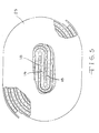
- the anode tabs 22 can be welded to the case 80 (negative). Alternately, two cathode assemblies can be paired with one anode assembly with the resultant cathode tabs (not shown) welded to the case 80 (positive). In both of the above configurations, the opposite electrode may contain one or more tabs (cathode tabs 15) that are electrically connected to the battery feedthrough pin 89.
Landscapes
- Engineering & Computer Science (AREA)
- Power Engineering (AREA)
- Microelectronics & Electronic Packaging (AREA)
- Manufacturing & Machinery (AREA)
- Chemical & Material Sciences (AREA)
- Chemical Kinetics & Catalysis (AREA)
- Electrochemistry (AREA)
- General Chemical & Material Sciences (AREA)
- Secondary Cells (AREA)
- Primary Cells (AREA)
- Battery Electrode And Active Subsutance (AREA)
- Connection Of Batteries Or Terminals (AREA)
Applications Claiming Priority (2)
| Application Number | Priority Date | Filing Date | Title |
|---|---|---|---|
| US26224599A | 1999-03-04 | 1999-03-04 | |
| US262245 | 1999-03-04 |
Publications (2)
| Publication Number | Publication Date |
|---|---|
| EP1033768A1 true EP1033768A1 (fr) | 2000-09-06 |
| EP1033768B1 EP1033768B1 (fr) | 2002-09-18 |
Family
ID=22996774
Family Applications (1)
| Application Number | Title | Priority Date | Filing Date |
|---|---|---|---|
| EP00300890A Expired - Lifetime EP1033768B1 (fr) | 1999-03-04 | 2000-02-04 | Pile éléctrochimique enroulée à haute performance |
Country Status (5)
| Country | Link |
|---|---|
| US (3) | US6383680B1 (fr) |
| EP (1) | EP1033768B1 (fr) |
| JP (1) | JP2000268844A (fr) |
| AT (1) | ATE224586T1 (fr) |
| DE (1) | DE60000460T2 (fr) |
Families Citing this family (19)
| Publication number | Priority date | Publication date | Assignee | Title |
|---|---|---|---|---|
| TW508861B (en) * | 2000-08-08 | 2002-11-01 | Matsushita Electric Industrial Co Ltd | Non-aqueous electrolyte secondary battery and positive electrode for the same |
| US7070881B2 (en) * | 2001-10-18 | 2006-07-04 | Quallion Llc | Electrical battery assembly and method of manufacture |
| US6805719B2 (en) * | 2002-04-15 | 2004-10-19 | Medtronic, Inc. | Balanced anode electrode |
| US7273674B1 (en) | 2003-02-27 | 2007-09-25 | Greatbatch Ltd. | Primary electrochemical cell having scalloped electrodes |
| US7108942B1 (en) * | 2003-03-27 | 2006-09-19 | Wilson Greatbatch Technologies, Inc. | Efficient electrode assembly design for cells with alkali metal anodes |
| EP1661195B1 (fr) * | 2003-08-18 | 2016-01-13 | PowerGenix Systems, Inc. | Procede de fabrication de piles nickel-zinc |
| KR100611940B1 (ko) * | 2003-11-21 | 2006-08-11 | 주식회사 엘지화학 | 안전성이 향상된 전기화학 전지 |
| US20060166088A1 (en) * | 2005-01-26 | 2006-07-27 | Hokanson Karl E | Electrode connector tabs |
| US8703330B2 (en) * | 2005-04-26 | 2014-04-22 | Powergenix Systems, Inc. | Nickel zinc battery design |
| US7875379B2 (en) * | 2005-07-08 | 2011-01-25 | Greatbatch Ltd. | Electrochemical cell having a pocket separator design |
| US7855009B2 (en) * | 2005-09-15 | 2010-12-21 | Greatbatch Ltd. | Sandwich cathode electrochemical cell with wound electrode assembly |
| JP4984553B2 (ja) * | 2006-01-30 | 2012-07-25 | ソニー株式会社 | 二次電池用負極及びそれを用いた二次電池 |
| KR100888284B1 (ko) | 2006-07-24 | 2009-03-10 | 주식회사 엘지화학 | 탭-리드 결합부의 전극간 저항차를 최소화한 전극조립체 및이를 포함하고 있는 전기화학 셀 |
| KR100848788B1 (ko) * | 2006-07-24 | 2008-07-30 | 주식회사 엘지화학 | 결합부에서 전극 탭들의 크기가 동일한 전극조립체 및 이를포함하고 있는 전기화학 셀 |
| US7718310B1 (en) | 2006-10-24 | 2010-05-18 | Greatbatch Ltd. | Electrochemical cell having a galaxy wind design |
| US20080289171A1 (en) * | 2007-05-22 | 2008-11-27 | Jason Cheng | Method for assembling a stacked plate electrochemical device |
| US20090068548A1 (en) * | 2007-09-06 | 2009-03-12 | Gillettte Company, The | Lithium Ion Prismatic Cells |
| EP2272124B1 (fr) * | 2008-04-02 | 2016-03-23 | PowerGenix Systems, Inc. | Cellule cylindrique au nickel-zinc ayant un boîtier négatif |
| US11670816B2 (en) | 2020-08-21 | 2023-06-06 | Greatbatch Ltd. | Glass-to-metal seal terminal pin for an electrochemical cell |
Citations (4)
| Publication number | Priority date | Publication date | Assignee | Title |
|---|---|---|---|---|
| EP0136886A2 (fr) * | 1983-09-30 | 1985-04-10 | Union Carbide Corporation | Assemblage d'électrodes |
| US4761352A (en) * | 1985-05-17 | 1988-08-02 | Eastman Kodak Company | Accordian folded electrode assembly |
| US5116698A (en) * | 1990-07-11 | 1992-05-26 | Eveready Battery Company, Inc. | Bifold separator |
| EP0512828A1 (fr) * | 1991-05-07 | 1992-11-11 | Wilson Greatbatch Ltd. | Pile électrochimique comportant une électrode ou serpentine à rendement amélioré |
Family Cites Families (21)
| Publication number | Priority date | Publication date | Assignee | Title |
|---|---|---|---|---|
| US317487A (en) | 1885-05-12 | Jules joas barrier | ||
| US1076485A (en) | 1913-10-21 | Alfred R Porter | Storage battery. | |
| US1088271A (en) | 1912-11-13 | 1914-02-24 | Treibacher Chemische Werke Gmbh | Lighter. |
| US1088272A (en) | 1913-10-18 | 1914-02-24 | Stone J & Co Ltd | Release mechanism for bulkhead-doors and the like. |
| US1269778A (en) | 1916-05-22 | 1918-06-18 | John P Mentzer | Storage battery. |
| GB1088272A (en) | 1963-04-04 | 1967-10-25 | Burndept Ltd | Electric cells |
| GB1088271A (en) | 1963-04-04 | 1967-10-25 | Burndept Ltd | Electric cells |
| US4064725A (en) | 1976-10-18 | 1977-12-27 | The Gates Rubber Company | Apparatus for making spirally wound electrochemical cells |
| US4099401A (en) | 1977-06-27 | 1978-07-11 | The Gates Rubber Company | Method of producing spirally wound electrochemical cells |
| US4158300A (en) | 1977-12-16 | 1979-06-19 | The Gates Rubber Company | Apparatus for producing a spirally wound electrochemical cell |
| US4212179A (en) | 1978-10-12 | 1980-07-15 | The Gates Rubber Company | Driven mandrel and method |
| US4637966A (en) | 1983-10-21 | 1987-01-20 | Gates Energy Products, Inc. | Sealed lead-acid cell |
| US4802275A (en) | 1987-03-12 | 1989-02-07 | Saft, S.A. | Method of manufacturing an electrochemical cell having an alkaline electrolyte and spiral-wound electrodes |
| DE3902648A1 (de) | 1989-01-30 | 1990-08-09 | Varta Batterie | Galvanisches element |
| US5045086A (en) | 1989-06-14 | 1991-09-03 | Bolder Battery, Inc. | Method for manufacture of electrochemical cell |
| US5091273A (en) | 1990-06-11 | 1992-02-25 | Optima Batteries, Inc. | Method of applying a tail wrap to a wound electrochemical cell and cell produced by the method |
| EP0556326A4 (en) | 1990-11-09 | 1995-03-29 | Weiler Eng Inc | Method and apparatus for winding a core for an electrochemical cell and processing thereof |
| US5370711A (en) | 1993-07-21 | 1994-12-06 | Ev Energy Systems, Inc. | Method for making an electrical energy storage device |
| KR100189808B1 (ko) * | 1996-06-10 | 1999-06-01 | 손욱 | 권취 극판군 |
| JPH10125348A (ja) * | 1996-10-21 | 1998-05-15 | Japan Storage Battery Co Ltd | 電 池 |
| FR2761200B1 (fr) | 1997-03-24 | 1999-04-16 | Alsthom Cge Alcatel | Generateur electrochimique a bobineau spirale |
-
2000
- 2000-02-04 DE DE60000460T patent/DE60000460T2/de not_active Expired - Lifetime
- 2000-02-04 EP EP00300890A patent/EP1033768B1/fr not_active Expired - Lifetime
- 2000-02-04 AT AT00300890T patent/ATE224586T1/de not_active IP Right Cessation
- 2000-03-06 JP JP2000059934A patent/JP2000268844A/ja active Pending
-
2001
- 2001-10-11 US US09/975,268 patent/US6383680B1/en not_active Expired - Lifetime
- 2001-10-11 US US09/975,349 patent/US6423442B1/en not_active Expired - Lifetime
- 2001-10-11 US US09/974,950 patent/US6425928B2/en not_active Expired - Lifetime
Patent Citations (4)
| Publication number | Priority date | Publication date | Assignee | Title |
|---|---|---|---|---|
| EP0136886A2 (fr) * | 1983-09-30 | 1985-04-10 | Union Carbide Corporation | Assemblage d'électrodes |
| US4761352A (en) * | 1985-05-17 | 1988-08-02 | Eastman Kodak Company | Accordian folded electrode assembly |
| US5116698A (en) * | 1990-07-11 | 1992-05-26 | Eveready Battery Company, Inc. | Bifold separator |
| EP0512828A1 (fr) * | 1991-05-07 | 1992-11-11 | Wilson Greatbatch Ltd. | Pile électrochimique comportant une électrode ou serpentine à rendement amélioré |
Also Published As
| Publication number | Publication date |
|---|---|
| DE60000460D1 (de) | 2002-10-24 |
| ATE224586T1 (de) | 2002-10-15 |
| EP1033768B1 (fr) | 2002-09-18 |
| JP2000268844A (ja) | 2000-09-29 |
| DE60000460T2 (de) | 2003-06-05 |
| US20020022175A1 (en) | 2002-02-21 |
| US20020018928A1 (en) | 2002-02-14 |
| US6423442B1 (en) | 2002-07-23 |
| US6425928B2 (en) | 2002-07-30 |
| US20020022174A1 (en) | 2002-02-21 |
| US6383680B1 (en) | 2002-05-07 |
Similar Documents
| Publication | Publication Date | Title |
|---|---|---|
| EP1033768B1 (fr) | Pile éléctrochimique enroulée à haute performance | |
| US6037077A (en) | Electrode assembly for high energy devices | |
| EP0512828B1 (fr) | Pile électrochimique comportant une électrode ou serpentine à rendement amélioré | |
| US6893772B2 (en) | Current collector for lithium electrode | |
| US6420066B1 (en) | Variable density cathode assembly which facilitates winding | |
| US5525441A (en) | Folded electrode configuration for galvanic cells | |
| EP0555422B1 (fr) | Accumulateur d'energie ameliore | |
| US5667909A (en) | Electrodes configured for high energy density galvanic cells | |
| US6461759B1 (en) | Cathode assembly with bare current collector regions to facilitate winding | |
| JP5014982B2 (ja) | 低インピーダンス積層電池装置とその製造方法 | |
| KR100624953B1 (ko) | 리튬 이차 전지 | |
| JP3531552B2 (ja) | 積層型電池・キャパシタ用電極構造体 | |
| US7035078B1 (en) | Folded plate electrode assemblies for battery cathodes | |
| US7592097B2 (en) | Electrochemical cell designs with anode plates and connections which facilitate heat dissipation | |
| US6045943A (en) | Electrode assembly for high energy density batteries | |
| JPH10241725A (ja) | アルカリ二次電池 | |
| JPH09320636A (ja) | 非水電解液二次電池 | |
| KR20000076959A (ko) | 사각형 배터리 | |
| JPH04167375A (ja) | 角型リチウム二次電池 | |
| JPH0822816A (ja) | 角形密閉電池 | |
| KR100514215B1 (ko) | 다열 접착을 이용한 적층형 리튬이차전지의 제조방법 | |
| JP2986512B2 (ja) | 角形電池 | |
| JP2003109656A (ja) | 蓄電池 | |
| JP2000268806A (ja) | 電池用端子 | |
| JPH04298973A (ja) | 角型リチウム二次電池 |
Legal Events
| Date | Code | Title | Description |
|---|---|---|---|
| PUAI | Public reference made under article 153(3) epc to a published international application that has entered the european phase |
Free format text: ORIGINAL CODE: 0009012 |
|
| AK | Designated contracting states |
Kind code of ref document: A1 Designated state(s): AT BE CH CY DE DK ES FI FR GB GR IE IT LI LU MC NL PT SE |
|
| AX | Request for extension of the european patent |
Free format text: AL;LT;LV;MK;RO;SI |
|
| 17P | Request for examination filed |
Effective date: 20010213 |
|
| 17Q | First examination report despatched |
Effective date: 20010322 |
|
| AKX | Designation fees paid |
Free format text: AT BE CH CY DE DK ES FI FR GB GR IE IT LI LU MC NL PT SE |
|
| GRAG | Despatch of communication of intention to grant |
Free format text: ORIGINAL CODE: EPIDOS AGRA |
|
| GRAG | Despatch of communication of intention to grant |
Free format text: ORIGINAL CODE: EPIDOS AGRA |
|
| GRAG | Despatch of communication of intention to grant |
Free format text: ORIGINAL CODE: EPIDOS AGRA |
|
| GRAH | Despatch of communication of intention to grant a patent |
Free format text: ORIGINAL CODE: EPIDOS IGRA |
|
| GRAH | Despatch of communication of intention to grant a patent |
Free format text: ORIGINAL CODE: EPIDOS IGRA |
|
| GRAA | (expected) grant |
Free format text: ORIGINAL CODE: 0009210 |
|
| AK | Designated contracting states |
Kind code of ref document: B1 Designated state(s): AT BE CH CY DE DK ES FI FR GB GR IE IT LI LU MC NL PT SE |
|
| PG25 | Lapsed in a contracting state [announced via postgrant information from national office to epo] |
Ref country code: GR Free format text: LAPSE BECAUSE OF FAILURE TO SUBMIT A TRANSLATION OF THE DESCRIPTION OR TO PAY THE FEE WITHIN THE PRESCRIBED TIME-LIMIT Effective date: 20020918 Ref country code: AT Free format text: LAPSE BECAUSE OF FAILURE TO SUBMIT A TRANSLATION OF THE DESCRIPTION OR TO PAY THE FEE WITHIN THE PRESCRIBED TIME-LIMIT Effective date: 20020918 Ref country code: FI Free format text: LAPSE BECAUSE OF FAILURE TO SUBMIT A TRANSLATION OF THE DESCRIPTION OR TO PAY THE FEE WITHIN THE PRESCRIBED TIME-LIMIT Effective date: 20020918 Ref country code: BE Free format text: LAPSE BECAUSE OF FAILURE TO SUBMIT A TRANSLATION OF THE DESCRIPTION OR TO PAY THE FEE WITHIN THE PRESCRIBED TIME-LIMIT Effective date: 20020918 |
|
| REF | Corresponds to: |
Ref document number: 224586 Country of ref document: AT Date of ref document: 20021015 Kind code of ref document: T |
|
| REG | Reference to a national code |
Ref country code: GB Ref legal event code: FG4D |
|
| REG | Reference to a national code |
Ref country code: CH Ref legal event code: EP |
|
| REF | Corresponds to: |
Ref document number: 60000460 Country of ref document: DE Date of ref document: 20021024 |
|
| PG25 | Lapsed in a contracting state [announced via postgrant information from national office to epo] |
Ref country code: DK Free format text: LAPSE BECAUSE OF FAILURE TO SUBMIT A TRANSLATION OF THE DESCRIPTION OR TO PAY THE FEE WITHIN THE PRESCRIBED TIME-LIMIT Effective date: 20021218 |
|
| PG25 | Lapsed in a contracting state [announced via postgrant information from national office to epo] |
Ref country code: PT Free format text: LAPSE BECAUSE OF FAILURE TO SUBMIT A TRANSLATION OF THE DESCRIPTION OR TO PAY THE FEE WITHIN THE PRESCRIBED TIME-LIMIT Effective date: 20021219 |
|
| REG | Reference to a national code |
Ref country code: CH Ref legal event code: NV Representative=s name: ISLER & PEDRAZZINI AG |
|
| PG25 | Lapsed in a contracting state [announced via postgrant information from national office to epo] |
Ref country code: CY Free format text: LAPSE BECAUSE OF FAILURE TO SUBMIT A TRANSLATION OF THE DESCRIPTION OR TO PAY THE FEE WITHIN THE PRESCRIBED TIME-LIMIT Effective date: 20030204 Ref country code: IE Free format text: LAPSE BECAUSE OF NON-PAYMENT OF DUE FEES Effective date: 20030204 Ref country code: LU Free format text: LAPSE BECAUSE OF NON-PAYMENT OF DUE FEES Effective date: 20030204 |
|
| PG25 | Lapsed in a contracting state [announced via postgrant information from national office to epo] |
Ref country code: MC Free format text: LAPSE BECAUSE OF NON-PAYMENT OF DUE FEES Effective date: 20030228 |
|
| ET | Fr: translation filed | ||
| PG25 | Lapsed in a contracting state [announced via postgrant information from national office to epo] |
Ref country code: ES Free format text: LAPSE BECAUSE OF FAILURE TO SUBMIT A TRANSLATION OF THE DESCRIPTION OR TO PAY THE FEE WITHIN THE PRESCRIBED TIME-LIMIT Effective date: 20030328 |
|
| PLBE | No opposition filed within time limit |
Free format text: ORIGINAL CODE: 0009261 |
|
| STAA | Information on the status of an ep patent application or granted ep patent |
Free format text: STATUS: NO OPPOSITION FILED WITHIN TIME LIMIT |
|
| 26N | No opposition filed |
Effective date: 20030619 |
|
| REG | Reference to a national code |
Ref country code: IE Ref legal event code: MM4A |
|
| PGFP | Annual fee paid to national office [announced via postgrant information from national office to epo] |
Ref country code: NL Payment date: 20050214 Year of fee payment: 6 |
|
| PGFP | Annual fee paid to national office [announced via postgrant information from national office to epo] |
Ref country code: CH Payment date: 20050218 Year of fee payment: 6 |
|
| PG25 | Lapsed in a contracting state [announced via postgrant information from national office to epo] |
Ref country code: LI Free format text: LAPSE BECAUSE OF NON-PAYMENT OF DUE FEES Effective date: 20060228 Ref country code: CH Free format text: LAPSE BECAUSE OF NON-PAYMENT OF DUE FEES Effective date: 20060228 |
|
| PGFP | Annual fee paid to national office [announced via postgrant information from national office to epo] |
Ref country code: IT Payment date: 20060228 Year of fee payment: 7 |
|
| PG25 | Lapsed in a contracting state [announced via postgrant information from national office to epo] |
Ref country code: NL Free format text: LAPSE BECAUSE OF NON-PAYMENT OF DUE FEES Effective date: 20060901 |
|
| REG | Reference to a national code |
Ref country code: CH Ref legal event code: PL |
|
| NLV4 | Nl: lapsed or anulled due to non-payment of the annual fee |
Effective date: 20060901 |
|
| PG25 | Lapsed in a contracting state [announced via postgrant information from national office to epo] |
Ref country code: SE Free format text: LAPSE BECAUSE OF NON-PAYMENT OF DUE FEES Effective date: 20070205 |
|
| EUG | Se: european patent has lapsed | ||
| GBPC | Gb: european patent ceased through non-payment of renewal fee |
Effective date: 20070204 |
|
| PGFP | Annual fee paid to national office [announced via postgrant information from national office to epo] |
Ref country code: SE Payment date: 20060227 Year of fee payment: 7 |
|
| PG25 | Lapsed in a contracting state [announced via postgrant information from national office to epo] |
Ref country code: GB Free format text: LAPSE BECAUSE OF NON-PAYMENT OF DUE FEES Effective date: 20070204 |
|
| PGFP | Annual fee paid to national office [announced via postgrant information from national office to epo] |
Ref country code: GB Payment date: 20060223 Year of fee payment: 7 |
|
| PG25 | Lapsed in a contracting state [announced via postgrant information from national office to epo] |
Ref country code: IT Free format text: LAPSE BECAUSE OF NON-PAYMENT OF DUE FEES Effective date: 20070204 |
|
| REG | Reference to a national code |
Ref country code: FR Ref legal event code: PLFP Year of fee payment: 16 |
|
| REG | Reference to a national code |
Ref country code: FR Ref legal event code: PLFP Year of fee payment: 17 |
|
| REG | Reference to a national code |
Ref country code: FR Ref legal event code: PLFP Year of fee payment: 18 |
|
| REG | Reference to a national code |
Ref country code: FR Ref legal event code: PLFP Year of fee payment: 19 |
|
| PGFP | Annual fee paid to national office [announced via postgrant information from national office to epo] |
Ref country code: DE Payment date: 20190122 Year of fee payment: 20 Ref country code: FR Payment date: 20190111 Year of fee payment: 20 |
|
| REG | Reference to a national code |
Ref country code: DE Ref legal event code: R071 Ref document number: 60000460 Country of ref document: DE |