EP1034092B2 - Systeme electrique pour vehicule - Google Patents
Systeme electrique pour vehicule Download PDFInfo
- Publication number
- EP1034092B2 EP1034092B2 EP98962266A EP98962266A EP1034092B2 EP 1034092 B2 EP1034092 B2 EP 1034092B2 EP 98962266 A EP98962266 A EP 98962266A EP 98962266 A EP98962266 A EP 98962266A EP 1034092 B2 EP1034092 B2 EP 1034092B2
- Authority
- EP
- European Patent Office
- Prior art keywords
- onboard electrical
- electrical subsystem
- generator
- starter
- subsystem
- Prior art date
- Legal status (The legal status is an assumption and is not a legal conclusion. Google has not performed a legal analysis and makes no representation as to the accuracy of the status listed.)
- Expired - Lifetime
Links
Images
Classifications
-
- H—ELECTRICITY
- H02—GENERATION; CONVERSION OR DISTRIBUTION OF ELECTRIC POWER
- H02J—ELECTRIC POWER NETWORKS; CIRCUIT ARRANGEMENTS OR SYSTEMS FOR SUPPLYING OR DISTRIBUTING ELECTRIC POWER; SYSTEMS FOR STORING ELECTRIC ENERGY
- H02J1/00—Circuit arrangements for DC mains or DC distribution networks
- H02J1/08—Three-wire DC power distribution systems; Systems having more than three wires
-
- B—PERFORMING OPERATIONS; TRANSPORTING
- B60—VEHICLES IN GENERAL
- B60R—VEHICLES, VEHICLE FITTINGS, OR VEHICLE PARTS, NOT OTHERWISE PROVIDED FOR
- B60R16/00—Electric or fluid circuits specially adapted for vehicles and not otherwise provided for; Arrangement of elements of electric or fluid circuits specially adapted for vehicles and not otherwise provided for
- B60R16/02—Electric or fluid circuits specially adapted for vehicles and not otherwise provided for; Arrangement of elements of electric or fluid circuits specially adapted for vehicles and not otherwise provided for electric constitutive elements
- B60R16/03—Electric or fluid circuits specially adapted for vehicles and not otherwise provided for; Arrangement of elements of electric or fluid circuits specially adapted for vehicles and not otherwise provided for electric constitutive elements for supply of electrical power to vehicle subsystems or for
-
- H—ELECTRICITY
- H02—GENERATION; CONVERSION OR DISTRIBUTION OF ELECTRIC POWER
- H02J—ELECTRIC POWER NETWORKS; CIRCUIT ARRANGEMENTS OR SYSTEMS FOR SUPPLYING OR DISTRIBUTING ELECTRIC POWER; SYSTEMS FOR STORING ELECTRIC ENERGY
- H02J1/00—Circuit arrangements for DC mains or DC distribution networks
- H02J1/08—Three-wire DC power distribution systems; Systems having more than three wires
- H02J1/082—DC supplies with two or more different DC voltage levels
-
- H—ELECTRICITY
- H02—GENERATION; CONVERSION OR DISTRIBUTION OF ELECTRIC POWER
- H02J—ELECTRIC POWER NETWORKS; CIRCUIT ARRANGEMENTS OR SYSTEMS FOR SUPPLYING OR DISTRIBUTING ELECTRIC POWER; SYSTEMS FOR STORING ELECTRIC ENERGY
- H02J2105/00—Networks for supplying or distributing electric power characterised by their spatial reach or by the load
- H02J2105/30—Networks for supplying or distributing electric power characterised by their spatial reach or by the load the load networks being external to vehicles, i.e. exchanging power with vehicles
- H02J2105/33—Networks for supplying or distributing electric power characterised by their spatial reach or by the load the load networks being external to vehicles, i.e. exchanging power with vehicles exchanging power with road vehicles
Definitions
- the invention relates to a vehicle electrical system for a motor vehicle according to claim 1.
- vehicle electrical systems are used in particular for connecting consumers to on-board energy storage, in particular a battery, and on-board power generator, in particular a starter generator coupled to the motor vehicle internal combustion engine; If high-current consumers are also connected to the vehicle electrical system, it is expedient for loss minimization to supply a second voltage, which is higher than a first battery-side voltage, to supply them.
- a vehicle electrical system which receives its power from a starter / generator, which is connected via pulse inverters and a 300 volt DC link and a bidirectional converter with a 24 volt ring network and a 24 volt battery, with other consumers higher voltage than 24 volts and a socket with 220 volt 50 Hz voltage from the Bornetzsystem be supplied.
- WO 97/08456 discloses a starter / generator for an internal combustion engine for a motor vehicle, comprising an inverter for generating the voltages required by the electric machine.
- the inverter is connected to a vehicle electrical system at a low voltage level (12 V) and converts this low voltage to a higher intermediate circuit level and vice versa.
- low voltage loads are connected and at the higher voltage level the starter / generator and other higher voltage loads are connected.
- a second vehicle electrical system voltage is to be made available with the least possible outlay in terms of hardware and software.
- the solution to this problem is achieved according to the invention by a built-up according to claim 1 electrical system; advantageous embodiments of the invention are the subject of the dependent claims.
- the electrical system according to the invention makes it possible to charge with the help of the switching or connecting device with only one boost converter on the one hand a starting capacitor for the starter-generator with a correspondingly high voltage or the second board power supply from the battery and on the other hand in the generator mode of Starter generator using the inverter associated with the starter-generator to supply the second on-board power supply by appropriate control of the inverter with a voltage that is increased relative to the battery voltage and compared to the voltage of the starter-generator is reduced.
- the starting capacitor is then used as a DC link capacitor in the generator mode.
- the electrical switching or connecting device consists in circuitry particularly low expenditure of a first connection from the first on-board power supply to the third on-board power supply with blocking in the opposite direction, further from a second connection from the first on-board power supply to the second on-board power supply with blocking in the opposite direction and switching only when powering the second on-board power supply from the first on-board power supply and from a third connection from the third on-board power supply to the second on-board power supply with switching only when feeding the second on-board power supply from the third on-board power supply provided;
- for blocking in the opposite direction diodes and for switching on or switching off the individual switchable connections depending on a Tyristor or transistor, in particular IGBT provided.
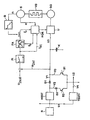
- the electrical system shown in the figure can basically be divided into a first onboard power supply U1 with a voltage level of e.g. 12 volts corresponding to the voltage of the battery B, into a second on-board power supply U2 for supplying high current consumers with a voltage level of e.g. 180 volts, into a third on-board power supply U3 with a voltage level of e.g.
- a control part is used for energy-optimal operation of the intended as a starter generator SG asynchronous machine, preferably with squirrel cage.
- an electrical switching or connecting device V1-V3 with a first connection V1 from the first on-board power supply U1 to the third on-board power supply U3 with blocking in the opposite direction and with a second connection V2 from the first on-board power supply U1 to the second on-board power supply U2 with switching on only when feeding the second on-board power supply unit U2 from the first on-board power supply unit U1 and with a third connection V3 from the third power supply unit
- the second on-board power supply unit U2 can be connected to the second vehicle electrical system voltage of, for example, by closing the switch S2 in the connection V2 by means of the step-up converter HSST. 180 volts brought and be supplied with energy from the battery B.
- the diode D1 remains in the locked state, since the starting capacitor K is usually at a relative to the voltage level of the second board power supply U2 increased voltage level.
- the internal combustion engine VB can be raised to a speed of approximately 400-700 rpm with the aid of the asynchronous motor of the starter generator SG; in the case of an electronic valve control, the valves are suitably fully opened during startup and thus provided without compression.
- the internal combustion engine VB can be ignited in normal valve position and the starter generator SG can be switched off on the drive side.
- the energy pre-stored in the starting capacitor K is insufficient, in the event that the voltage level of the third on-board power supply U3 is smaller than the voltage level of the second on-board power supply U2, additional energy from the battery B via the boost converter HSST and the connection V1 for the supplied via the inverter U starter generator SG are related.
- the starter generator SG can go into the generator mode.
- the voltage level of the third on-board power supply unit U3 as intermediate circuit voltage via the converter U and the starting capacitor K expediently used as intermediate circuit capacitor is reduced to the voltage level of the second onboard power supply unit U2, e.g. to 180 volts, regulated.
- the switch S2 is opened and thus the connection V2 is interrupted and the switch S1 is closed and thus the connection V3 is established by the on-board power supply unit U3 for the on-board power supply unit U2; the boost converter HSST is expediently put out of operation.
- the starter generator SG now operates in generator mode and supplies the regulated power supply U2 and the high-current consumers connected thereto via the regulated intermediate circuit voltage of the onboard power supply U3.
- a buck converter TSST DC-DC converter
- the electrical losses in both the inverter U and provided for the starter-generator SG asynchronous machine advantageously characterized low held that in a field-oriented control FOR the internal moment M i1 of the induction machine of the starter generator SG on the principle of loss-optimal control or regulation of the rotor flux by appropriate adaptation of the magnetizing current i ' u as a function of a corresponding to the respective required drive torque determined active current i sq is set.
- the field-oriented control of the asynchronous machine is based on the mathematical description of the dynamic machine behavior with room pointer sizes.
- Field orientation means that one connects the freely selectable reference axis of this mathematical machine model with respect to their angular position with the Rotorflußraum adapter, the Statorflußraum adapter or the Lucasspaltflußraum adapter.
- the mathematically simplest machine structure and thus also the simplest structure of a control result when the rotor flow space vector is selected as the orientation variable.
- the structure of the machine then resembles in the specification of the stator current space hand of a separately excited compensated DC machine.
- the field-oriented control of the asynchronous machine is achieved by predetermining the components of the stator current indicator of the machine, shown in the field-oriented coordinate system, as controlled variables. By means of a simple decoupling, the magnitude of the flux space vector and the internal torque are independently controllable.
- the intermediate circuit voltage according to the voltage level of the second board power supply U2 on the one hand and the desired value u 2 is to this intermediate circuit voltage is expected, and in a PI-formers of corresponding active current i sq defined.
- the corresponding magnetizing current i ⁇ ' is determined in accordance with the aforementioned formulas according to the principle of loss-optimal field-oriented regulation f S in a frequency adapter FA and via the field-oriented regulation FOR of the converter U or the asynchronous machine the starter-generator SG driven.
- the magnetizing current i ⁇ ' is additionally advantageously set as a function of a limiter B, such that the magnetizing current can be limited at a higher rotational speed, in particular to prevent thermal overload or in the sense of a field weakening operation.
Landscapes
- Engineering & Computer Science (AREA)
- Power Engineering (AREA)
- Control Of Eletrric Generators (AREA)
Claims (9)
- Réseau de bord pour un véhicule automobile, comprenant- une première partie de réseau de bord (U1) pouvant être alimentée en particulier par une batterie (B) d'un véhicule automobile, destinée à alimenter des consommateurs à une première basse tension,- une deuxième partie de réseau de bord (U2) destinée à alimenter des consommateurs à une deuxième tension plus élevée et- une troisième partie de réseau de bord (U3) prévue pour le fonctionnement en démarreur, ou pour le fonctionnement en génératrice d'un démarreur-génératrice (SG) pouvant être accouplé à un moteur à combustion interne (VB), cette troisième partie ayant une troisième tension pour le fonctionnement en démarreur, et- un dispositif de commutation ou de liaison (V1-V3) comprenant- une première liaison (V1) entre la première partie de réseau de bord (U1) et la troisième partie de réseau de bord (U3) qui comprend un dispositif de blocage en sens inverse (D1) par l'intermédiaire duquel la première partie de réseau de bord (U1) peut être reliée pour l'alimentation, par l'intermédiaire d'un élévateur de tension (HSST), à la troisième partie de réseau de bord (U3) dans le fonctionnement en démarreur du démarreur-génératrice (SG) ;- une deuxième liaison (V2) entre la première partie de réseau de bord (U1) et la deuxième partie de réseau de bord (U2) qui comprend un dispositif d'établissement de circuit (S2) seulement lorsque la deuxième partie de réseau de bord (U2) est alimentée à partir de la première partie de réseau de bord (U1), dispositif d'établissement par l'intermédiaire duquel la première partie de réseau de bord (U1) peut être reliée pour l'alimentation avec la deuxième partie de réseau de bord par l'intermédiaire d'un élévateur de tension (HSST) ;- caractérisé en ce qu'il comprend également- une troisième liaison (V3) entre la troisième partie de réseau de bord (U3) et la deuxième partie de réseau de bord (U3) qui comprend un dispositif d'établissement de circuit (S1) seulement lorsque la deuxième partie de réseau de bord (U2) est alimentée à partir de la troisième partie de réseau de bord (U3) en fonctionnement en génératrice, dispositif d'établissement par l'intermédiaire duquel la troisième partie de réseau de bord (U3) peut être reliée pour l'alimentation à la deuxième partie de réseau de bord (U2) dans le fonctionnement en génératrice du démarreur-génératrice (SG).
- Réseau de bord selon la revendication 1, comprenant- une alimentation du démarreur-génératrice (SG) dans la première partie de réseau de bord (U1) par l'intermédiaire de la deuxième partie de réseau de bord (U2) dans le fonctionnement en génératrice.
- Réseau de bord selon la revendication 2, comprenant- une quatrième liaison (V4) reliant la deuxième partie de réseau de bord (U2) à la première partie de réseau de bord (U1) par l'intermédiaire d'un abaisseur de tension (TSST).
- Réseau de bord selon une des revendications précédentes 1-3, comprenant- un redresseur (U) associé au démarreur-génératrice (SG) en tant que partie de la troisième partie de réseau de bord (U3).
- Réseau de bord selon une des revendications précédentes 1-4, comprenant- un condensateur de démarrage (K) associé au démarreur-génératrice (SG) en tant que partie de la troisième partie de réseau de bord (U3).
- Réseau de bord selon une des revendications précédentes 4 ou 5, comprenant- une utilisation du condensateur de démarrage (K) également en tant que condensateur de circuit intermédiaire du redresseur (U) dans le fonctionnement en génératrice du démarreur-génératrice (SG).
- Réseau de bord selon au moins l'une des revendications précédentes, comprenant- une machine asynchrone réglée de façon orientée sur le flux dans le rotor en qualité de démarreur-génératrice (SG).
- Réseau de bord selon la revendication précédente, comprenant- une régulation du couple intérieur :

de la machine asynchrone en application du principe de l'adaptation optimale sous le rapport des pertes du courant de magnétisation (i'µ ) en fonction d'une valeur de consigne de courant actif (iw) obtenue en fonction du couple d'entraînement demandé à chaque fois, ainsi que de la fréquence du stator (fs). - Réseau de bord selon au moins une des revendications précédentes 7 ou 8, comprenant :- un limiteur destiné à la limitation du courant de magnétisation (i'µ ) en fonction de la vitesse de rotation (n) de la machine asynchrone.
Applications Claiming Priority (3)
| Application Number | Priority Date | Filing Date | Title |
|---|---|---|---|
| DE1997152661 DE19752661C2 (de) | 1997-11-27 | 1997-11-27 | Bordnetz für ein Kraftfahrzeug |
| DE19752661 | 1997-11-27 | ||
| PCT/DE1998/003354 WO1999028157A1 (fr) | 1997-11-27 | 1998-11-16 | Systeme electrique pour vehicule |
Publications (3)
| Publication Number | Publication Date |
|---|---|
| EP1034092A1 EP1034092A1 (fr) | 2000-09-13 |
| EP1034092B1 EP1034092B1 (fr) | 2004-08-18 |
| EP1034092B2 true EP1034092B2 (fr) | 2007-12-12 |
Family
ID=7850021
Family Applications (1)
| Application Number | Title | Priority Date | Filing Date |
|---|---|---|---|
| EP98962266A Expired - Lifetime EP1034092B2 (fr) | 1997-11-27 | 1998-11-16 | Systeme electrique pour vehicule |
Country Status (4)
| Country | Link |
|---|---|
| US (1) | US6320274B1 (fr) |
| EP (1) | EP1034092B2 (fr) |
| DE (2) | DE19752661C2 (fr) |
| WO (1) | WO1999028157A1 (fr) |
Families Citing this family (23)
| Publication number | Priority date | Publication date | Assignee | Title |
|---|---|---|---|---|
| DE19953373B4 (de) * | 1999-11-06 | 2004-07-15 | Audi Ag | Vorrichtung zur Spannungsversorgung in einem Kraftfahrzeug |
| DE19958098C2 (de) * | 1999-12-02 | 2003-04-10 | Trw Automotive Electron & Comp | Stromversorgung für Fahrzeuge |
| US6629044B1 (en) * | 2000-03-17 | 2003-09-30 | General Electric Company | Electrical distribution analysis method and apparatus |
| DE10027182C1 (de) | 2000-05-31 | 2001-10-31 | Siemens Ag | Vorrichtung zur Energieversorgung eines Zündmittels eines Insassenrückhaltemittels |
| JP2002036980A (ja) * | 2000-07-21 | 2002-02-06 | Toshiba Corp | 自動車用モータ駆動方法及びそのシステム |
| EP1186463A1 (fr) * | 2000-08-28 | 2002-03-13 | Siemens Aktiengesellschaft | Méthode pour actionner l'entraínement d'une machine à combustion interne et d'une machine électrique |
| EP1245452A1 (fr) | 2001-03-30 | 2002-10-02 | Siemens Aktiengesellschaft | Réseau de bord de véhicule, particulièrement pour un poids lourd |
| US20030197991A1 (en) * | 2002-04-08 | 2003-10-23 | Visteon Global Technologies, Inc. | System for providing power to an electrical system in a vehicle |
| EP1363379A3 (fr) * | 2002-05-13 | 2004-01-02 | Luxon Energy Devices Corporation | Module de puissance pour générer des impulsions à des niveaux différents |
| EP1424494A1 (fr) * | 2002-11-27 | 2004-06-02 | Continental ISAD Electronic Systems GmbH & Co. oHG | Dispositif de propulsion hybride et méthode pour l'application commune d'un couple de propulsion |
| US8131878B2 (en) * | 2004-11-11 | 2012-03-06 | International Business Machines Corporation | Selective disruption of data transmission to sub-networks within a processing unit network |
| FR2878088B1 (fr) * | 2004-11-18 | 2007-03-30 | Renault Sas | Systeme d'alimentation en energie electrique multi-tension pour reseau de bord d'un vehicule automobile |
| DE102004062939B4 (de) * | 2004-12-28 | 2019-02-21 | Volkswagen Ag | Verfahren und Vorrichtung zum optimierten Starten eines Verbrennungsmotors |
| DE102005015658A1 (de) | 2005-04-06 | 2007-01-11 | Bayerische Motoren Werke Ag | Schalteinrichtung zur Verknüpfung verschiedener elektrischer Spannungsebenen in einem Kraftfahrzeug |
| US20080288132A1 (en) | 2007-05-16 | 2008-11-20 | General Electric Company | Method of operating vehicle and associated system |
| US7889524B2 (en) | 2007-10-19 | 2011-02-15 | Illinois Institute Of Technology | Integrated bi-directional converter for plug-in hybrid electric vehicles |
| WO2009062227A1 (fr) * | 2007-11-14 | 2009-05-22 | Renergyx Pty Limited | Système de fourniture et de distribution d'énergie électrique |
| FR2945996B1 (fr) | 2009-05-29 | 2012-10-12 | Peugeot Citroen Automobiles Sa | Systeme d'alimentation electrique d'un vehicule a moteur thermique muni d'un dispositif d'arret et de redemarrage automatique |
| JP5297953B2 (ja) * | 2009-09-08 | 2013-09-25 | トヨタ自動車株式会社 | 電動車両の電動機駆動システム |
| DE102010047017A1 (de) * | 2010-09-30 | 2012-04-05 | Voith Patent Gmbh | Verfahren zur Ansteuerung einer umrichtergespeisten Asynchronmaschine |
| DE102013009801A1 (de) * | 2013-06-12 | 2014-12-18 | Audi Ag | Kraftfahrzeug mit zwei Bordnetzen mit unterschiedlichen Bordnetzspannungen |
| US10479218B2 (en) | 2017-02-14 | 2019-11-19 | Toyota Motor Engineering & Manufacturing North America, Inc. | Electric vehicle power system with shared converter |
| JP6989539B2 (ja) * | 2019-01-21 | 2022-01-05 | 本田技研工業株式会社 | 車両 |
Citations (2)
| Publication number | Priority date | Publication date | Assignee | Title |
|---|---|---|---|---|
| DE3812577A1 (de) † | 1988-04-15 | 1989-10-26 | Bosch Gmbh Robert | Bordnetz fuer ein kraftfahrzeug |
| WO1997008456A1 (fr) † | 1995-08-31 | 1997-03-06 | Isad Electronic Systems Gmbh & Co. Kg | Demarreur/generateur pour moteur a combustion interne, notamment d'automobile |
Family Cites Families (8)
| Publication number | Priority date | Publication date | Assignee | Title |
|---|---|---|---|---|
| US4672294A (en) * | 1986-01-24 | 1987-06-09 | Peter Norton | Dual battery system with improved overvoltage protection |
| US4723079A (en) * | 1986-03-27 | 1988-02-02 | Peter Norton | Vehicle power supply with regulated voltage and adjustable voltage outputs |
| US5175439A (en) * | 1987-12-21 | 1992-12-29 | Robert Bosch Gmbh | Power supply circuit for motor vehicles |
| DE3743317A1 (de) * | 1987-12-21 | 1989-06-29 | Bosch Gmbh Robert | Fahrzeugbordnetzsystem |
| DE3743316A1 (de) * | 1987-12-21 | 1989-06-29 | Bosch Gmbh Robert | Fahrzeugbordnetzsystem |
| JP3039119B2 (ja) | 1992-03-31 | 2000-05-08 | 日産自動車株式会社 | 車両用電源装置 |
| JP3516361B2 (ja) * | 1995-01-17 | 2004-04-05 | 富士重工業株式会社 | 車両用電源装置 |
| DE19646043A1 (de) * | 1996-11-08 | 1998-05-14 | Bosch Gmbh Robert | Vorrichtung zur Spannungsversorgung |
-
1997
- 1997-11-27 DE DE1997152661 patent/DE19752661C2/de not_active Revoked
-
1998
- 1998-11-16 DE DE59811843T patent/DE59811843D1/de not_active Expired - Lifetime
- 1998-11-16 WO PCT/DE1998/003354 patent/WO1999028157A1/fr not_active Ceased
- 1998-11-16 EP EP98962266A patent/EP1034092B2/fr not_active Expired - Lifetime
-
2000
- 2000-05-30 US US09/580,550 patent/US6320274B1/en not_active Expired - Fee Related
Patent Citations (2)
| Publication number | Priority date | Publication date | Assignee | Title |
|---|---|---|---|---|
| DE3812577A1 (de) † | 1988-04-15 | 1989-10-26 | Bosch Gmbh Robert | Bordnetz fuer ein kraftfahrzeug |
| WO1997008456A1 (fr) † | 1995-08-31 | 1997-03-06 | Isad Electronic Systems Gmbh & Co. Kg | Demarreur/generateur pour moteur a combustion interne, notamment d'automobile |
Also Published As
| Publication number | Publication date |
|---|---|
| DE59811843D1 (de) | 2004-09-23 |
| WO1999028157A1 (fr) | 1999-06-10 |
| US6320274B1 (en) | 2001-11-20 |
| DE19752661C2 (de) | 2001-09-13 |
| EP1034092A1 (fr) | 2000-09-13 |
| EP1034092B1 (fr) | 2004-08-18 |
| DE19752661A1 (de) | 1999-06-10 |
Similar Documents
| Publication | Publication Date | Title |
|---|---|---|
| EP1034092B2 (fr) | Systeme electrique pour vehicule | |
| DE60319570T2 (de) | Hybridkraftfahrzeug mit steuerungsvorrichtung zum laden der batterie | |
| DE60119419T2 (de) | Gerät für die Steuerung eines permanenten Magnetmotors, entweder als Anlasser oder als Generator in einem Kraftfahrzeug | |
| EP2541755B1 (fr) | Dispositif d'entraînement pour un véhicule | |
| DE102010001250B4 (de) | Elektrisches Bordnetz sowie Verfahren zum Betreiben eines elektrischen Bordnetzes | |
| DE102004057693B4 (de) | Vorrichtung zur schnellen Entladung eines Kondensators | |
| DE10231379B3 (de) | Antriebssystem für ein Kraftfahrzeug mit einem Verbrennungsmotor und einer elektrischen Maschine | |
| EP2365919A1 (fr) | Agencement de propulsion pour véhicule à propulsion électrique | |
| EP0929927B1 (fr) | Procede pour reguler un generateur | |
| DE102010034441B4 (de) | Energieversorgungssystem für ein Motorfahrzeug | |
| EP2707245B1 (fr) | Dispositif électronique de puissance et procédé de commande pour un moteur électrique et des accumulateurs d'énergie électriques | |
| DE102010017417A1 (de) | Elektrisches Versorgungs- und Startsystem für ein Kraftfahrzeug und Verfahren zum Betrieb des elektrischen Versorgungs- und Startsystems | |
| WO2004006422A1 (fr) | Reseau de bord de vehicule automobile | |
| DE19838296A1 (de) | Elektrisches Spannungsversorgungssystem | |
| DE10256704B3 (de) | Schaltungs für ein KFZ-Bordnetz und zugehöriges Betriebsverfahren | |
| EP1410482B1 (fr) | Dispositif d'entrainement pour un vehicule automobile | |
| EP1313628B1 (fr) | Procede permettant de faire fonctionner un mecanisme d'entrainement avec un moteur a combustion interne et une machine electrique | |
| EP2157313A2 (fr) | Dispositif et procédé destinés au soutien d'un démarreur dans un véhicule automobile | |
| DE102010025266A1 (de) | Transportfahrzeug mit einer Mehrzahl elektrischer Maschinen | |
| DE102013206296A1 (de) | Verfahren zum Betreiben einer Energieversorgungseinheit für ein Kraftfahrzeugbordnetz | |
| DE102004040228B4 (de) | Fahrzeug mit Elektroantrieb | |
| EP1507679A1 (fr) | Systeme d'entrainement pour vehicule comprenant un moteur a combustion interne et un moteur electrique | |
| EP1360411B1 (fr) | Ensemble circuit pour un generateur, notamment pour un generateur-demarreur integre | |
| EP1110799B2 (fr) | Ensemble d'entraînement | |
| DE102011086734B4 (de) | Verfahren zum Betreiben einer Energieversorgungseinheit für ein Bordnetz eines Kraftfahrzeugs |
Legal Events
| Date | Code | Title | Description |
|---|---|---|---|
| PUAI | Public reference made under article 153(3) epc to a published international application that has entered the european phase |
Free format text: ORIGINAL CODE: 0009012 |
|
| 17P | Request for examination filed |
Effective date: 20000417 |
|
| AK | Designated contracting states |
Kind code of ref document: A1 Designated state(s): DE FR GB IT |
|
| 17Q | First examination report despatched |
Effective date: 20030919 |
|
| GRAP | Despatch of communication of intention to grant a patent |
Free format text: ORIGINAL CODE: EPIDOSNIGR1 |
|
| GRAA | (expected) grant |
Free format text: ORIGINAL CODE: 0009210 |
|
| GRAS | Grant fee paid |
Free format text: ORIGINAL CODE: EPIDOSNIGR3 |
|
| AK | Designated contracting states |
Kind code of ref document: B1 Designated state(s): DE FR GB IT |
|
| REG | Reference to a national code |
Ref country code: GB Ref legal event code: FG4D Free format text: NOT ENGLISH |
|
| GBT | Gb: translation of ep patent filed (gb section 77(6)(a)/1977) |
Effective date: 20040818 |
|
| REF | Corresponds to: |
Ref document number: 59811843 Country of ref document: DE Date of ref document: 20040923 Kind code of ref document: P |
|
| PLAQ | Examination of admissibility of opposition: information related to despatch of communication + time limit deleted |
Free format text: ORIGINAL CODE: EPIDOSDOPE2 |
|
| PLBQ | Unpublished change to opponent data |
Free format text: ORIGINAL CODE: EPIDOS OPPO |
|
| PLBI | Opposition filed |
Free format text: ORIGINAL CODE: 0009260 |
|
| ET | Fr: translation filed | ||
| PLAX | Notice of opposition and request to file observation + time limit sent |
Free format text: ORIGINAL CODE: EPIDOSNOBS2 |
|
| 26 | Opposition filed |
Opponent name: CONTI TEMIC MICROELECTRONIC GMBH Effective date: 20050510 |
|
| PLAF | Information modified related to communication of a notice of opposition and request to file observations + time limit |
Free format text: ORIGINAL CODE: EPIDOSCOBS2 |
|
| PLBB | Reply of patent proprietor to notice(s) of opposition received |
Free format text: ORIGINAL CODE: EPIDOSNOBS3 |
|
| PUAH | Patent maintained in amended form |
Free format text: ORIGINAL CODE: 0009272 |
|
| STAA | Information on the status of an ep patent application or granted ep patent |
Free format text: STATUS: PATENT MAINTAINED AS AMENDED |
|
| 27A | Patent maintained in amended form |
Effective date: 20071212 |
|
| AK | Designated contracting states |
Kind code of ref document: B2 Designated state(s): DE FR GB IT |
|
| RAP2 | Party data changed (patent owner data changed or rights of a patent transferred) |
Owner name: SIEMENS VDO AUTOMOTIVE AG |
|
| GBTA | Gb: translation of amended ep patent filed (gb section 77(6)(b)/1977) | ||
| REG | Reference to a national code |
Ref country code: GB Ref legal event code: 732E |
|
| REG | Reference to a national code |
Ref country code: FR Ref legal event code: TP |
|
| ET3 | Fr: translation filed ** decision concerning opposition | ||
| PGFP | Annual fee paid to national office [announced via postgrant information from national office to epo] |
Ref country code: IT Payment date: 20081122 Year of fee payment: 11 |
|
| PGFP | Annual fee paid to national office [announced via postgrant information from national office to epo] |
Ref country code: FR Payment date: 20081113 Year of fee payment: 11 |
|
| PGFP | Annual fee paid to national office [announced via postgrant information from national office to epo] |
Ref country code: GB Payment date: 20081117 Year of fee payment: 11 |
|
| GBPC | Gb: european patent ceased through non-payment of renewal fee |
Effective date: 20091116 |
|
| REG | Reference to a national code |
Ref country code: FR Ref legal event code: ST Effective date: 20100730 |
|
| PG25 | Lapsed in a contracting state [announced via postgrant information from national office to epo] |
Ref country code: FR Free format text: LAPSE BECAUSE OF NON-PAYMENT OF DUE FEES Effective date: 20091130 |
|
| PG25 | Lapsed in a contracting state [announced via postgrant information from national office to epo] |
Ref country code: GB Free format text: LAPSE BECAUSE OF NON-PAYMENT OF DUE FEES Effective date: 20091116 |
|
| PG25 | Lapsed in a contracting state [announced via postgrant information from national office to epo] |
Ref country code: IT Free format text: LAPSE BECAUSE OF NON-PAYMENT OF DUE FEES Effective date: 20091116 |
|
| PGFP | Annual fee paid to national office [announced via postgrant information from national office to epo] |
Ref country code: DE Payment date: 20121130 Year of fee payment: 15 |
|
| REG | Reference to a national code |
Ref country code: DE Ref legal event code: R119 Ref document number: 59811843 Country of ref document: DE Effective date: 20140603 |
|
| PG25 | Lapsed in a contracting state [announced via postgrant information from national office to epo] |
Ref country code: DE Free format text: LAPSE BECAUSE OF NON-PAYMENT OF DUE FEES Effective date: 20140603 |