EP1034449B1 - Regulation de temperature pour methode d'observation au microscope - Google Patents
Regulation de temperature pour methode d'observation au microscope Download PDFInfo
- Publication number
- EP1034449B1 EP1034449B1 EP97950897A EP97950897A EP1034449B1 EP 1034449 B1 EP1034449 B1 EP 1034449B1 EP 97950897 A EP97950897 A EP 97950897A EP 97950897 A EP97950897 A EP 97950897A EP 1034449 B1 EP1034449 B1 EP 1034449B1
- Authority
- EP
- European Patent Office
- Prior art keywords
- sample
- temperature
- housing
- flow
- internal
- Prior art date
- Legal status (The legal status is an assumption and is not a legal conclusion. Google has not performed a legal analysis and makes no representation as to the accuracy of the status listed.)
- Expired - Lifetime
Links
- 238000000386 microscopy Methods 0.000 title claims abstract description 10
- 239000000463 material Substances 0.000 claims description 14
- 238000001816 cooling Methods 0.000 claims description 12
- 238000005057 refrigeration Methods 0.000 claims description 12
- 239000011810 insulating material Substances 0.000 claims description 7
- 239000004800 polyvinyl chloride Substances 0.000 claims description 5
- 229910052782 aluminium Inorganic materials 0.000 claims description 4
- XAGFODPZIPBFFR-UHFFFAOYSA-N aluminium Chemical compound [Al] XAGFODPZIPBFFR-UHFFFAOYSA-N 0.000 claims description 4
- 239000004020 conductor Substances 0.000 claims description 3
- 239000007799 cork Substances 0.000 claims description 3
- 238000010438 heat treatment Methods 0.000 claims description 3
- 239000002245 particle Substances 0.000 claims description 3
- 229920000915 polyvinyl chloride Polymers 0.000 claims description 3
- 229910001369 Brass Inorganic materials 0.000 claims description 2
- OKTJSMMVPCPJKN-UHFFFAOYSA-N Carbon Chemical compound [C] OKTJSMMVPCPJKN-UHFFFAOYSA-N 0.000 claims description 2
- 229910000975 Carbon steel Inorganic materials 0.000 claims description 2
- 239000010951 brass Substances 0.000 claims description 2
- 239000010962 carbon steel Substances 0.000 claims description 2
- PCHJSUWPFVWCPO-UHFFFAOYSA-N gold Chemical compound [Au] PCHJSUWPFVWCPO-UHFFFAOYSA-N 0.000 claims description 2
- 239000010931 gold Substances 0.000 claims description 2
- 229910052737 gold Inorganic materials 0.000 claims description 2
- 229910002804 graphite Inorganic materials 0.000 claims description 2
- 239000010439 graphite Substances 0.000 claims description 2
- 229920002635 polyurethane Polymers 0.000 claims description 2
- 239000004814 polyurethane Substances 0.000 claims description 2
- 238000012544 monitoring process Methods 0.000 claims 2
- 208000035484 Cellulite Diseases 0.000 claims 1
- 206010049752 Peau d'orange Diseases 0.000 claims 1
- 230000036232 cellulite Effects 0.000 claims 1
- 230000000284 resting effect Effects 0.000 claims 1
- 238000012546 transfer Methods 0.000 abstract description 2
- 239000000758 substrate Substances 0.000 abstract 1
- 239000012530 fluid Substances 0.000 description 23
- 230000001276 controlling effect Effects 0.000 description 14
- 239000007789 gas Substances 0.000 description 12
- IJGRMHOSHXDMSA-UHFFFAOYSA-N Atomic nitrogen Chemical compound N#N IJGRMHOSHXDMSA-UHFFFAOYSA-N 0.000 description 11
- 229910052757 nitrogen Inorganic materials 0.000 description 5
- RYGMFSIKBFXOCR-UHFFFAOYSA-N Copper Chemical compound [Cu] RYGMFSIKBFXOCR-UHFFFAOYSA-N 0.000 description 3
- 229910052802 copper Inorganic materials 0.000 description 3
- 239000010949 copper Substances 0.000 description 3
- 239000007788 liquid Substances 0.000 description 3
- 238000010276 construction Methods 0.000 description 2
- 229910052751 metal Inorganic materials 0.000 description 2
- 239000002184 metal Substances 0.000 description 2
- 229920002160 Celluloid Polymers 0.000 description 1
- 239000004743 Polypropylene Substances 0.000 description 1
- 238000004630 atomic force microscopy Methods 0.000 description 1
- 238000009835 boiling Methods 0.000 description 1
- 230000006835 compression Effects 0.000 description 1
- 238000007906 compression Methods 0.000 description 1
- 230000000694 effects Effects 0.000 description 1
- 229920001971 elastomer Polymers 0.000 description 1
- 238000005516 engineering process Methods 0.000 description 1
- 238000002474 experimental method Methods 0.000 description 1
- 238000005259 measurement Methods 0.000 description 1
- 238000000034 method Methods 0.000 description 1
- 238000000399 optical microscopy Methods 0.000 description 1
- 239000004033 plastic Substances 0.000 description 1
- 229920003023 plastic Polymers 0.000 description 1
- 239000004417 polycarbonate Substances 0.000 description 1
- 229920000515 polycarbonate Polymers 0.000 description 1
- 229920000642 polymer Polymers 0.000 description 1
- -1 polypropylene Polymers 0.000 description 1
- 229920001155 polypropylene Polymers 0.000 description 1
- 230000001681 protective effect Effects 0.000 description 1
- 230000001105 regulatory effect Effects 0.000 description 1
- 238000006467 substitution reaction Methods 0.000 description 1
- 238000012360 testing method Methods 0.000 description 1
Images



Classifications
-
- G—PHYSICS
- G01—MEASURING; TESTING
- G01Q—SCANNING-PROBE TECHNIQUES OR APPARATUS; APPLICATIONS OF SCANNING-PROBE TECHNIQUES, e.g. SCANNING PROBE MICROSCOPY [SPM]
- G01Q30/00—Auxiliary means serving to assist or improve the scanning probe techniques or apparatus, e.g. display or data processing devices
- G01Q30/08—Means for establishing or regulating a desired environmental condition within a sample chamber
- G01Q30/10—Thermal environment
-
- G—PHYSICS
- G02—OPTICS
- G02B—OPTICAL ELEMENTS, SYSTEMS OR APPARATUS
- G02B21/00—Microscopes
- G02B21/24—Base structure
- G02B21/28—Base structure with cooling device
-
- G—PHYSICS
- G02—OPTICS
- G02B—OPTICAL ELEMENTS, SYSTEMS OR APPARATUS
- G02B21/00—Microscopes
- G02B21/24—Base structure
- G02B21/30—Base structure with heating device
-
- G—PHYSICS
- G05—CONTROLLING; REGULATING
- G05D—SYSTEMS FOR CONTROLLING OR REGULATING NON-ELECTRIC VARIABLES
- G05D23/00—Control of temperature
- G05D23/19—Control of temperature characterised by the use of electric means
- G05D23/1919—Control of temperature characterised by the use of electric means characterised by the type of controller
-
- G—PHYSICS
- G05—CONTROLLING; REGULATING
- G05D—SYSTEMS FOR CONTROLLING OR REGULATING NON-ELECTRIC VARIABLES
- G05D23/00—Control of temperature
- G05D23/19—Control of temperature characterised by the use of electric means
- G05D23/20—Control of temperature characterised by the use of electric means with sensing elements having variation of electric or magnetic properties with change of temperature
- G05D23/22—Control of temperature characterised by the use of electric means with sensing elements having variation of electric or magnetic properties with change of temperature the sensing element being a thermocouple
Definitions
- This invention relates to temperature control for microscopy.
- the present invention is directed to an apparatus and a method whereby such materials may be observed at different temperatures using microscopy, such as atomic force microscopy (afm), as well as light microscopy.
- microscopy such as atomic force microscopy (afm)
- afm atomic force microscopy
- Fig. 1 illustrates one possible embodiment of the temperature control apparatus of the invention.
- Fig. 2 illustrates a side view of a housing of a temperature control apparatus of the invention.
- Fig. 3 illustrates a top view of the housing illustrated in Fig. 2.
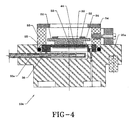
- Fig. 4 illustrates a preferred embodiment of a housing for temperature control of a sample.
- Fig. 5 illustrates a top view of a sample holder of the housing of Fig. 4.
- an illustrated variable temperature control device 10 of the invention includes a sample holding portion 12, temperature control center 14, and fluid source 16.
- sample holding portion 12 comprises an exterior housing 20 made of a highly heat insulating material and construction having a heat conductivity of 0.00001 to 0.25, preferably 0.02 to 0.15 W/m-K (watt per meter Kelvin), and an interior housing 22 made of a low heat insulating material having a heat conductivity of 20 to 2000, preferably 50 to 400 W/m-K, and sample holder 24.
- Examples of highly heat insulating materials used to make exterior housing 20 are polyvinyl chloride (PVC), celluloid, particle board, cork, and foamed polyurethane.
- Examples of low heat insulating material used to make the interior housing 22 are aluminum, copper, carbon steel, pyrolytic graphite, gold and brass.
- a highly heat insulating material is used to make outer housing 20 to help prevent heat transfer to or from external housing 20 to the surroundings, which saves energy and helps maintain a constant temperature within external housing 20 with little or no fluctuation.
- the low heat insulating material i.e. highly heat conductive material used to make internal housing 22 aids in quickly drawing heat from or transferring heat to the sample so that a substantially constant sample temperature can be quickly achieved and maintained using the temperature control devices associated with temperature control center 14.
- external housing 20 may enhance the insulating effect of the material used to make the housing. For example, if a material having a heat conductivity outside the range described above is used, and the material is used to make a double walled exterior housing, the effective insulating properties of the exterior housing may be in the range described, even though the material used has properties outside the range.
- the temperature at which a sample is maintained during microscopy may also have some bearing on the materials chosen for fabricating the temperature control device of the invention. For example, if samples are maintained at 200° C, PVC may soften and break down, and coated cork or particle board may be preferred for making exterior housing 20. Other material substitutions will be apparent to those skilled in the art.
- temperature control is achieved using counter balancing temperature raising and lowering devices.
- fluid 16a such as nitrogen (N 2 ) gas
- cooling means 26a can conveniently be a liquefied or solidified gas, such as N 2 , CO 2 , He, or Ar.
- N 2 nitrogen
- Cooling means 26a can conveniently be a liquefied or solidified gas, such as N 2 , CO 2 , He, or Ar.
- mechanical refrigeration can be used for cooling means 26a, especially if only mild cooling is needed.
- heaters 30,34,36 may be employed to raise the temperature of temperature controlling fluid 16a.
- Flow buffer 48 provides a reservoir for compression and expansion of the gas to help smooth out the gas flow since solenoid valve 50 operates only to turn on and turn off the flow of the gas.
- a pressure of 5 to 30 psi (pounds per square inch) corresponding to 34,5 to 207 kPa for the temperature controlling gas in the system is desirable, and pressures in the lower end of the range are preferred.
- the controlled flow of fluid then passes through refrigerator means 26. If cooling is desired, the gas flows through cooling means 26a and exits refrigeration means 26 through tubing 28a.
- heater 34 may be placed adjacent tubing 28a downstream of refrigeration means 26, and optional thermocouple 32b may be placed in tubing 28a in the proximity of heater 34.
- thermocouples may be provided, for example thermocouple 32a in exterior housing 20, in the path of temperature controlling fluid 16a as desired.
- the temperature of the fluid 16a can be controlled somewhat by the choice of cooling means 26a and by the amount of time fluid 16a spends in cooling means 26a, such time being dependant on the flow rate of fluid 16a and the amount of tubing 28a passing through cooling means 26a.
- Heaters 30,34,36, in temperature control center 14, external housing 20, and internal housing 22 may be used in conjunction with cooling means 26a to precisely control the temperature of fluid 16a.
- the temperature of fluid 16a may be monitored by thermocouples 32,32a,32b.
- the heaters 30,34,36, and fluid flow regulator 50. may be controlled by computer 42, and optionally other computers, in response to input received from thermocouples 32,32a,32b and flow meter 46.
- thermocouples are used in different portions of the apparatus, separate computers may be required to handle the information gathered from each thermocouple.
- ANSI type T sub miniature thermocouples available from Omega Engineering, Inc, Stamford, Conn. were used.
- nitrogen is used as temperature controlling fluid 16a, and the nitrogen is passed from tank 16 through tubing 28 into tubing 28a which passes through refrigeration means 26.
- Tubing 28 can be a polymer such as rubber or polypropylene or the like, or a metal such as copper.
- Tubing 28a is a material which can withstand very low temperatures that may potentially be encountered in refrigeration means 26, and is preferably a metal such as copper.
- Refrigeration means 26 may be mechanical refrigeration means known in the art, or it may simply be an insulating double walled container, known as a Dewar flask, used to contain liquefied gases, or solidified gases or liquids.
- liquid nitrogen is used in a Dewar flask as the refrigeration means 26 for controlling the temperature of fluid 16a.
- temperature controlling fluid 16a is directed into exterior housing 20, in the illustrated embodiment through conduit 38, over second optional heater 36, and into chamber 44.
- Chamber 44 serves to stabilize the temperature around the sample by collecting a quantity of the temperature controlling fluid at the desired temperature.
- a third optional heater 30 may be located directly adjacent sample holder 24.
- vent holes 26b in sample bolder 24 permit temperature controlling fluid 16a to flow out of chamber 44 around the sample, controlling the temperature of the sample and enveloping the sample in dry fluid which forces atmospheric moisture away from the sample.
- sample holding portion 12a comprises exterior housing 20a similar to that described in Fig. 2, with an interior housing 22 which is substantially the same as that described in Fig. 2, sample holding portion 12a also comprises, however, deflector 52 contained within insulated ring 53. Deflector 52 rests over sample holder 24 and creates a protective area around the sample that reduces the exposure of the sample to the atmosphere.
- baffles 54 comprise flat, semi circular pieces of plastic, for example polycarbonate, which are designed to fit on the top of insulated ring 53 to enclose a circle.
- the sample is accessible by the head of an atomic force microscope, or other microscope, through the center of the circle formed by the semi circular pieces, and the temperature controlling fluid escapes through the center of the circle, creating a positive pressure over the sample, as compared to atmospheric pressure, that prevents atmospheric moisture from entering the deflector and reaching the sample.
- Thermocouple 32 is provided adjacent to the sample to help monitor the temperature of the sample.
- Computer 42 may be provided to accept input from the various thermocouples used in the apparatus, and use the data collected to control the various heaters, the flow rate of temperature controlling fluid 16a, and the refrigeration means 26 to control the temperature automatically.
- the liquid nitrogen used for the cooling means 26a in refrigeration means 26 has a boiling point of -196° C, and a temperature of -100° C ⁇ 0.4° C was achieved when a PVC external housing 20 and an aluminum inner housing 22 were used. It is believed that lower temperatures can be achieved, but this was left to further experimentation since the durability of the head of the afm microscope (used in this experiment) at low temperatures is not known at this time. It was found that temperatures could be maintained without using heaters 30,34,36 for this test, but it is believed that heaters 30,34,36 will have utility in other applications.
Landscapes
- Physics & Mathematics (AREA)
- General Physics & Mathematics (AREA)
- Optics & Photonics (AREA)
- Automation & Control Theory (AREA)
- Chemical & Material Sciences (AREA)
- Analytical Chemistry (AREA)
- Engineering & Computer Science (AREA)
- Health & Medical Sciences (AREA)
- General Health & Medical Sciences (AREA)
- Nuclear Medicine, Radiotherapy & Molecular Imaging (AREA)
- Radiology & Medical Imaging (AREA)
- Sampling And Sample Adjustment (AREA)
- Microscoopes, Condenser (AREA)
- Measurement Of Length, Angles, Or The Like Using Electric Or Magnetic Means (AREA)
Abstract
Claims (17)
- Appareil pour régler la température d'un échantillon (55) qui doit être soumis à une observation au microscope, ledit échantillon étant positionné sur un porte-échantillon (24), comprenant un logement externe (20) constitué d'un matériau manifestant une isolation thermique élevée, et un logement interne (22) constitué d'un matériau manifestant une conductibilité thermique élevée à l'intérieur dudit logement externe (20), des moyens de conduire (28, 28a) pour l'écoulement d'un gaz réglant la température entre ledit logement interne et ledit logement externe, caractérisé par le fait que le logement interne (22) remplit essentiellement un évidement pratiqué dans le logement externe (20) de telle sorte que l'on obtient une chambre (44) formée par lesdits logement interne et externe, par le fait que le porte-échantillon (24) représente une portion du logement interne (22), et par le fait que l'on prévoit des orifices d'évacuation (26b) dans le porte-échantillon (24) pour diriger l'écoulement dudit gaz (16a) réglant la température à l'extérieur de la chambre (44) autour dudit échantillon.
- Appareil selon la revendication 1, comprenant en outre un thermocouple (32) associé audit échantillon pour mesurer la température dudit échantillon.
- Appareil selon la revendication 2, comprenant en outre un dispositif de chauffage (36) associé audit échantillon pour chauffer ledit échantillon.
- Appareil selon la revendication 3, comprenant en outre des dispositifs de chauffage (30, 34) que contiennent lesdits logements externe et interne pour chauffer ledit gaz (16a) réglant la température.
- Appareil selon la revendication 1, comprenant en outre un moyen de refroidissement (26a) pour réduire la température dudit gaz (16a) réglant la température.
- Appareil selon la revendication 1, dans lequel ledit logement externe (20) est réalisé en chlorure de polyvinyle (PVC).
- Appareil selon la revendication 1, dans lequel ledit logement interne (22) est réalisé en aluminium.
- Appareil selon la revendication 1, dans lequel la température dudit échantillon (55) peut être maintenue de -270 °C à 200 °C.
- Appareil selon la revendication 2, dans lequel ledit échantillon (55) est monté sur un porte-échantillon (24) constitué d'un matériau manifestant une conductibilité thermique élevée et ledit thermocouple (32) est monté entre ledit échantillon et ledit porte-échantillon.
- Appareil selon la revendication 1, comprenant en outre un ordinateur (42) pour surveiller la température de l'échantillon (55) et pour régler l'écoulement du gaz (16a) réglant la température afin de maintenir la température à un niveau constant.
- Appareil selon la revendication 4, comprenant en outre un ordinateur (42) pour surveiller la température de l'échantillon (55) et pour régler l'écoulement du gaz (16a) réglant la température et la sortie des dispositifs de chauffage (30, 31, 36) afin de maintenir la température à un niveau constant.
- Appareil selon la revendication 1, dans lequel ledit logement externe (20) possède une conductibilité thermique de 0,00001 à 0,25 W/m.K.
- Appareil selon la revendication 1, dans lequel ledit logement externe (20) comprend un matériau choisi parmi le groupe comprenant du chlorure de polyvinyle, du celluloïde, du liège, du bois reconstitué et du polyuréthanne transformé en mousse.
- Appareil selon la revendication 1, dans lequel ledit logement interne (22) possède une conductibilité thermique de 20 à 2000 W/m.K.
- Appareil selon la revendication 1, dans lequel ledit logement interne (22) comprend un matériau choisi parmi le groupe comprenant de l'aluminium, de l'acier au carbone, du graphite pyrolytique, de l'or et du laiton.
- Appareil selon la revendication 1, dans lequel ledit moyen de réfrigération (26) comprend de l'azote liquide ou solidifié, du dioxyde de carbone, de l'hélium ou de l'argon.
- Appareil selon la revendication 1, comprenant en outre un anneau d'isolation (53), un déflecteur (52) que contient l'anneau d'isolation et qui s'appuie par-dessus le porte-échantillon (24), et des chicanes (54) venant se disposer par-dessus l'anneau d'isolation, pour renfermer en partie ledit échantillon (55) et maintenir une pression supérieure à la pression atmosphérique autour dudit échantillon.
Applications Claiming Priority (1)
| Application Number | Priority Date | Filing Date | Title |
|---|---|---|---|
| PCT/US1997/022513 WO1999027407A1 (fr) | 1997-11-25 | 1997-11-25 | Regulation de temperature pour methode d'observation au microscope |
Publications (2)
| Publication Number | Publication Date |
|---|---|
| EP1034449A1 EP1034449A1 (fr) | 2000-09-13 |
| EP1034449B1 true EP1034449B1 (fr) | 2002-07-31 |
Family
ID=22262235
Family Applications (1)
| Application Number | Title | Priority Date | Filing Date |
|---|---|---|---|
| EP97950897A Expired - Lifetime EP1034449B1 (fr) | 1997-11-25 | 1997-11-25 | Regulation de temperature pour methode d'observation au microscope |
Country Status (5)
| Country | Link |
|---|---|
| EP (1) | EP1034449B1 (fr) |
| JP (1) | JP2001524692A (fr) |
| AU (1) | AU5378098A (fr) |
| DE (1) | DE69714479T2 (fr) |
| WO (1) | WO1999027407A1 (fr) |
Families Citing this family (6)
| Publication number | Priority date | Publication date | Assignee | Title |
|---|---|---|---|---|
| JP3942869B2 (ja) * | 2001-11-14 | 2007-07-11 | エスアイアイ・ナノテクノロジー株式会社 | 走査型プローブ顕微鏡 |
| JP5883231B2 (ja) * | 2011-03-18 | 2016-03-09 | 一般財団法人電力中央研究所 | 試料冷却装置、硬さ試験機及び硬さ試験方法 |
| CN105068235A (zh) * | 2015-07-30 | 2015-11-18 | 苏州欧可罗电子科技有限公司 | 一种加热式显微镜 |
| EP3502640A1 (fr) | 2017-12-21 | 2019-06-26 | Ecole Polytechnique Federale De Lausanne (EPFL) EPFL-TTO | Support d'échantillons pour une régulation précise de la température |
| TWI838425B (zh) * | 2018-11-26 | 2024-04-11 | 美商布魯克奈米公司 | 用於測量樣本的度量衡儀器之低漂移加熱器組件和加熱方法 |
| JP7002593B2 (ja) * | 2020-04-22 | 2022-01-20 | 株式会社日立ハイテク | ガリウム集束イオンビームとイオン顕微鏡複合装置 |
Family Cites Families (2)
| Publication number | Priority date | Publication date | Assignee | Title |
|---|---|---|---|---|
| JPS59218417A (ja) * | 1983-05-25 | 1984-12-08 | Osaka Oxgen Ind Ltd | 極低温検鏡法およびそれに用いる顕微鏡 |
| US5257128A (en) * | 1988-06-22 | 1993-10-26 | Board Of Regents, The University Of Texas System | Freezing/perfusion microscope stage |
-
1997
- 1997-11-25 WO PCT/US1997/022513 patent/WO1999027407A1/fr not_active Ceased
- 1997-11-25 DE DE69714479T patent/DE69714479T2/de not_active Expired - Fee Related
- 1997-11-25 JP JP2000522485A patent/JP2001524692A/ja active Pending
- 1997-11-25 AU AU53780/98A patent/AU5378098A/en not_active Abandoned
- 1997-11-25 EP EP97950897A patent/EP1034449B1/fr not_active Expired - Lifetime
Also Published As
| Publication number | Publication date |
|---|---|
| EP1034449A1 (fr) | 2000-09-13 |
| WO1999027407A1 (fr) | 1999-06-03 |
| DE69714479D1 (de) | 2002-09-05 |
| AU5378098A (en) | 1999-06-15 |
| DE69714479T2 (de) | 2003-01-23 |
| JP2001524692A (ja) | 2001-12-04 |
Similar Documents
| Publication | Publication Date | Title |
|---|---|---|
| US4489569A (en) | Cooling apparatus for the rapid cooling of specimens | |
| US5257128A (en) | Freezing/perfusion microscope stage | |
| US6233093B1 (en) | Temperature control for microscopy | |
| US10222312B2 (en) | Cryogenic temperature controller for volumetric sorption analyzers | |
| US5644922A (en) | Cylindrical chamber for the rapid cooling and warming of samples between room and cryogenic temperatures in a dry gas atmosphere | |
| CA1094848A (fr) | Appareillage et procede d'echantillonnage et de stockage de gaz ambiant | |
| JP2013025163A (ja) | 顕微鏡用クライオスタット装置 | |
| CA2158520A1 (fr) | Systeme de refroidissement mecanique | |
| WO1999027407A1 (fr) | Regulation de temperature pour methode d'observation au microscope | |
| US3572084A (en) | Apparatus for differential thermal analysis | |
| US3424230A (en) | Cryogenic refrigeration device with temperature controlled diffuser | |
| JPS6123939A (ja) | 試料の低温固定装置 | |
| US5322114A (en) | Method and device for limiting the temperature of a body | |
| EP0239221B1 (fr) | Dispositif et méthode de régulation de la température à utiliser dans les analyseurs de volume des pores et de l'aire superficielle | |
| US7841190B2 (en) | Freeze-thaw valve that self-limits cryogenic agent usage | |
| JP3982071B2 (ja) | カラム恒温装置 | |
| US20240261790A1 (en) | Device for controlling the temperature of a measuring cell and method for operating the device | |
| US3407615A (en) | Low temperature heat exchanger | |
| JPH03152438A (ja) | 2つのチャンバの間において流体サンプルを転送するシステム/方法、ならびにガスクロマトグラフィに対する同システム/方法の適用 | |
| Funke et al. | New measurements of multilayer insulation at variable cold temperature and elevated residual gas pressure | |
| Rasor | Simple equipment and techniques for a small cryogenics laboratory | |
| JP2756999B2 (ja) | 熱分析試料の加熱冷却装置 | |
| Scholtz et al. | Diamond anvil cell for measurements in high magnetic fields | |
| JP2000208083A (ja) | 電子顕微鏡の試料冷却装置 | |
| Pravica et al. | A simple and efficient cryogenic loading technique for diamond anvil cells |
Legal Events
| Date | Code | Title | Description |
|---|---|---|---|
| PUAI | Public reference made under article 153(3) epc to a published international application that has entered the european phase |
Free format text: ORIGINAL CODE: 0009012 |
|
| 17P | Request for examination filed |
Effective date: 20000626 |
|
| AK | Designated contracting states |
Kind code of ref document: A1 Designated state(s): DE |
|
| 17Q | First examination report despatched |
Effective date: 20000918 |
|
| GRAG | Despatch of communication of intention to grant |
Free format text: ORIGINAL CODE: EPIDOS AGRA |
|
| GRAG | Despatch of communication of intention to grant |
Free format text: ORIGINAL CODE: EPIDOS AGRA |
|
| GRAH | Despatch of communication of intention to grant a patent |
Free format text: ORIGINAL CODE: EPIDOS IGRA |
|
| GRAH | Despatch of communication of intention to grant a patent |
Free format text: ORIGINAL CODE: EPIDOS IGRA |
|
| GRAA | (expected) grant |
Free format text: ORIGINAL CODE: 0009210 |
|
| AK | Designated contracting states |
Kind code of ref document: B1 Designated state(s): DE |
|
| REF | Corresponds to: |
Ref document number: 69714479 Country of ref document: DE Date of ref document: 20020905 |
|
| PGFP | Annual fee paid to national office [announced via postgrant information from national office to epo] |
Ref country code: DE Payment date: 20021127 Year of fee payment: 6 |
|
| PLBE | No opposition filed within time limit |
Free format text: ORIGINAL CODE: 0009261 |
|
| STAA | Information on the status of an ep patent application or granted ep patent |
Free format text: STATUS: NO OPPOSITION FILED WITHIN TIME LIMIT |
|
| 26N | No opposition filed |
Effective date: 20030506 |
|
| PG25 | Lapsed in a contracting state [announced via postgrant information from national office to epo] |
Ref country code: DE Free format text: LAPSE BECAUSE OF NON-PAYMENT OF DUE FEES Effective date: 20040602 |