EP1034494B1 - Procede et dispositif de calcul assiste par ordinateur d'une zone d'amorce d'oscillation d'un circuit electrique - Google Patents
Procede et dispositif de calcul assiste par ordinateur d'une zone d'amorce d'oscillation d'un circuit electrique Download PDFInfo
- Publication number
- EP1034494B1 EP1034494B1 EP98951347A EP98951347A EP1034494B1 EP 1034494 B1 EP1034494 B1 EP 1034494B1 EP 98951347 A EP98951347 A EP 98951347A EP 98951347 A EP98951347 A EP 98951347A EP 1034494 B1 EP1034494 B1 EP 1034494B1
- Authority
- EP
- European Patent Office
- Prior art keywords
- parameter combination
- circuit
- parameter
- analysis
- matrix
- Prior art date
- Legal status (The legal status is an assumption and is not a legal conclusion. Google has not performed a legal analysis and makes no representation as to the accuracy of the status listed.)
- Expired - Lifetime
Links
Images


Classifications
-
- G—PHYSICS
- G06—COMPUTING OR CALCULATING; COUNTING
- G06F—ELECTRIC DIGITAL DATA PROCESSING
- G06F30/00—Computer-aided design [CAD]
- G06F30/30—Circuit design
- G06F30/36—Circuit design at the analogue level
- G06F30/367—Design verification, e.g. using simulation, simulation program with integrated circuit emphasis [SPICE], direct methods or relaxation methods
Definitions
- the invention relates to the determination of a start-up range an electrical circuit.
- an oscillator to generate the internal work cycle used.
- An oscillator in the context of this document can in particular be a quartz oscillator or a ceramic oscillator his.
- oscillator circuit in addition to additional components the oscillator.
- Possible other components are for example electrical resistances, electrical capacities, electrical inductors, amplifier modules, etc.
- the other components favorably determine the circuits with the different Component values built and the measurements be checked in each case.
- the component values and the information, whether the circuit with the respective dimensions of the other components swinging or not, are at the known method in a matrix from which the most favorable dimensions for the other components be determined.
- a Hopf bifurcation point is a point on a DC characteristic at which a change of the examined electrical circuit with regard to its Stability behavior takes place, i.e. the point at which the Switching from a stable steady state to one vibrating state changes.
- From [5] is a method for computer-aided iterative Determination of the transient response of a quartz oscillator circuit known.
- the quartz oscillator circuit is used substituting current source for a determined, a working equilibrium state that can be predetermined alternately determined and carried out a transient analysis.
- the transient analysis is carried out for the circuit back-substituted quartz oscillator circuit.
- the invention is based on the problem of being computer-aided Pickup range of an electrical circuit, the minimum has a quartz oscillator and other components, connected to the quartz oscillator, where the disadvantages of the prior art described above avoided become.
- the device has a processor unit which operates in this way is set up that iteratively under variation of wiring parameters of the other components for one instance the wiring parameters performed the following steps become. It becomes a stability analysis for the respective instance the circuit. Will for the instance the circuit determines that the instance of the circuit is vibrating, so the instance in a matrix becomes a first value assigned, with the first value indicating that the Instance swings. All examined instances are in the matrix saved. If it is determined for the instance of the circuit, that it does not swing, the instance in the Matrix assigned a second value, with the second Value is specified that the instance of the circuit does not oscillate. The start-up range results from the instances to which the first value in the matrix has been assigned.
- the oscillator circuit is included with each instance certain dimensions of the other components and / or certain temperature conditions, operating conditions and / or certain tolerances of the other components to understand.
- the invention for the first time makes a very simple, automated one Determination of a start-up range for an oscillator circuit specified. It is also possible with the invention Components of different quality with different Tolerance values to be considered. Even extreme operating conditions can be used as part of the circuit simulation the invention are taken into account.
- the oscillator can be a quartz oscillator or a ceramic oscillator his.
- the other components can be electrical resistances, capacitances, Inductors, amplifier components, etc.
- the stability analysis of the electrical circuit can after different procedures. It has proven to be beneficial highlighted the stability analysis under investigation a Hopf bifurcation point for each Instance. This is an extremely simple and therefore Computing time saving way to stability analysis.
- a calculation of the vibration condition can be carried out or dynamic balance of the instance in a specifiable working point according to one of the in [2], [3], [4] described procedures take place.
- This training it is also examined for the instance whether the circuit continues to vibrate at the specified operating point. Consequently can also continue to oscillate safely for the respective instance the circuit can be guaranteed.
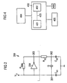
- FIG. 2 shows an oscillator Q which is connected to a first connection 201 on the one hand to a supply voltage V 0 and on the other hand to a first capacitance C X1 .
- the first capacitance C X1 is also connected to ground and to a second capacitance C X2 .
- the second capacitance C X2 is connected to the oscillator Q and an electrical resistor R X2 via a second connection 202.
- the second resistor R X2 is connected via a third connection 203 to an output of an inverter 204 and a series resistor R bias , both of which in turn are connected to the supply voltage via the first connection 201.
- the oscillation range with the associated dimensions (instances) of the further components is to be determined for the oscillator circuit 200.
- an instance i.e. a Dimensioning or defining the other components as well as the general conditions (operating conditions tolerances of the components).
- the method is shown on the basis of a predefined electrical resistance R X2 and predefined boundary conditions, that is to say the first capacitance C X1 and the second capacitance C X2 are each varied in a predeterminable dimensioning interval, each in a column in FIG 1 shown table for the second capacitance C X2 in picofarads (pF) and in a first row for the first capacitance C X1 in pF.
- a stability analysis of the oscillator circuit 200 is carried out for each instance.
- a Hopf bifurcation point 301 is a point of an electrical circuit at which the electrical Switching from a stable to an unstable, i.e. vibrating state passes.
- the Hopf bifurcation point 301 is determined in accordance with one of the methods described in [2], [3], or [4].
- the Hopf bifurcation point HP is described by a triple which has an eigenvalue ⁇ 0 , the imaginary part of which is also referred to as the natural frequency of the circuit, a rest position y 0 of the Hopf bifurcation point HP and an eigenvector v 0 .
- ⁇ 0 denotes the system parameter ⁇ for which the Hopf bifurcation point HP is obtained for the circuit.
- bifurcation planes ⁇ ⁇ are determined in a further step.
- the eigenvalue ⁇ ( ⁇ ) and the eigenvector v ( ⁇ ) are determined for the system parameter ⁇ and the corresponding solution y ( ⁇ ) in an environment of the Hopf bifurcation point HP with the corresponding system parameter ⁇ 0 .
- the Hopf bifurcation point HP results for the special system parameter ⁇ 0 .
- One way of forming the bifurcation planes ⁇ ⁇ is to use the eigenvectors v ( ⁇ ) to move in complex space C through the real parts Re ⁇ v ( ⁇ ) ⁇ or the imaginary parts Im ⁇ v (X) ⁇ of the eigenvectors v ( ⁇ ) to span the bifurcation planes ⁇ ⁇ .
- z cv ( ⁇ ), c ⁇ C ⁇
- the bifurcation plane family ⁇ results from the following rule:
- a factor c is any complex number.
- the bifurcation plane ⁇ ⁇ is two-dimensional
- the bifurcation plane ⁇ ⁇ is one-dimensional.
- the bifurcation level ⁇ ⁇ By using the bifurcation level ⁇ ⁇ and thus a transformation of the entire possible state space, in a complex technical system, which is described by a higher number of differential algebraic equations, from a very high-dimensional state space to determine the periodic state description to a low-dimensional space of one level, the bifurcation level ⁇ ⁇ , the determination of the periodic state description is possible.
- x (t) c p v ( ⁇ ) e i ⁇ ( ⁇ ) t + c p v ( ⁇ ) e -i ⁇ ( ⁇ ) t + y ( ⁇ )
- the factor cp is chosen such that c p v ( ⁇ ) gives the point P.
- T is the time at which the technical system is described is called.
- x can be seen as a flow velocity of a mechanical dynamic system to be viewed as.
- An energy function E (t) can be determined from the power function P (t) by integrating the power function P (t) over a period of the respective oscillation:
- This property can furthermore used to determine a point with which it is possible is a good periodic description of the condition Circuit estimate.
- the point is determined by moving along the curve in freely definable interval steps, the energy function E ( ⁇ ) is determined for a point on the curve. Since shown can be that a zero of the real part of the Energy function Re ⁇ E ( ⁇ ) ⁇ on the respective evaluated Point on the curve gives a very good point with which a very good periodic description of the condition of the circuit can be determined, a zero of the real part of the Energy function Re ⁇ E ( ⁇ ) ⁇ of the technical system determined.
- Zero analysis also called a derivative-free zero procedure be referred to.
- the curve be a semi-open, circular Curve around the Hopf bifurcation point.
- the periodic state description x (t) of the circuit is the periodic solution of the circuit for the system parameter ⁇ .
- the periodic description of the condition is used as a starting solution for the determination of further periodic solutions based on the starting solution, i.e. the periodic description of the condition, used.
- ⁇ can, for example, be the method of harmonic balance can be used.
- a second binary value 101 is inserted into the matrix 100 in the field that is clearly determined by the dimensions of the capacitances C X1 , C X2 .
- a first binary value 102 is assigned to the corresponding field in the matrix 100.
- a method for determining the transient response of a Quartz oscillator is carried out according to the method described in [3] is.
- This procedure corresponds to a scan of the edge area, making a review of a large sub-area throughout Matrix 100 is not required.
- the dimensionality of the matrix is 100 any.
- the other components are also corresponding basically arbitrary and, as described above, can be very different Parameters taken into account in the circuit simulation become.
- the computer 400 has a memory 401, one Processor unit 402, which is connected via a bus 403 to the memory 401 is connected to.
- the memory 401 is a description the oscillator circuit 200 in a circuit description language, e.g. SPICE saved.
- the processor unit 402 is set up such that the method steps described above are feasible for circuit simulation.
- a screen 404 is also provided for displaying the Results as well as a keyboard 405 and a mouse 406 for input of information in the computer 400.
Landscapes
- Engineering & Computer Science (AREA)
- Computer Hardware Design (AREA)
- Physics & Mathematics (AREA)
- Theoretical Computer Science (AREA)
- Microelectronics & Electronic Packaging (AREA)
- Evolutionary Computation (AREA)
- Geometry (AREA)
- General Engineering & Computer Science (AREA)
- General Physics & Mathematics (AREA)
- Oscillators With Electromechanical Resonators (AREA)
- Management, Administration, Business Operations System, And Electronic Commerce (AREA)
Claims (10)
- Procédé pour déterminer de manière assistée par ordinateur une zone d'amorçage d'oscillations d'un circuit électrique qui comporte au moins un oscillateur et des composants supplémentaires qui sont reliés à l'oscillateur,
dans lequel on effectue, dans un procédé itératif, en faisant varier des paramètres de connexion des composants supplémentaires chaque fois pour une combinaison des paramètres de connexion, les étapes suivantes :on effectue pour la combinaison de paramètres associés une analyse de stabilité du circuit,on détermine pour la combinaison de paramètres du circuit que la combinaison de paramètres amorce des oscillations, on associe ainsi dans une matrice dans laquelle sont mémorisées toutes les combinaisons de paramètres examinées une première valeur à la combinaison de paramètres, la première valeur indiquant que la combinaison de paramètres amorce des oscillations,on détermine pour la combinaison de paramètres du circuit que la combinaison de paramètres n'amorce pas d'oscillation, on associe ainsi dans la matrice une deuxième valeur à la combinaison de paramètres, la deuxième valeur indiquant que la combinaison de paramètres n'amorce pas d'oscillation,dans lequel on obtient la zone d'amorçage d'oscillations à partir des combinaisons de paramètres auxquelles la première valeur a été associée dans la matrice. - Procédé suivant la revendication 1,
dans lequel on effectue l'analyse de stabilité suivant l'un des procédés suivants :détermination d'un point de bifurcation Hopf pour l'instance associée,analyse de zéro polaire,analyse AC (analyse de petit signal) en utilisant le critère de Bode ou le critère de Nyquist,analyse de transitoires. - Procédé suivant la revendication 1 ou 2,
dans lequel les paramètres de connexion des composants supplémentaires comportent au moins l'un des paramètres suivants :températures différentes auxquelles le circuit est soumis,qualités différentes des composants supplémentaires,valeurs de dimensionnement différentes des composants supplémentaires. - Procédé suivant l'une des revendications 1 à 3, dans lequel on effectue une analyse de stabilité au point de fonctionnement au moins pour une partie des combinaisons de paramètres.
- Procédé suivant la revendication 4, dans lequel on effectue une détermination du régime transitoire de la combinaison de paramètres au moins pour une partie des combinaisons de paramètres.
- Dispositif pour déterminer de manière assistée. par ordinateur une zone d'amorçage d'oscillations d'un circuit électrique qui comporte au moins un oscillateur et des composants supplémentaires qui sont reliés à l'oscillateur,
comportant une unité de processeur qui est constituée de telle manière qu'il est effectué, dans un procédé itératif, en faisant varier des paramètres de connexion des composants supplémentaires chaque fois pour une combinaison des paramètres de connexion, les étapes suivantes :il est effectué une analyse de stabilité du circuit pour la combinaison de paramètres associés,s'il est déterminé pour la combinaison de paramètres de circuit que la combinaison de paramètres amorce des oscillations, il est associé dans une matrice dans laquelle sont mémorisées toutes les combinaisons de paramètres examinées une première valeur à la combinaison de paramètres, la première valeur indiquant que la combinaison de paramètres amorce des oscillations,s'il est déterminé pour la combinaison de paramètres du circuit que la combinaison de paramètres n'amorce pas d'oscillation, il est associé dans la matrice une deuxième valeur à la combinaison de paramètres, la deuxième valeur indiquant que la combinaison de paramètres n'amorce pas d'oscillation,la zone d'amorçage d'oscillations est obtenue à partir des combinaisons de paramètres auxquelles la première valeur a été associée dans la matrice. - Dispositif suivant la revendication 6,
dans lequel l'unité de processeur est constituée de telle manière que l'analyse de stabilité est effectuée suivant l'un des procédés suivants :détermination d'un point de bifurcation Hopf pour l'instance associée,analyse de zéro polaire,analyse AC (analyse de petit signal) en utilisant le critère de Bode ou le critère de Nyquist,analyse de transitoires. - Dispositif suivant la revendication 6 ou 7,
dans lequel l'unité de processeur est constituée de telle manière que les paramètres de connexion des composants supplémentaires comportent au moins l'un des paramètres suivants:températures différentes auxquelles le circuit est soumis,qualités différentes des composants supplémentaires,valeurs de dimensionnement différentes des composants supplémentaires. - Dispositif suivant l'une des revendications 6 à 8, dans lequel l'unité de processeur est constituée de telle manière qu'il est effectué une analyse de stabilisation au point de fonctionnement au moins pour une partie des combinaisons de paramètres.
- Dispositif suivant la revendication 9, dans lequel l'unité de processeur est constituée de telle manière qu'il est effectué une détermination du régime transitoire de la combinaison de paramètres au moins pour une partie des combinaisons de paramètres.
Applications Claiming Priority (3)
| Application Number | Priority Date | Filing Date | Title |
|---|---|---|---|
| DE19752606 | 1997-11-27 | ||
| DE19752606 | 1997-11-27 | ||
| PCT/EP1998/005600 WO1999028839A1 (fr) | 1997-11-27 | 1998-09-03 | Procede et dispositif de calcul assiste par ordinateur d'une zone d'amorce d'oscillation d'un circuit electrique |
Publications (2)
| Publication Number | Publication Date |
|---|---|
| EP1034494A1 EP1034494A1 (fr) | 2000-09-13 |
| EP1034494B1 true EP1034494B1 (fr) | 2001-11-28 |
Family
ID=7850000
Family Applications (1)
| Application Number | Title | Priority Date | Filing Date |
|---|---|---|---|
| EP98951347A Expired - Lifetime EP1034494B1 (fr) | 1997-11-27 | 1998-09-03 | Procede et dispositif de calcul assiste par ordinateur d'une zone d'amorce d'oscillation d'un circuit electrique |
Country Status (4)
| Country | Link |
|---|---|
| US (1) | US6320471B1 (fr) |
| EP (1) | EP1034494B1 (fr) |
| DE (1) | DE59802274D1 (fr) |
| WO (1) | WO1999028839A1 (fr) |
Families Citing this family (2)
| Publication number | Priority date | Publication date | Assignee | Title |
|---|---|---|---|---|
| HK1047430B (zh) | 1998-12-18 | 2005-06-10 | 大正制药株式会社 | 中间体及使用该中间体的含氟氨基酸化合物的制造方法 |
| CN112307698B (zh) * | 2019-07-29 | 2023-10-31 | 星宸科技股份有限公司 | 可控制振荡器的自动化设计的方法、电脑程式产品及系统 |
Family Cites Families (3)
| Publication number | Priority date | Publication date | Assignee | Title |
|---|---|---|---|---|
| US5444641A (en) * | 1993-09-24 | 1995-08-22 | Rockwell International Corporation | Admittance-parameter estimator for a piezoelectric resonator in an oscillator circuit |
| DE4411765A1 (de) | 1994-04-06 | 1995-10-12 | Werner Dipl Ing Anzill | Verfahren zum Entwurf von Oszillatoren mit minimiertem Rauschen |
| DE19602125C2 (de) * | 1996-01-22 | 1998-03-12 | Siemens Ag | Schaltungssimulationsverfahren zur rechnergestützten Bestimmung des Einschwingverhaltens einer Quarzresonatorschaltung |
-
1998
- 1998-07-09 US US09/555,204 patent/US6320471B1/en not_active Expired - Fee Related
- 1998-09-03 EP EP98951347A patent/EP1034494B1/fr not_active Expired - Lifetime
- 1998-09-03 DE DE59802274T patent/DE59802274D1/de not_active Expired - Fee Related
- 1998-09-03 WO PCT/EP1998/005600 patent/WO1999028839A1/fr not_active Ceased
Also Published As
| Publication number | Publication date |
|---|---|
| EP1034494A1 (fr) | 2000-09-13 |
| US6320471B1 (en) | 2001-11-20 |
| WO1999028839A1 (fr) | 1999-06-10 |
| DE59802274D1 (de) | 2002-01-10 |
Similar Documents
| Publication | Publication Date | Title |
|---|---|---|
| Vanassche et al. | Symbolic modeling of periodically time-varying systems using harmonic transfer matrices | |
| DE69616416T2 (de) | Verfahren zur Simulation einer Schaltung | |
| EP0855662A1 (fr) | Analyse électrique des circuits integrés | |
| DE69225527T2 (de) | Verfahren und System zur automatischen Bestimmung der logischen Funktion einer Schaltung | |
| DE102007016522A1 (de) | Quarzoszillator-Schaltkreis | |
| EP3881216A1 (fr) | Procédé mis en oeuvre par ordinateur pour la simulation d'un circuit électrique | |
| Antonov et al. | On regulation accuracy of current and voltage discrete values in testing facilities of semiconductor devices | |
| EP1062604B1 (fr) | Procede et dispositif pour determiner une defaillance d'un systeme technique | |
| EP1034494B1 (fr) | Procede et dispositif de calcul assiste par ordinateur d'une zone d'amorce d'oscillation d'un circuit electrique | |
| EP0909421B1 (fr) | Procede de determination assistee par ordinateur d'une fonction de convergence d'un systeme | |
| DE3887009T2 (de) | Elektronisches Netzwerk zur Nachbildung von Blindwiderständen. | |
| DE69919941T2 (de) | Modellierungsverfahren und Simulationsverfahren | |
| Verhaegen et al. | Efficient DDD-based symbolic analysis of linear analog circuits | |
| DE19602125C2 (de) | Schaltungssimulationsverfahren zur rechnergestützten Bestimmung des Einschwingverhaltens einer Quarzresonatorschaltung | |
| DE102004021421A1 (de) | Verfahren zur Bereitstellung eines Hochfrequenz-Ersatzschaltbilds für elektronische Bauteile | |
| EP1257904B1 (fr) | Procede pour produire une sequence de nombres aleatoires d'un bruit en 1/f | |
| Alvarez et al. | Semiclassical analysis of a quasi-exactly solvable system: second harmonic generation | |
| DE102023201340A1 (de) | Verfahren zur Simulierung einer leistungselektronischen Schaltzelle | |
| DE69709437T2 (de) | Invertierende Verstärkerschaltung | |
| EP0938716B1 (fr) | Procede assiste par ordinateur pour le partitionnement d'un circuit electrique | |
| DE69317528T2 (de) | Integrierte Schaltung mit einem elektrisch einstellbaren Parameter | |
| WO2021185762A1 (fr) | Procédé et dispositif pour déterminer la sensibilité d'une valeur caractéristique d'un circuit électronique | |
| DE10205916A1 (de) | Verfahren zur Bestimmung von Hopf-Bifurkationspunkten einer periodischen Zustandsbeschreibung eines technischen Systems | |
| DE202025106364U1 (de) | Ein Spannungsdifferenz-Stromübertragungs-Transkonduktanzverstärkersystem | |
| DE60103154T2 (de) | Automatisches gerät für testbarkeitsanalyse |
Legal Events
| Date | Code | Title | Description |
|---|---|---|---|
| PUAI | Public reference made under article 153(3) epc to a published international application that has entered the european phase |
Free format text: ORIGINAL CODE: 0009012 |
|
| 17P | Request for examination filed |
Effective date: 20000510 |
|
| AK | Designated contracting states |
Kind code of ref document: A1 Designated state(s): DE FR GB |
|
| GRAG | Despatch of communication of intention to grant |
Free format text: ORIGINAL CODE: EPIDOS AGRA |
|
| GRAG | Despatch of communication of intention to grant |
Free format text: ORIGINAL CODE: EPIDOS AGRA |
|
| GRAH | Despatch of communication of intention to grant a patent |
Free format text: ORIGINAL CODE: EPIDOS IGRA |
|
| 17Q | First examination report despatched |
Effective date: 20001204 |
|
| GRAH | Despatch of communication of intention to grant a patent |
Free format text: ORIGINAL CODE: EPIDOS IGRA |
|
| GRAA | (expected) grant |
Free format text: ORIGINAL CODE: 0009210 |
|
| AK | Designated contracting states |
Kind code of ref document: B1 Designated state(s): DE FR GB |
|
| REG | Reference to a national code |
Ref country code: GB Ref legal event code: IF02 |
|
| REF | Corresponds to: |
Ref document number: 59802274 Country of ref document: DE Date of ref document: 20020110 |
|
| GBT | Gb: translation of ep patent filed (gb section 77(6)(a)/1977) |
Effective date: 20020207 |
|
| ET | Fr: translation filed | ||
| PLBE | No opposition filed within time limit |
Free format text: ORIGINAL CODE: 0009261 |
|
| STAA | Information on the status of an ep patent application or granted ep patent |
Free format text: STATUS: NO OPPOSITION FILED WITHIN TIME LIMIT |
|
| 26N | No opposition filed | ||
| PGFP | Annual fee paid to national office [announced via postgrant information from national office to epo] |
Ref country code: GB Payment date: 20060921 Year of fee payment: 9 |
|
| PGFP | Annual fee paid to national office [announced via postgrant information from national office to epo] |
Ref country code: FR Payment date: 20060922 Year of fee payment: 9 |
|
| PGFP | Annual fee paid to national office [announced via postgrant information from national office to epo] |
Ref country code: DE Payment date: 20061114 Year of fee payment: 9 |
|
| GBPC | Gb: european patent ceased through non-payment of renewal fee |
Effective date: 20070903 |
|
| PG25 | Lapsed in a contracting state [announced via postgrant information from national office to epo] |
Ref country code: DE Free format text: LAPSE BECAUSE OF NON-PAYMENT OF DUE FEES Effective date: 20080401 |
|
| REG | Reference to a national code |
Ref country code: FR Ref legal event code: ST Effective date: 20080531 |
|
| PG25 | Lapsed in a contracting state [announced via postgrant information from national office to epo] |
Ref country code: FR Free format text: LAPSE BECAUSE OF NON-PAYMENT OF DUE FEES Effective date: 20071001 |
|
| PG25 | Lapsed in a contracting state [announced via postgrant information from national office to epo] |
Ref country code: GB Free format text: LAPSE BECAUSE OF NON-PAYMENT OF DUE FEES Effective date: 20070903 |