EP1034765A2 - Dispositif pour faciliter l'entrée et la sortie d'un véhicule des transports publics en particulier un véhicule approchant un perron - Google Patents
Dispositif pour faciliter l'entrée et la sortie d'un véhicule des transports publics en particulier un véhicule approchant un perron Download PDFInfo
- Publication number
- EP1034765A2 EP1034765A2 EP00102673A EP00102673A EP1034765A2 EP 1034765 A2 EP1034765 A2 EP 1034765A2 EP 00102673 A EP00102673 A EP 00102673A EP 00102673 A EP00102673 A EP 00102673A EP 1034765 A2 EP1034765 A2 EP 1034765A2
- Authority
- EP
- European Patent Office
- Prior art keywords
- cassette
- vehicle
- ramp
- section
- pivotable
- Prior art date
- Legal status (The legal status is an assumption and is not a legal conclusion. Google has not performed a legal analysis and makes no representation as to the accuracy of the status listed.)
- Withdrawn
Links
Images


Classifications
-
- B—PERFORMING OPERATIONS; TRANSPORTING
- B60—VEHICLES IN GENERAL
- B60R—VEHICLES, VEHICLE FITTINGS, OR VEHICLE PARTS, NOT OTHERWISE PROVIDED FOR
- B60R3/00—Arrangements of steps or ladders facilitating access to or on the vehicle, e.g. running-boards
- B60R3/02—Retractable steps or ladders, e.g. movable under shock
-
- A—HUMAN NECESSITIES
- A61—MEDICAL OR VETERINARY SCIENCE; HYGIENE
- A61G—TRANSPORT, PERSONAL CONVEYANCES, OR ACCOMMODATION SPECIALLY ADAPTED FOR PATIENTS OR DISABLED PERSONS; OPERATING TABLES OR CHAIRS; CHAIRS FOR DENTISTRY; FUNERAL DEVICES
- A61G3/00—Ambulance aspects of vehicles; Vehicles with special provisions for transporting patients or disabled persons, or their personal conveyances, e.g. for facilitating access of, or for loading, wheelchairs
- A61G3/02—Loading or unloading personal conveyances; Facilitating access of patients or disabled persons to, or exit from, vehicles
- A61G3/06—Transfer using ramps, lifts or the like
- A61G3/061—Transfer using ramps, lifts or the like using ramps
-
- A—HUMAN NECESSITIES
- A61—MEDICAL OR VETERINARY SCIENCE; HYGIENE
- A61G—TRANSPORT, PERSONAL CONVEYANCES, OR ACCOMMODATION SPECIALLY ADAPTED FOR PATIENTS OR DISABLED PERSONS; OPERATING TABLES OR CHAIRS; CHAIRS FOR DENTISTRY; FUNERAL DEVICES
- A61G3/00—Ambulance aspects of vehicles; Vehicles with special provisions for transporting patients or disabled persons, or their personal conveyances, e.g. for facilitating access of, or for loading, wheelchairs
- A61G3/02—Loading or unloading personal conveyances; Facilitating access of patients or disabled persons to, or exit from, vehicles
- A61G3/06—Transfer using ramps, lifts or the like
- A61G3/067—Transfer using ramps, lifts or the like with compartment for horizontally storing the ramp or lift
Definitions
- the invention relates to a device for relief of getting on and off a vehicle of the public transport, especially one Platforms approaching vehicle with the characteristics the preamble of claim 1.
- a device with the features from the preamble of claim 1 is in EP 0 416 539 A1 described.
- this known boarding device is the closed cassette in which the ramp is guided is, as a whole - together with the ramp - pivotable about a horizontal axis of rotation.
- the known devices are partly constructive relatively expensive, own large, of wheelchair users and angles that are difficult to overcome difficult to adapt to different platform heights, especially if the platform edge is higher than the vehicle floor.
- the invention has for its object a device to facilitate getting on and off on a vehicle for public transport, in particular a vehicle approaching a platform, with the features from the preamble of the claim 1 so that it is structurally simple is built, is easy to install and remove and adapted to existing conditions of the vehicle floor can be. It should also go out protrude only a little into the traffic area and still with a relatively small angle of inclination Get along ramp. It should be expandable so that even platforms that can be reached are the same are high or slightly higher than the vehicle floor.
- a basic idea of the invention is that as closed cassette trained device that in this version also in existing vehicles can be easily retrofitted so that that the entire cassette is not horizontal Axis of rotation is pivoted, but on the one hand a section of the upper part of the cassette or also the entire upper part of the cassette forming the vehicle floor around a first one running in the longitudinal direction of the vehicle horizontal axis of rotation is pivotable and also the ramp itself regardless of the pivoting the cassette when extending or after Extend a second, in the vehicle's longitudinal direction extending horizontal axis of rotation is pivotable. Both swivel movements are said to be specific Training of the cassette so that the outward-facing edges of the upper part of the cassette and / or the ramp can be raised or lowered can.
- the structure of the device according to the invention is very flexible and can adapt to extremely different Installation conditions and functional conditions be adjusted.
- the in the vehicle in the boarding area built-in, transverse to the vehicle from the leading edge to immediately before Cartridge extending the vehicle side member can thus be formed that the axis of rotation of the pivotable Section of the upper part of the cassette on which the Arranged vehicle center facing end of the cassette , whereby the upper part of the cassette is achieved along its entire length as an extension of the Ramp is available.
- the front, facing the manhole Part that is, for example, half the cassette length can correspond to swivel design.
- the pivoting movement of the pivotable section the upper part of the cassette can be moved in and out the ramp can be effected, but it can also a separate one for generating this swivel movement Drive device be present.
- Trap becomes the flexibility of the applicability of the invention Device enhanced by it is possible, for example, the pivotable section of the upper part of the cassette in a basic position to leave in the vehicle floor at this Point is slightly lowered to the outside. From this He can then set the home position for special purposes a horizontal position raised and locked there become. This can be extraordinary, for example be beneficial if in the boarding area while driving a wheelchair should be placed, for example on a device the invention provided entry door that at least turned away from the platform for a number of stations is.
- the movement of the ramp can be done by means of a curve be adapted to the existing conditions such that in particular in the last section of the Extend the necessary lifting and lowering movements stamped on the ramp.
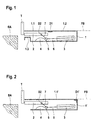
- Fig. 1 lies the edge of platform BA slightly below the height of the vehicle floor FB.
- the entry area is below a cassette 1 is arranged on the vehicle floor, the top of the cassette consisting of two sections 1.1 and 1.2 exist, both in this area form part of the vehicle floor.
- the outer Section 1.1 is up and about an axis of rotation D1 swiveling downward while the inner section 1.2 is firmly arranged and constantly in alignment to the vehicle floor FB.
- an extendable ramp 2 is arranged, the extension and retraction from a drive device 3 is effected from, for simplicity in shown in this example as a pneumatic cylinder is.
- any other suitable drive device used for such purposes be, for example a spindle drive or a toothed belt drive.
- the drive device 3 is via only symbolically shown guide and connection devices 6 and 7 connected to ramp 2, whereby the movement sequence of the ramp through a roller 5 running on a curve guide 4 is set.
- the first axis of rotation lies D1 for the outer section 1.1 of the upper part of the cassette about in the middle of the cassette 1 and the basic position this section runs horizontally.
- ramp 2 drives, driven by the device 3, ramp 2 towards the platform BA, whereby, controlled by the curve guide 4, first lifts up and then extends to the Platform BA lowered.
- the lowering movement of the outer Section 1.1 is also controlled by ramp 2, so that the outer section 1.1 of the lifting and Lowering of ramp 2 follows and not shown extended state of the ramp 2 over the ramp 2 and the outer, now from the Basic position of the section lowered to the outside 1.1 of the cassette top leading entry path to still horizontal inner section 1.2 and thus leads to the vehicle floor FB.
- the door T can also be opened without that ramp 2 extends. In this case, too the outer section 1.1 of the upper part of the cassette in the horizontal home position.
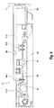
- FIG. 2 shows in an analogous representation as in FIG. 1, a slightly different embodiment of the device, in which the entire upper part 1.1 'of the cassette 1' around one on the rear edge of the cassette Axis of rotation D1 'can be pivoted downwards.
- the remaining Parts are shown in the same way and provided with reference numerals, as in Fig. 1.
- These Embodiment is particularly suitable if the Upper edge of platform BA by a considerable amount Is a bit lower than the vehicle floor FB and certain The angle of inclination on the entry path must not be exceeded should be.
- the pivoting movement of the upper cassette part 1.1 'can can be controlled either by the extending ramp 2 or it can have its own drive device be provided.
- the device shown in Fig. 3 is in its Basic principle as well as the device 2 by the entire upper part 1.1 '' of Cassette 1 '' around one on the rear edge of the cassette arranged axis of rotation D1 '' are pivoted can.
- This embodiment is for use on Platforms BA 'thought where the platform edge at the same height as the vehicle floor FB or even is a little higher.
- the cassette top 1.1 '' a basic position, compared to the horizontal, around the axis of rotation D1 '' is lowered.
- Platform 2 also has one correspondingly lowered basic position about the axis of rotation D2 ''.
- FIG. 4 Another possibility of this embodiment is shown in Fig. 4.
- the axis of rotation D1 '' ' for the cassette top 1.1' '' on the inside, the End of the cassette 1 '' 'facing the center of the vehicle, so that the entire cassette top 1.1 ''' ' can be lowered and raised.
- the Ramp 2 runs, driven by the drive device 3 and lifts, controlled by the curve 4 '' 'pivoting about the second axis of rotation D2' '', something on.
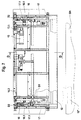
- FIG. 5 and 6 show in a highly schematic Representation of a local public transport vehicle in the form of a NFB bus connected to its a device for each of the two entrance doors to facilitate boarding and alighting, which are denoted overall by R1 and R2.
- Both Devices R1 and R2 extend from the leading edge towards the center of the vehicle until immediately in front of the longitudinal beam LT, which is due to the installation of the devices in no way impaired become.
- FIGS. 5 and 6 show one of the two devices R1 and R2 from FIGS. 5 and 6 in one embodiment, which is given in principle by Fig. 1.
- the device is as in the boarding area of the vehicle arranged and integrated in the vehicle floor FB Cassette 11 formed, a front Section 11.1 of the upper part of the cassette Axis of rotation D1 is pivotable in such a way that after outside edge can be lowered.
- the one in the middle of the vehicle lying section 11.2 of the upper part of the cassette is, however, firmly arranged and runs horizontal and aligned with the vehicle floor FB.
- the drive device for the extendable Ramp 12 is an electric motor 13 that has a drive belt 13.1 and one at the back of the cassette 11 arranged shaft 16.2 arranged on both sides Drives timing belt 16 with which the ramp 12th is connected via connecting devices 16.1.
- the ramp 12 is based on support wheels 15 on curve guides 14, which means that they are against At the end of the extension movement, a lowering movement of the front Partly executes.
- This lowering movement follows outer section 11.1 of the upper part of the cassette 11.
- the cassette 11 is through a protective flap 18 closed upwards can be swiveled up and down when the ramp is extended 12 hangs up on the top of the ramp and one Transition between ramp 12 and the swiveling outer section 11.1 of the upper part of the cassette represents.
- Fig. 8 the ramp 12 is in solid lines in shown in the retracted position while dashed Positions 12 'and 12' 'an intermediate position or the position on platform BA represent.
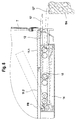
- FIG. 10 shows a variant of the device according to FIG. 7 to 9 in one embodiment, the principle is given by Fig. 2.
- This device is also considered in the vehicle floor FB integrated cassette 21, being different to the device according to FIGS. 7 to 9 here pivotable section 21.1 of the upper part of the cassette up to the end facing the center of the vehicle the cassette 21 extends and there about the axis of rotation D 1 ' is pivotable. In its rest position, the pivoting section 21.1 horizontally and in alignment to the vehicle floor FB.
- the extendable ramp 22 is inside the cassette 21 arranged, the side guides in Fig. 10 not are visible.
- the drive device for the extendable Ramp 22 is in turn an electric motor 23, the one via a drive belt 23.1 and one at the rear End of the cassette 21 arranged shaft 26.2
- Timing belt 26 drives with which the ramp 22 over Connection devices 26.1 is connected.
- the ramp 22 is supported on a support wheels 25 Curve guide 24 from.
- the curve guide 24 has a portion 24.1 of its door end first up and then down. this has with the result that the front part of the ramp 22 against At the end of the extension movement, first a lifting movement and then makes a lowering motion.
- This movement section 21.1 of the upper part of the cassette also follows.
- the cassette is also on its front edge 21 closed by a protective flap 28, according to is swiveled up and when extending the Ramp 22 is placed on top of the ramp.
Landscapes
- Health & Medical Sciences (AREA)
- Public Health (AREA)
- Life Sciences & Earth Sciences (AREA)
- Animal Behavior & Ethology (AREA)
- General Health & Medical Sciences (AREA)
- Veterinary Medicine (AREA)
- Engineering & Computer Science (AREA)
- Mechanical Engineering (AREA)
- Vehicle Step Arrangements And Article Storage (AREA)
Applications Claiming Priority (2)
| Application Number | Priority Date | Filing Date | Title |
|---|---|---|---|
| DE19909700A DE19909700A1 (de) | 1999-03-05 | 1999-03-05 | Vorrichtung zur Erleichterung des Ein- und Aussteigens an einem Fahrzeug des öffentlichen Personenverkehrs, insbesondere einem Bahnsteige anfahrenden Fahrzeug |
| DE19909700 | 1999-03-05 |
Publications (2)
| Publication Number | Publication Date |
|---|---|
| EP1034765A2 true EP1034765A2 (fr) | 2000-09-13 |
| EP1034765A3 EP1034765A3 (fr) | 2001-05-16 |
Family
ID=7899814
Family Applications (1)
| Application Number | Title | Priority Date | Filing Date |
|---|---|---|---|
| EP00102673A Withdrawn EP1034765A3 (fr) | 1999-03-05 | 2000-02-09 | Dispositif pour faciliter l'entrée et la sortie d'un véhicule des transports publics en particulier un véhicule approchant un perron |
Country Status (2)
| Country | Link |
|---|---|
| EP (1) | EP1034765A3 (fr) |
| DE (1) | DE19909700A1 (fr) |
Cited By (5)
| Publication number | Priority date | Publication date | Assignee | Title |
|---|---|---|---|---|
| EP1386818A1 (fr) * | 2002-07-31 | 2004-02-04 | Pintsch Bamag Antriebs- und Verkehrstechnik GmbH | Marchepied déployable, en particulier pour véhicules ferroviaires |
| WO2005030551A1 (fr) * | 2003-09-18 | 2005-04-07 | Knorr-Bremse Ges. M.B.H. | Marche coulissante |
| EP2401994A2 (fr) | 2010-07-02 | 2012-01-04 | ALSTOM Transport SA | Agencement d'accès entre un véhicule et un quai |
| WO2015063432A1 (fr) * | 2013-11-04 | 2015-05-07 | Myd"L" | Dispositif d'assistance pour personne a mobilité réduite |
| EP3798084A1 (fr) * | 2019-09-30 | 2021-03-31 | Faiveley Transport Tours | Ensemble de marchepied pour vehicule de transport, vehicule ainsi equipe et procede de mise en oeuvre de ce vehicule |
Families Citing this family (4)
| Publication number | Priority date | Publication date | Assignee | Title |
|---|---|---|---|---|
| DE202005011221U1 (de) | 2005-07-16 | 2006-12-07 | Gebr. Bode Gmbh & Co. Kg | Ausfahrbare Einstiegsrampe für Fahrzeuge des öffentlichen Personenverkehrs |
| DE102017206495A1 (de) | 2017-04-18 | 2018-10-18 | Siemens Aktiengesellschaft | Vorrichtung und Verfahren zur Herstellung eines niveaugleichen Einstiegs für unterschiedliche Bahnsteighöhen |
| DE102024202973B3 (de) | 2024-03-28 | 2025-07-31 | Siemens Mobility GmbH | Verfahren und Vorrichtung zur Erzeugung eines digitalen Abbilds einer Trasse eines Schienenfahrzeugs |
| DE102024202974A1 (de) | 2024-03-28 | 2025-10-02 | Siemens Mobility GmbH | Verfahren und spurgeführtes Fahrzeug zur Positionsbestimmung des spurgeführten Fahrzeugs |
Citations (2)
| Publication number | Priority date | Publication date | Assignee | Title |
|---|---|---|---|---|
| EP0217265A1 (fr) | 1985-09-25 | 1987-04-08 | Gec Alsthom Sa | Dispositif permettant un acces aisé aux véhicules ferroviaires lors des arrêts en station |
| EP0416539A1 (fr) | 1989-09-08 | 1991-03-13 | Karl Kässbohrer Fahrzeugwerke GmbH | Dispositif d'accès pour véhicules automobiles, en particulier pour autobus |
Family Cites Families (3)
| Publication number | Priority date | Publication date | Assignee | Title |
|---|---|---|---|---|
| US4662021A (en) * | 1984-06-25 | 1987-05-05 | Hagen James P | Dockboard with a tread plate lock mechanism |
| US5636399A (en) * | 1995-02-27 | 1997-06-10 | Ricon Corporation | Movable ramp assembly |
| US5676515A (en) * | 1996-06-03 | 1997-10-14 | Haustein; Norman E. | Low floor vehicle ramp |
-
1999
- 1999-03-05 DE DE19909700A patent/DE19909700A1/de not_active Withdrawn
-
2000
- 2000-02-09 EP EP00102673A patent/EP1034765A3/fr not_active Withdrawn
Patent Citations (2)
| Publication number | Priority date | Publication date | Assignee | Title |
|---|---|---|---|---|
| EP0217265A1 (fr) | 1985-09-25 | 1987-04-08 | Gec Alsthom Sa | Dispositif permettant un acces aisé aux véhicules ferroviaires lors des arrêts en station |
| EP0416539A1 (fr) | 1989-09-08 | 1991-03-13 | Karl Kässbohrer Fahrzeugwerke GmbH | Dispositif d'accès pour véhicules automobiles, en particulier pour autobus |
Cited By (10)
| Publication number | Priority date | Publication date | Assignee | Title |
|---|---|---|---|---|
| EP1386818A1 (fr) * | 2002-07-31 | 2004-02-04 | Pintsch Bamag Antriebs- und Verkehrstechnik GmbH | Marchepied déployable, en particulier pour véhicules ferroviaires |
| WO2005030551A1 (fr) * | 2003-09-18 | 2005-04-07 | Knorr-Bremse Ges. M.B.H. | Marche coulissante |
| CN100434318C (zh) * | 2003-09-18 | 2008-11-19 | 克诺尔-布里姆斯股份有限公司 | 滑动踏板 |
| US7793596B2 (en) | 2003-09-18 | 2010-09-14 | Knorr-Bremse Ges. M. B. H. | Retractable step |
| EP2401994A2 (fr) | 2010-07-02 | 2012-01-04 | ALSTOM Transport SA | Agencement d'accès entre un véhicule et un quai |
| WO2015063432A1 (fr) * | 2013-11-04 | 2015-05-07 | Myd"L" | Dispositif d'assistance pour personne a mobilité réduite |
| FR3012832A1 (fr) * | 2013-11-04 | 2015-05-08 | Myd L | Dispositif d'assistance pour personne a mobilite reduite |
| EP3798084A1 (fr) * | 2019-09-30 | 2021-03-31 | Faiveley Transport Tours | Ensemble de marchepied pour vehicule de transport, vehicule ainsi equipe et procede de mise en oeuvre de ce vehicule |
| FR3101314A1 (fr) * | 2019-09-30 | 2021-04-02 | Faiveley Transport Tours | Ensemble de marchepied pour véhicule de transport, véhicule ainsi équipé et procédé de mise en œuvre de ce véhicule |
| US11634080B2 (en) | 2019-09-30 | 2023-04-25 | Faiveley Transport Tours | Transport vehicle walkway assembly |
Also Published As
| Publication number | Publication date |
|---|---|
| EP1034765A3 (fr) | 2001-05-16 |
| DE19909700A1 (de) | 2000-09-07 |
Similar Documents
| Publication | Publication Date | Title |
|---|---|---|
| EP1663751B1 (fr) | Marche coulissante | |
| EP0381066B1 (fr) | Toit de véhicule ayant une découpure de toit fermant au moyen d'un couvercle | |
| EP0863817A1 (fr) | Toit de vehicule avec au moins un couvercle | |
| EP0416539B1 (fr) | Dispositif d'accès pour véhicules automobiles, en particulier pour autobus | |
| DE2620683B2 (de) | Einstieganordnung für ein Nahverkehrsfahrzeug, insbesondere Schienenfahrzeug | |
| DE2330944A1 (de) | Tueranordnung fuer einen eisenbahnpersonenwagen | |
| EP3900982A1 (fr) | Système d'entrée pourvu de rabat d'étanchéité accessible | |
| DE60309537T2 (de) | Aufbau für eine Schiebeseitentür für Fahrzeuge | |
| EP1034765A2 (fr) | Dispositif pour faciliter l'entrée et la sortie d'un véhicule des transports publics en particulier un véhicule approchant un perron | |
| DE19531284A1 (de) | Schienenfahrzeug für den Personenverkehr | |
| DE10392237B4 (de) | Rampenanordnung mit einem Hub- und Verriegelungsmechanismus | |
| DE4441929A1 (de) | Zustiegsvorrichtung für Fahrzeuge, insbesondere Schienenfahrzeuge oder Kraftfahrzeuge, insbesondere für Niederflur-Omnibusse | |
| EP3974281B1 (fr) | Dispositif de montée pour un véhicule | |
| DE8816941U1 (de) | Rollstuhl-Einstieg im Bereich des Fahrerplatzes von Fahrzeugen zur Personenbeförderung, insbesondere Linienbusse | |
| DE2301998A1 (de) | Flugzeugladebruecke | |
| DE102016125785B4 (de) | Türvorrichtung für ein Schienenfahrzeug | |
| EP4288318B1 (fr) | Système d'embarquement ayant un marchepied coulissant et un joint d'étanchéité actif | |
| EP0094607A2 (fr) | Elévateur incliné pour un fauteuil roulant ou similaire monté sur un véhicule | |
| DE3519299A1 (de) | Vorrichtung zur befoerderung eines behinderten-fahrstuhls | |
| EP3583011B1 (fr) | Dispositif et procédé de réalisation d'un accès à niveau pour différentes hauteurs de quais | |
| DE4412689C2 (de) | Rollstuhldachkoffer | |
| EP1595737A2 (fr) | Rampe extensible pour véhicules de transport en commun | |
| DE102023125043B4 (de) | System zum Öffnen einer Öffnung einer Tür | |
| DE3331125C2 (de) | Schiebedach für Fahrzeuge | |
| DE69300244T2 (de) | Hubladeeinrichtung zur Anwendung an einem Lastwagenbehälter. |
Legal Events
| Date | Code | Title | Description |
|---|---|---|---|
| PUAI | Public reference made under article 153(3) epc to a published international application that has entered the european phase |
Free format text: ORIGINAL CODE: 0009012 |
|
| AK | Designated contracting states |
Kind code of ref document: A2 Designated state(s): AT BE CH CY DE DK ES FI FR GB GR IE IT LI LU MC NL PT SE |
|
| AX | Request for extension of the european patent |
Free format text: AL;LT;LV;MK;RO;SI |
|
| PUAL | Search report despatched |
Free format text: ORIGINAL CODE: 0009013 |
|
| AK | Designated contracting states |
Kind code of ref document: A3 Designated state(s): AT BE CH CY DE DK ES FI FR GB GR IE IT LI LU MC NL PT SE |
|
| AX | Request for extension of the european patent |
Free format text: AL;LT;LV;MK;RO;SI |
|
| 17P | Request for examination filed |
Effective date: 20011115 |
|
| AKX | Designation fees paid |
Free format text: AT BE CH CY DE DK ES FI FR GB GR IE IT LI LU MC NL PT SE |
|
| 17Q | First examination report despatched |
Effective date: 20040723 |
|
| STAA | Information on the status of an ep patent application or granted ep patent |
Free format text: STATUS: THE APPLICATION IS DEEMED TO BE WITHDRAWN |
|
| 18D | Application deemed to be withdrawn |
Effective date: 20050203 |